2010 GMC SIERRA Section 7
[x] Cancel search: Section 7Page 204 of 630
When the System Does Not Seem To
Work Properly
The rear vision camera system might not work properly
or display a clear image if:
.The RVC is turned off. See“Turning the Rear
Camera System On or Off” earlier in this section.
.It is dark.
.The sun or the beam of headlights is shining
directly into the camera lens.
.Ice, snow, mud, or anything else builds up on the
camera lens. Clean the lens, rinse it with water,
and wipe it with a soft cloth.
.The back of the vehicle is in an accident, the
position and mounting angle of the camera can
change or the camera can be affected. Be sure to
have the camera and its position and mounting
angle checked at your dealer/retailer. The rear vision camera system display in the rearview
mirror may turn off or not appear as expected due to
one of the following conditions. If this occurs the left
indicator light on the mirror will flash.
.A slow flash may indicate a loss of video signal,
or no video signal present during the reverse cycle.
.A fast flash may indicate that the display has been
on for the maximum allowable time during a
reverse cycle, or the display has reached an Over
Temperature limit.
The fast flash conditions are used to protect the
video device from high temperature conditions.
Once conditions return to normal the device will
reset and the green indicator will stop flashing.
During any of these fault conditions, the display will be
blank and the indicator will continue to flash as long as
the vehicle is in R (Reverse) or until the conditions
return to normal.
Pressing and holding
zwhen the left indicator light is
flashing will turn off the video display along with the left
indicator light.
3-68
Page 205 of 630
Universal Home Remote
System
SeeRadio Frequency Statementon page 8‑19for
information regarding Part 15 of the Federal
Communications Commission (FCC) Rules and
RSS-210/211 of Industry and Science Canada.
Universal Home Remote System
Operation (With Three Round LED)
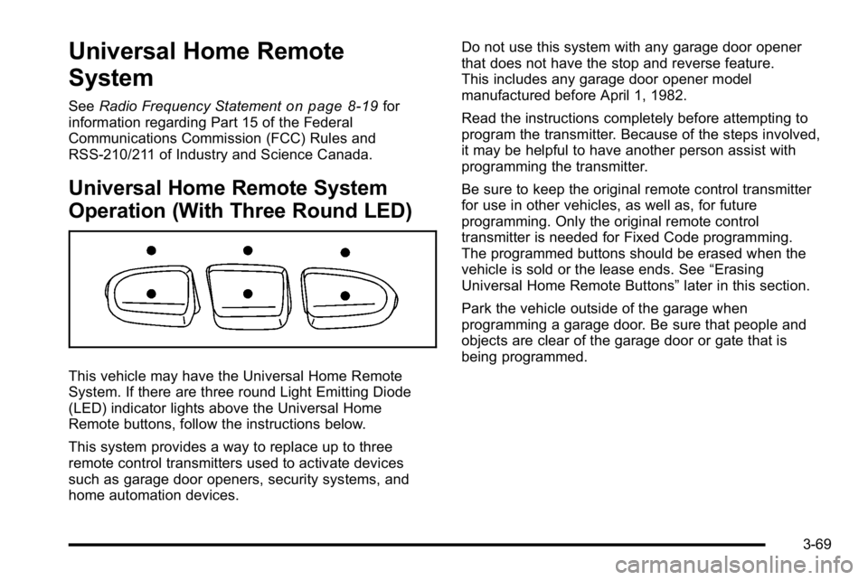
This vehicle may have the Universal Home Remote
System. If there are three round Light Emitting Diode
(LED) indicator lights above the Universal Home
Remote buttons, follow the instructions below.
This system provides a way to replace up to three
remote control transmitters used to activate devices
such as garage door openers, security systems, and
home automation devices. Do not use this system with any garage door opener
that does not have the stop and reverse feature.
This includes any garage door opener model
manufactured before April 1, 1982.
Read the instructions completely before attempting to
program the transmitter. Because of the steps involved,
it may be helpful to have another person assist with
programming the transmitter.
Be sure to keep the original remote control transmitter
for use in other vehicles, as well as, for future
programming. Only the original remote control
transmitter is needed for Fixed Code programming.
The programmed buttons should be erased when the
vehicle is sold or the lease ends. See
“Erasing
Universal Home Remote Buttons” later in this section.
Park the vehicle outside of the garage when
programming a garage door. Be sure that people and
objects are clear of the garage door or gate that is
being programmed.
3-69
Page 208 of 630
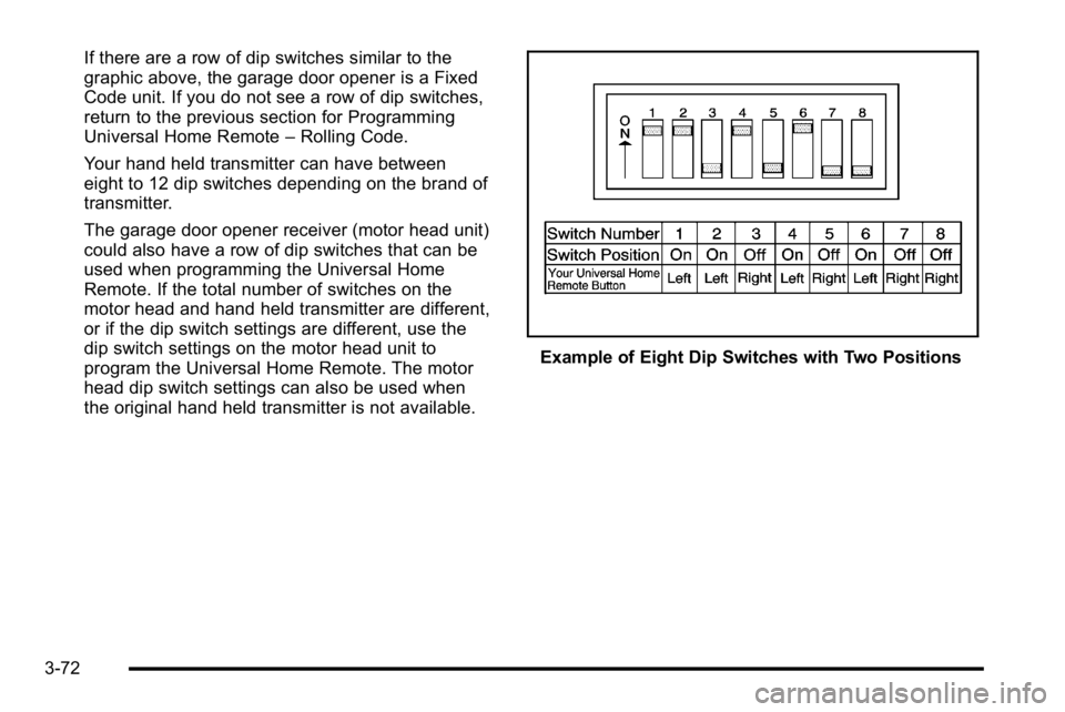
If there are a row of dip switches similar to the
graphic above, the garage door opener is a Fixed
Code unit. If you do not see a row of dip switches,
return to the previous section for Programming
Universal Home Remote–Rolling Code.
Your hand held transmitter can have between
eight to 12 dip switches depending on the brand of
transmitter.
The garage door opener receiver (motor head unit)
could also have a row of dip switches that can be
used when programming the Universal Home
Remote. If the total number of switches on the
motor head and hand held transmitter are different,
or if the dip switch settings are different, use the
dip switch settings on the motor head unit to
program the Universal Home Remote. The motor
head dip switch settings can also be used when
the original hand held transmitter is not available.
Example of Eight Dip Switches with Two Positions
3-72
Page 219 of 630
Section 4 Instrument Panel
Instrument Panel Overview. . . . . . . . . . . . . . . . . . . . . . . .4-3
Hazard Warning Flashers . . . . . . . . . . . . . . . . . . . . . . . 4-3
Horn . . . . . . . . . . . . . . . . . . . . . . . . . . . . . . . . . . . . . . . . . . . . 4-3
Tilt Wheel . . . . . . . . . . . . . . . . . . . . . . . . . . . . . . . . . . . . . . . 4-3
Turn Signal/Multifunction Lever . . . . . . . . . . . . . . . . . . 4-4
Turn and Lane-Change Signals . . . . . . . . . . . . . . . . . 4-4
Headlamp High/Low-Beam Changer . . . . . . . . . . . . 4-5
Flash-to-Pass . . . . . . . . . . . . . . . . . . . . . . . . . . . . . . . . . . . 4-5
Windshield Wipers . . . . . . . . . . . . . . . . . . . . . . . . . . . . . . 4-6
Windshield Washer . . . . . . . . . . . . . . . . . . . . . . . . . . . . . 4-6
Cruise Control . . . . . . . . . . . . . . . . . . . . . . . . . . . . . . . . . . 4-7
Exterior Lamps . . . . . . . . . . . . . . . . . . . . . . . . . . . . . . . . 4-10
Headlamps on Reminder . . . . . . . . . . . . . . . . . . . . . . . 4-11
Daytime Running Lamps (DRL) . . . . . . . . . . . . . . . . 4-12
Automatic Headlamp System . . . . . . . . . . . . . . . . . . 4-12
Puddle Lamps . . . . . . . . . . . . . . . . . . . . . . . . . . . . . . . . . 4-13
Fog Lamps . . . . . . . . . . . . . . . . . . . . . . . . . . . . . . . . . . . . 4-13
Auxiliary Roof-Mounted Lamp . . . . . . . . . . . . . . . . . 4-14
Instrument Panel Brightness . . . . . . . . . . . . . . . . . . . 4-14
Dome Lamps . . . . . . . . . . . . . . . . . . . . . . . . . . . . . . . . . . 4-14
Dome Lamp Override . . . . . . . . . . . . . . . . . . . . . . . . . . 4-15
Entry Lighting . . . . . . . . . . . . . . . . . . . . . . . . . . . . . . . . . . 4-15
Exit Lighting . . . . . . . . . . . . . . . . . . . . . . . . . . . . . . . . . . . 4-15
Reading Lamps . . . . . . . . . . . . . . . . . . . . . . . . . . . . . . . . 4-15
Cargo Lamp . . . . . . . . . . . . . . . . . . . . . . . . . . . . . . . . . . . 4-15 Electric Power Management . . . . . . . . . . . . . . . . . . . 4-16
Battery Run-Down Protection . . . . . . . . . . . . . . . . . . 4-16
Accessory Power Outlet(s) . . . . . . . . . . . . . . . . . . . . . 4-17
Ashtray(s) and Cigarette Lighter . . . . . . . . . . . . . . . 4-18
Climate Controls . . . . . . . . . . . . . . . . . . . . . . . . . . . . . . . . . . 4-18
Climate Control System (With Heater Only) . . . . 4-18
Climate Control System (With Air Conditioning) . . . . . . . . . . . . . . . . . . . . . . . 4-20
Dual Automatic Climate Control System . . . . . . . 4-22
Outlet Adjustment . . . . . . . . . . . . . . . . . . . . . . . . . . . . . . 4-29
Warning Lights, Gages, and Indicators . . . . . . . . . .4-29
Instrument Panel Cluster . . . . . . . . . . . . . . . . . . . . . . . 4-30
Speedometer and Odometer . . . . . . . . . . . . . . . . . . . 4-31
Trip Odometer . . . . . . . . . . . . . . . . . . . . . . . . . . . . . . . . . 4-31
Tachometer . . . . . . . . . . . . . . . . . . . . . . . . . . . . . . . . . . . . 4-31
Safety Belt Reminders . . . . . . . . . . . . . . . . . . . . . . . . . 4-32
Airbag Readiness Light . . . . . . . . . . . . . . . . . . . . . . . . 4-33
Airbag Off Light . . . . . . . . . . . . . . . . . . . . . . . . . . . . . . . . 4-34
Passenger Airbag Status Indicator . . . . . . . . . . . . . 4-36
Charging System Light . . . . . . . . . . . . . . . . . . . . . . . . 4-37
Voltmeter Gage . . . . . . . . . . . . . . . . . . . . . . . . . . . . . . . . 4-38
Brake System Warning Light . . . . . . . . . . . . . . . . . . . 4-39
Antilock Brake System (ABS) Warning Light . . . 4-40
StabiliTrak
®Indicator Light . . . . . . . . . . . . . . . . . . . . . 4-41
Engine Coolant Temperature Gage . . . . . . . . . . . . 4-41
4-1
Page 220 of 630

Section 4 Instrument Panel
Tire Pressure Light . . . . . . . . . . . . . . . . . . . . . . . . . . . . 4-42
Malfunction Indicator Lamp . . . . . . . . . . . . . . . . . . . . 4-42
Oil Pressure Gage . . . . . . . . . . . . . . . . . . . . . . . . . . . . . 4-46
Oil Pressure Light . . . . . . . . . . . . . . . . . . . . . . . . . . . . . 4-47
Security Light . . . . . . . . . . . . . . . . . . . . . . . . . . . . . . . . . . 4-48
Fog Lamp Light . . . . . . . . . . . . . . . . . . . . . . . . . . . . . . . . 4-48
Cruise Control Light . . . . . . . . . . . . . . . . . . . . . . . . . . . 4-48
Highbeam On Light . . . . . . . . . . . . . . . . . . . . . . . . . . . . 4-48
Four-Wheel-Drive Light . . . . . . . . . . . . . . . . . . . . . . . . 4-49
Tow/Haul Mode Light . . . . . . . . . . . . . . . . . . . . . . . . . . 4-49
Fuel Gage . . . . . . . . . . . . . . . . . . . . . . . . . . . . . . . . . . . . . 4-49
Low Fuel Warning Light . . . . . . . . . . . . . . . . . . . . . . . . 4-50
Driver Information Center (DIC) . . . . . . . . . . . . . . . . . .4-51
DIC Operation and Displays (With DIC Buttons) . . . . . . . . . . . . . . . . . . . . . . . . . . 4-51
DIC Operation and Displays (Without DIC Buttons) . . . . . . . . . . . . . . . . . . . . . . . 4-58
DIC Compass . . . . . . . . . . . . . . . . . . . . . . . . . . . . . . . . . . 4-62
DIC Warnings and Messages . . . . . . . . . . . . . . . . . . 4-65
DIC Vehicle Customization (With DIC Buttons) . . . . . . . . . . . . . . . . . . . . . . . . . . 4-75 Audio System(s)
. . . . . . . . . . . . . . . . . . . . . . . . . . . . . . . . . . 4-84
Setting the Clock . . . . . . . . . . . . . . . . . . . . . . . . . . . . . . 4-84
Radio(s) . . . . . . . . . . . . . . . . . . . . . . . . . . . . . . . . . . . . . . . 4-87
Using an MP3 (Radios with CD) . . . . . . . . . . . . . . 4-107
Using an MP3 (Radios with CD and DVD) . . . . 4-114
XM Radio Messages . . . . . . . . . . . . . . . . . . . . . . . . . 4-122
Navigation/Radio System . . . . . . . . . . . . . . . . . . . . . 4-123
Bluetooth
®. . . . . . . . . . . . . . . . . . . . . . . . . . . . . . . . . . . . 4-123
Rear Seat Entertainment (RSE) System . . . . . . 4-134
Rear Seat Audio (RSA) . . . . . . . . . . . . . . . . . . . . . . . 4-143
Theft-Deterrent Feature . . . . . . . . . . . . . . . . . . . . . . 4-145
Audio Steering Wheel Controls . . . . . . . . . . . . . . . 4-145
Radio Reception . . . . . . . . . . . . . . . . . . . . . . . . . . . . . . 4-148
Fixed Mast Antenna . . . . . . . . . . . . . . . . . . . . . . . . . . 4-149
XM™ Satellite Radio Antenna System . . . . . . . . 4-149
4-2
Page 240 of 630
Rear Window Defogger
For vehicles with a rear window defogger, a warming
grid is used to remove fog from the rear window.
<(Rear) : Press to turn the rear window defogger on
or off. An indicator light on the button comes on to show
that the rear window defogger is on.
The rear window defogger only works when the ignition
is in ON/RUN. The rear window defogger stays on for
approximately 10 minutes after the button is pressed,
unless the ignition is turned to ACC/ACCESSORY or
LOCK/OFF. The defogger can also be turned off by
turning off the engine.
Notice: Do not use anything sharp on the inside of
the rear window. If you do, you could cut or damage
the warming grid, and the repairs would not be
covered by the vehicle warranty. Do not attach a
temporary vehicle license, tape, a decal or anything
similar to the defogger grid.
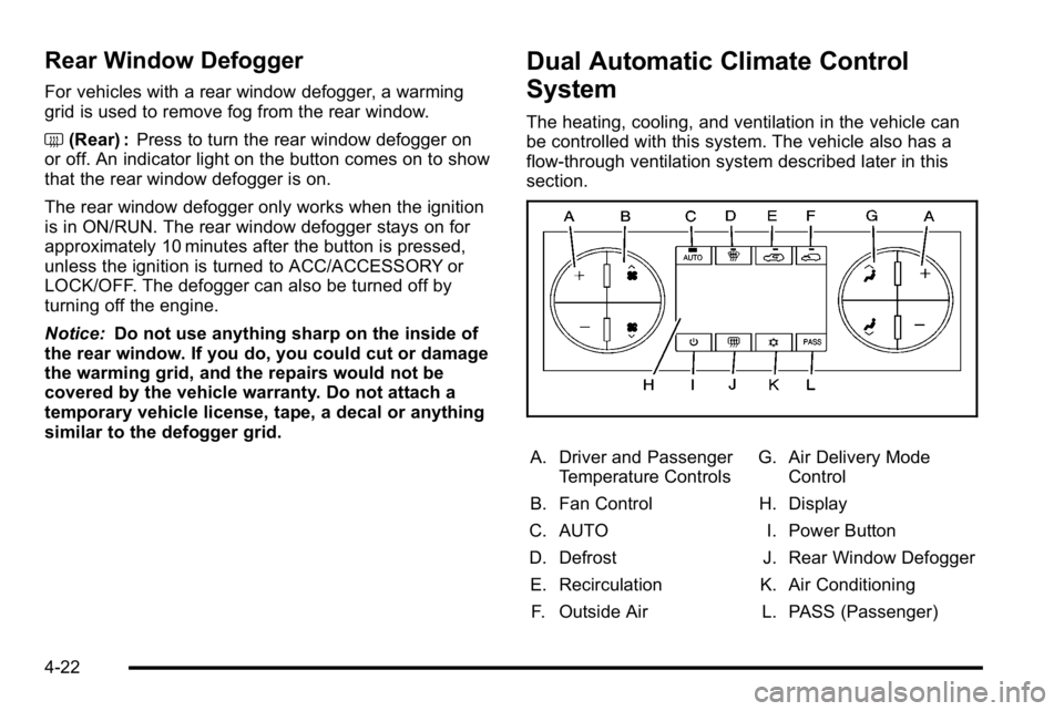
Dual Automatic Climate Control
System
The heating, cooling, and ventilation in the vehicle can
be controlled with this system. The vehicle also has a
flow-through ventilation system described later in this
section.
A. Driver and Passenger Temperature Controls
B. Fan Control
C. AUTO
D. Defrost E. Recirculation F. Outside Air G. Air Delivery Mode
Control
H. Display
I. Power Button
J. Rear Window Defogger
K. Air Conditioning L. PASS (Passenger)
4-22
Page 241 of 630
O(On/Off):Press to turn the climate control system
on or off. Outside air still enters the vehicle, and is
directed to the floor. This direction can be changed by
pressing the mode button. Recirculation can be
selected once you have selected vent or bi-level mode.
The temperature can also be adjusted using either
temperature button. If the air delivery mode or
temperature settings are adjusted with the system off,
the display illuminates briefly to show the settings and
then returns to off. The system can be turned back on
by pressing either
O,D,C,#, the defrost or the
AUTO button.
Driver and Passenger Side Temperature
Controls
The driver and passenger side temperature buttons
are used to adjust the temperature of the air coming
through the system on the driver or passenger's side of
the vehicle. The temperature can be adjusted even if
the system is turned off. This is possible since outside
air always flows through the system as the vehicle is
moving forward unless it is set to recirculation mode.
See “Recirculation” later in this section. Press the + or
−buttons to increase or decrease the
cabin temperature. The driver side or passenger side
temperature display shows the temperature setting
decreasing or increasing.
The passenger's temperature setting can be set to
match the driver's temperature setting by pressing
the PASS button and turning off the PASS indicator.
When the passenger's temperature setting is set
different than the driver's setting, the indicator on the
PASS button illuminates and both the driver side and
passenger side temperature displays are shown.
When in defrost mode the passenger temperature
setting cannot be changed.
4-23
Page 242 of 630

Automatic Operation
AUTO (Automatic) :When automatic operation is
active the system controls the inside temperature, the
air delivery, and the fan speed.
Use the steps below to place the entire system in
automatic mode:
1. Press the AUTO button. When AUTO is selected, the display changes to
show the current temperature(s) and AUTO is lit on
the display. The current air delivery mode and fan
speed are also displayed for about 5 seconds.
When AUTO is selected, the air conditioning
operation and air inlet are automatically controlled.
The air conditioning compressor may run when
the outside temperature is above freezing. The air
inlet will normally be set to outside air. If it is hot
outside, the air inlet may automatically switch to
the recirculate mode to help quickly cool down the
air inside the vehicle. The light on the button
comes on in recirculation. 2. Set the driver's and passenger's temperature.
To find your comfort setting, start with a 23°C
(74°F) temperature setting and allow about
20 minutes for the system to regulate. Use the
driver or passenger temperature buttons to
adjust the temperature setting as necessary. If a
temperature setting of 15°C (60°F) is chosen, the
system remains at the maximum cooling setting.
If a temperature setting of 32°C (90°F) is chosen,
the system remains at the maximum heat setting.
Choosing either maximum setting will not cause
the vehicle to heat or cool any faster.
Do not cover the solar sensor located on the top of the
instrument panel near the windshield. This sensor
regulates air temperature based on sun load. For more
information on the solar sensor, see “Sensors”later in
this section.
To avoid blowing cold air in cold weather, the system
delays turning the fan on until warm air is available.
The length of delay depends on the engine coolant
temperature. Pressing the fan switch overrides this
delay and changes the fan to a selected speed.
4-24