Page 89 of 210

88
SAFETY
STARTING
AND DRIVING
WARNING
LIGHTS AND
MESSAGES
IN AN
EMERGENCY
MAINTENANCE
AND CARE
TECHNICAL
SPECIFICATIONS
ALPHABETICAL
INDEX
DASHBOARD
AND CONTROLS
PARKING
SENSORS
(where provided)
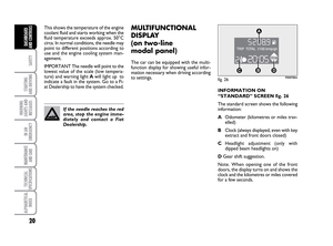
Parking sensors are located in the rear
bumper fig. 127and their function is to
inform the driver, through an intermittent
buzzer, about the presence of obstacles
behind the car.
ACTIVATION
The sensors are automatically activated
when the reverse gear is engaged.
As the distance from the obstacle behind
the car decreases, the acoustic alarm be-
comes more frequent. BUZZER WARNINGS
When the reverse gear is engaged an in-
termittent acoustic signal is automatically
activated.
The acoustic signal:
❒becomes louder as the reduction of
distance between the car and the ob-
stacle decreases;
❒becomes continuous when the dis-
tance between the car and the obsta-
cle is less that 30 cm and stops imme-
diately if the distance raises;
fig. 127F0H0744m
❒is constant if the distance is unvaried;
if this situation concerns the side sen-
sors, the buzzer will stop after about
3 seconds to avoid, for example, warn-
ing indications in the event of ma-
noeuvres along walls.
Detection distances
The central range of action varies ac-
cording to the version: the range is equal
to 140 cm and to 70 cm for small sized
obstacles (or round parking posts). The
side action range is 60 cm.
If several obstacles are detected by the
sensors, only the nearest one is consid-
ered.
036-092 LUM IDEA GB 2 ed.qxd 14-01-2010 12:15 Pagina 88
Page 90 of 210

89
SAFETY
STARTING
AND DRIVING
WARNING
LIGHTS AND
MESSAGES
IN AN
EMERGENCY
MAINTENANCE
AND CARE
TECHNICAL
SPECIFICATIONS
ALPHABETICAL
INDEX
DASHBOARD
AND CONTROLS
FAILURE INDICATIONS
See the “Warning lights and messages”
chapter.
OPERATION WITH TRAILER
The system is deactivated automatically
when the trailer electric cable plug is fit-
ted into the car tow hook socket.
The sensors are automatically enabled
again when the trailer cable plug is re-
moved.It is vital that the sensors are
always clean in order for the
system to work properly.
Take great care when clean-
ing the sensors not to scratch or dam-
age them; avoid using dry, rough or
hard cloths. Clean the sensors with
clean water with the addition of car
shampoo if necessary. In washing sta-
tions, clean the sensors quickly, keep-
ing the steam jet/high pressure wash-
ing nozzles at least 10 cm away from
the sensors.
The ultimate responsibility
when parking and carrying
out other dangerous manoeuvres still
rests with the driver. Always make
sure that there are no people, ani-
mals or objects in the way when car-
rying out these manoeuvres. Parking
sensors are designed to assist drivers:
in all cases, you must always pay the
utmost attention during potentially
dangerous manoeuvres, even when
these are carried out a low speed.
WARNING
GENERAL WARNINGS
❒When parking, take the utmost care
to obstacles that may be set above or
under the sensors.
❒Objects set close to the car, under
certain circumstances are not detect-
ed and could therefore cause damages
to the car or be damaged.
❒indications sent by the sensors can be
altered by dirt, snow or ice deposit-
ed on the sensors or by ultrasound
systems (e.g.: truck pneumatic brakes
or pneumatic hammers) set nearby the
car.
036-092 LUM IDEA GB 2 ed.qxd 14-01-2010 12:15 Pagina 89
Page 91 of 210

90
SAFETY
STARTING
AND DRIVING
WARNING
LIGHTS AND
MESSAGES
IN AN
EMERGENCY
MAINTENANCE
AND CARE
TECHNICAL
SPECIFICATIONS
ALPHABETICAL
INDEX
DASHBOARD
AND CONTROLS
For diesel engines, use diesel
fuel for motor vehicles com-
pliant with EN590 European
specifications only. The use of
other products or mixtures may dam-
age the engine beyond repair and con-
sequently cause lapse of warranty in
relation to the damage caused. If you
accidentally introduce other types of
fuel into the tank, do not start the en-
gine. Empty the tank. If the engine has
run, even for a very short time, you will
need to have the entire fuel system
emptied in addition to the tank.
REFUELLING
PETROL ENGINES
Use only unleaded petrol.
To avoid mistakes, the diameter of the fu-
el filler is too small to introduce the beak
of a leaded petrol pump. The petrol oc-
tane rating (RON) must not be lower than
95.
IMPORTANT An inefficient catalyst leads
to harmful exhaust emissions, thus con-
tributing to air pollution.
IMPORTANT Never use leaded petrol,
even in small amount or in an emergency,
as this would damage the catalyst beyond
repair.MULTIJET ENGINES
Operation at low temperatures
If the outside temperature is very low, the
diesel thickens due to the formation of
paraffin clots with consequent defective
operation of the fuel supply system.
In order to avoid these problems, differ-
ent types of diesel are distributed ac-
cording to the season: summer type, win-
ter type and arctic type (cold/ mountain
areas). If refuelling with diesel fuel whose
features are not suitable to the tempera-
ture of use, it is advisable to mix TUTELA
DIESEL ART additive in the proportions
shown on the container with the fuel.
Pour the additive into the tank before the
fuel.
When using or parking the vehicle for a
long time in the mountains or cold areas,
it is advisable to refuel using locally avail-
able fuel.
In this case, it is also advisable to keep the
tank over 50% full.REFUELLING
To fill the tank completely, top up twice
after the pump switches off. Further top
ups could cause faults in the fuel feeding
system.
036-092 LUM IDEA GB 2 ed.qxd 14-01-2010 12:15 Pagina 90
Page 92 of 210

91
SAFETY
STARTING
AND DRIVING
WARNING
LIGHTS AND
MESSAGES
IN AN
EMERGENCY
MAINTENANCE
AND CARE
TECHNICAL
SPECIFICATIONS
ALPHABETICAL
INDEX
DASHBOARD
AND CONTROLS
FUEL TANK CAP
The fuel flap is opened by the door lock-
ing system. Therefore, if the doors are
locked, press D-fig. 129to open the fu-
el flap.
For refuel, open the flap A-fig. 128then
loosen the cap C.
Cap Cis provided with a special device
Bwhich fastens it to the fuel filler com-
partment so it cannot be mislaid.
The hermetic seal may cause a slight in-
crease in pressure in the tank. A suction
noise when you release the cap is there-
fore entirely normal.
fig. 128F0H0125m
HATCHBACK EMERGENCY
OPENING
In case of emergency, full the cord A-fig.
131to open the fuel flap.
Remove the protection to reach the cord.
fig. 131F0H0765m
fig. 129F0H0717m
Do not place naked flames
or lit cigarettes near to the
fuel filler: fire risk. Keep your face
away from the fuel filler to prevent
breathing in harmful vapours.
WARNING
fig. 130F0H0786m
The fuel cap A-fig. 130is key-lockable
and has a catch to prevent misplacing it
(for versions/markets, where provided) B
that fastens it to the flap C; to gain access
to it, open the flap then use the ignition
key to turn counter-clocwise and re-
move the cap.
When refuelling, hook the cap to the de-
vice on the inner flap, as illustrated.
036-092 LUM IDEA GB 2 ed.qxd 14-01-2010 12:15 Pagina 91
Page 93 of 210

92
SAFETY
STARTING
AND DRIVING
WARNING
LIGHTS AND
MESSAGES
IN AN
EMERGENCY
MAINTENANCE
AND CARE
TECHNICAL
SPECIFICATIONS
ALPHABETICAL
INDEX
DASHBOARD
AND CONTROLS
PROTECTING THE
ENVIRONMENT
The devices for curtailing petrol engine
emissions are the following:
❒three-way catalytic converter;
❒Lambda sensor;
❒fuel evaporation system.
In addition, do not let the engine run, even
for a test, with one or more spark plugs
disconnected.
The devices for reducing diesel fuel engine
emissions are the following:
❒oxidising catalytic converter;
❒exhaust gas recirculation system
(E.G.R.);
❒diesel particulate filter (DPF)DPF (DIESEL
PARTICULATE FILTER)
(for 1.3 Multijet 90 HP - 1.3
Multijet 95 HP versions)
The Diesel Particulate Filter is a mechan-
ical filter, integral with the exhaust system,
that physically traps particulates present
in the exhaust gases of Diesel engines. The
diesel particular filter has been adopted to
eliminate almost totally particulates in
compliance with current / future law reg-
ulations.
During normal use of the vehicle, the en-
gine control unit records a set of data (e.g.:
travel time, type of route, temperatures,
etc.) and it will then calculate how much
particulates has been trapped by the filter.
Since this filter physically traps particulate,
it should be regenerated (cleaned) at reg-
ular intervals by burning carbon particles.
The regeneration procedure is controlled
automatically by the engine management
control unit according to the filter condi-
tions and vehicle use conditions.
The catalytic converter de-
velops high temperature dur-
ing operation. Do not park on grass,
dry leaves, pine needles or other flam-
mable material: fire risk.
WARNING
During the regeneration procedure, the
following situations may occur: limited in-
crease of idle speed, activation of electric
fan, limited increase of smoke, high tem-
peratures at the exhaust.
These are not faults; they do not impair
vehicle performance or damage the envi-
ronment. If the dedicated message is dis-
played, refer to section “Warning lights
and messages”.
036-092 LUM IDEA GB 2 ed.qxd 14-01-2010 12:15 Pagina 92
Page 94 of 210
93
STARTING
AND DRIVING
WARNING
LIGHTS AND
MESSAGES
IN AN
EMERGENCY
MAINTENANCE
AND CARE
TECHNICAL
SPECIFICATIONS
ALPHABETICAL
INDEX
DASHBOARD
AND
CONTROLSSEAT BELTS............................................................................ 94
PRETENSIONERS ................................................................. 97
CARRYING CHILDREN SAFELY ..................................... 99
“ISOFIX” CHILD RESTRAINT
ASSEMBLY SETUP ............................................................... 103
FRONT AIRBAGS................................................................. 106
FRONT AND SIDE
AIRBAGS (SIDE BAG + WINDOW BAG) .................... 108
S S
A A
F F
E E
T T
Y Y
SAFETY
093-110 LUM IDEA GB 2 ed.qxd 14-01-2010 12:16 Pagina 93
Page 95 of 210

94
STARTING
AND DRIVING
WARNING
LIGHTS AND
MESSAGES
IN AN
EMERGENCY
MAINTENANCE
AND CARE
TECHNICAL
SPECIFICATIONS
ALPHABETICAL
INDEX
DASHBOARD
AND
CONTROLS
SAFETY
SEAT BELTS
USING THE FRONT
AND SIDE REAR
SEAT BELTS
The belt should be worn keeping the chest
straight and rested against the seat back.
To fasten the seat belts, take hold the
tongue A-fig. 1and insert it into the buck-
le B, until hearing the locking click.
At removal, if it jams, let it rewind for a
short stretch, then pull it out again with-
out jerking.
Press button C-fig. 1to release the belt.
Accompany the belt while it is being re-
wound to prevent twisting.
Through the reel, the belt automatically
adapts to the body of the passenger wear-
ing it, allowing freedom of movement.
The reel may lock when the car is parked
on a steep slope: this is perfectly normal.
Furthermore, the reel mechanism locks
the belt if it is pulled and in the event of
sudden braking, collisions and on high
speed bends.The rear seat is fitted with inertial seat
belts with three anchor points and reel.
Rear seat belts must be worn as shown
in diagram D-fig. 2(five seat versions) or
as shown in diagram E-fig. 3(four seat
versions).
fig. 1F0H0126mfig. 2F0H0309m
fig. 3F0H0348m
Never press button C-fig. 1
when travelling.
WARNING
S.B.R. system
The car is fitted with a Seat Belt Reminder
system (S.B.R.), consisting of a buzzer and
a flashing warning light
ment panel which warns the driver that
the seat belt must be fastened.
093-110 LUM IDEA GB 2 ed.qxd 14-01-2010 12:16 Pagina 94
Page 96 of 210

95
STARTING
AND DRIVING
WARNING
LIGHTS AND
MESSAGES
IN AN
EMERGENCY
MAINTENANCE
AND CARE
TECHNICAL
SPECIFICATIONS
ALPHABETICAL
INDEX
DASHBOARD
AND
CONTROLS
SAFETY
The buzzer can be deactivated (until the
next engine stop) as follows:
❒fasten the driver’s seat belt;
❒turn the ignition key to MAR;
❒wait for over 20 seconds and then re-
lease one of the seat belts.
For permanent deactivation, contact the
Fiat Dealership.
The S.B.R. can only be reactivated using
the setup menu (see the “Warning lights
and messages” chapter, “Seat belt re-
minder” paragraph).
For other versions, the system must also
be reactivated by a Fiat Dealership.
ADJUSTING THE FRONT SEAT
BELT HEIGHT
(where provided)
Always adjust the seat belt height to the
passenger’s body: this precaution may
considerably reduce the risk of injury in
the event of a collision. Correct regulation is obtained when the
belt passes approximately half way be-
tween the shoulder and the neck.
To adjust, move the grip A-fig. 4of the
locking mechanism either up or down and
at the same time move the ring B to the
most suitable of the allowed positions.
USING THE MIDDLE SEAT BELT
(where provided)
The seat belt is provided with a double
buckle and fastening tab.
To prepare the seat belt for use, extract
the tabs from seat H and P-fig. 5of the
winder and pull the seat belt, making the
webbing run. Avoid twisting and tugging.
Then insert tab G-fig. 6into the buckle
Lwith button M.
Remember that in the event
of a violent collision, back
seat passengers not wearing seat belts
also represent a serious danger for
the front seat passengers.
WARNING
The height of the seat belts
must be adjusted with the
car at a standstill.
WARNING
After adjustment, always
check that the cursor to
which the ring is fastened is locked
in one of the set positions. Release
the grip and push downwards to en-
able the locking device to click if the
grip has not been released in one of
the possible positions.
WARNING
fig. 4F0H0128m
093-110 LUM IDEA GB 2 ed.qxd 14-01-2010 12:16 Pagina 95