Page 81 of 210

80
SAFETY
STARTING
AND DRIVING
WARNING
LIGHTS AND
MESSAGES
IN AN
EMERGENCY
MAINTENANCE
AND CARE
TECHNICAL
SPECIFICATIONS
ALPHABETICAL
INDEX
DASHBOARD
AND CONTROLS
BONNET
OPENING THE BONNET
Proceed as follows:
❒pull lever A-fig. 118in the direction
of the arrow;
❒move lever B-fig. 119 in the direc-
tion of the arrow;
❒lift the bonnet and at the same time
release the rod C-fig. 120from the
catch, then fit end Dof the rod into
the bonnet recess E.
IMPORTANT Before opening the bonnet,
check that windscreen wiper arms are not
lifted from the windscreen.
The bonnet must always be
perfectly closed while trav-
elling for reasons of safety. Make sure
that the bonnet is perfectly closed
and that the lock is engaged. If you
discover that the bonnet is not per-
fectly closed while travelling, stop im-
mediately and close the bonnet in the
correct manner.
WARNING
fig. 118F0H0113m
fig. 119F0H0743mfig. 120F0H0115m
CLOSING THE BONNET
Proceed as follows:
❒hold the bonnet up with one hand and
with the other remove rod C-
fig. 120from recess Dand fit it back
into its catch E;❒lower the bonnet to approximately 20
centimetres from the engine com-
partment and let it come down. Make
sure that the bonnet is completely
closed and not only fastened by the
safety catch by trying to open it. If it
is not perfectly closed, open the bon-
net and repeat the procedure. No not
simply press it.
036-092 LUM IDEA GB 2 ed.qxd 14-01-2010 12:15 Pagina 80
Page 82 of 210
81
SAFETY
STARTING
AND DRIVING
WARNING
LIGHTS AND
MESSAGES
IN AN
EMERGENCY
MAINTENANCE
AND CARE
TECHNICAL
SPECIFICATIONS
ALPHABETICAL
INDEX
DASHBOARD
AND CONTROLS
The bonnet may drop sud-
denly if the supporting rod is
not in correct position.
WARNING
Perform these operations
when the car is stationary
only.
WARNING
IMPORTANT Always check that the bon-
net is closed properly to avoid its opening
while the vehicle is travelling.ROOF BARS
(where provided)
IMPORTANT Use of Lineaccesori Fiat
roof bars is recommended fig. 121. Fol-
low the instructions contained in the as-
sembly kit to the letter. Assembly must be
performed by qualified personnel.
IMPORTANT Never exceed the maxi-
mum allowed load in the boot (see “Tech-
nical Specifications”).
Check that the attachment fastening
screws are correctly positioned after a few
kilometres.
fig. 121F0H0248m
Never operate the sunroof
when roof bars are fitted.
036-092 LUM IDEA GB 2 ed.qxd 14-01-2010 12:15 Pagina 81
Page 83 of 210

82
SAFETY
STARTING
AND DRIVING
WARNING
LIGHTS AND
MESSAGES
IN AN
EMERGENCY
MAINTENANCE
AND CARE
TECHNICAL
SPECIFICATIONS
ALPHABETICAL
INDEX
DASHBOARD
AND CONTROLS
HEADLIGHTS
BEAM DIRECTION
Correct direction of the headlights is es-
sential for the comfort and safety of the
driver and the other road users. The head-
lights must be correctly directed to ensure
the best visibility conditions when the
headlights are on. Contact a Fiat Dealer-
ship to have the headlights properly ad-
justed.
HEADLIGHT CORRECTOR
This device works with the key at MAR
and the dipped beam headlights on. The
car will slant backwards when it is loaded,
raising the light beam. The beams must
therefore be directed again in this case.
Adjusting headlight alignment
fig. 122
To adjust, press buttons
and Òon the
control panel.
The display shows the positions during the
adjustment operation.
Position 0- one or two passengers on
front seats.
fig. 122F0H0756m
Position 1- five occupants
Position 2- five passengers + load in the
boot.
Position 3- driver + maximum admitted
load in the boot.
IMPORTANT Check beam aiming every
time the load carried changes.
ADJUSTING THE HEADLIGHTS
WHEN ABROAD
The dipped headlamps are adjusted for
service in the country where the vehicle
was originally purchased. When travelling
in countries on the other side of the road,
cover the headlight as shown in the figure.
Use non-transparent adhesive for this pur-
pose.The figures fig. 123-124 show how to
change from left-hand drive to right-hand
drive.
fig. 123F0H0118m
fig. 124F0H0119m
036-092 LUM IDEA GB 2 ed.qxd 14-01-2010 12:15 Pagina 82
Page 84 of 210

83
SAFETY
STARTING
AND DRIVING
WARNING
LIGHTS AND
MESSAGES
IN AN
EMERGENCY
MAINTENANCE
AND CARE
TECHNICAL
SPECIFICATIONS
ALPHABETICAL
INDEX
DASHBOARD
AND CONTROLS
ABS SYSTEM
If you have never driven a vehicle with
ABS before, it is advisable to perform a
few tests on slippery ground, naturally in
conditions of safety and respecting the
Highway Code of the country where you
are driving. Read the following informa-
tion carefully.
The car is fitted with an ABS braking sys-
tem, which prevents the wheels from lock-
ing when braking, makes the most of road
grip and gives the best control when
emergency braking under difficulty road
conditions.
System is completed by EBD (Electronic
Braking force Distribution), which dis-
tributes the braking action between front
and rear wheels.
IMPORTANT The braking system needs
to settle for approximately 500 km: dur-
ing this time, avoid sudden, repeated and
prolonged braking.ABS SYSTEM INTERVENTION
Intervention of the ABS is detected by a
slight pulsing of the brake pedal accom-
panied by noise: such an event indicates
that you need to adjust your speed to the
type of road on which you are travelling.
When the ABS intervenes it means that
you are approaching the grip limit be-
tween tyres and road: slow down to ex-
ploit all the available grip.
FAILURE INDICATIONS
ABS failure
ABS failure is indicated by the turning on
of warning light
>on the instrument pan-
el together with the dedicated message on
the multifunctional display (where pro-
vided), (see section “Warning lights and
messages”). In the case, the braking sys-
tem will work as normal without the ex-
tra potentials offered by the ABS system.
Drive carefully to the nearest Fiat Deal-
ership to have the system checked.EBD failure
ABS failure is indicated by the turning on
of warning light >and xon the instru-
ment panel together with the dedicated
message on the multifunctional display
(where provided), (see section “Warning
lights and messages”). In this case, the rear
wheels may suddenly lock and the vehi-
cle may swerve when braking sharply. Dri-
ve carefully to the nearest Fiat Dealership
to have the system checked.
When the ABS intervenes it
means that you are ap-
proaching the grip limit between tyres
and road: slow down to exploit all the
available grip.
WARNING
The ABS exploits the tyre-
road grip at the best, but it
cannot improve it; you should there-
fore take every care when driving on
slippery surfaces without taking un-
necessary risks.
WARNING
When the ABS cuts in, and
you feel the brake pedal pul-
sating, do not remove your foot, but
keep it pressed; in doing so you will
stop in the shortest amount of space
possible under the current road con-
ditions.
WARNING
036-092 LUM IDEA GB 2 ed.qxd 14-01-2010 12:15 Pagina 83
Page 85 of 210

84
SAFETY
STARTING
AND DRIVING
WARNING
LIGHTS AND
MESSAGES
IN AN
EMERGENCY
MAINTENANCE
AND CARE
TECHNICAL
SPECIFICATIONS
ALPHABETICAL
INDEX
DASHBOARD
AND CONTROLS
If warning light xonly lights
up on the instrument panel
(with a message on the reconfigurable
multifunctional display, where pro-
vided), stop the car immediately and
go to the nearest Fiat Dealership.
Leakage of hydraulic fluid from the
braking system will compromise func-
tionality of the braking system, either
of the conventional type or with ABS.
WARNINGEOBD SYSTEM
The EOBD system (European On Board
Diagnosis) allows continuous diagnosis of
the components of the car correlated with
emissions. It also alerts the driver, by turn-
ing on the warning light
Uon the in-
strument panel (together with relevant
message on the multifunctional display,
where provided) (see section “Warning
lights and messages”), when these condi-
tions are no longer in peak conditions.
The objective is:
❒to keep the system efficiency under
control;
❒warn when a fault causes emissions
levels to increase;
❒warn of the need to replace deterio-
rated components.
The system also has a diagnostic connec-
tor that can be interfaced with appropri-
ate tools, which makes it possible to read
the error codes stored in the control unit
together with a series of specific parame-
ters for engine operation and diagnosis.
This check can also be carried out by the
traffic police.
IMPORTANT After eliminating the in-
convenience, to check the system com-
pletely, Fiat Dealerships are obliged to run
a bench test and, if necessary, road tests
which may also call for a long journey. Go to a Fiat Dealership as
soon as possible if warning
light
Ueither does not light
up when the key is turned to
MAR to if while travelling the warning
lights comes on either steady or blink-
ing (along with a message on the mul-
tifunctional display, where provided).
The operation of warning light
Umay
be checked by the traffic police using
specific devices. Follow the laws in
force in the country where you are dri-
ving.
GSI SYSTEM
(for versions with
mechanical gearbox
only)
(where provided)
The gear shift indication makes it possible,
on cars with a manual gearbox, to suggest
the driver should change gear (higher gear:
shift up, see Fig. 1or lower gear: shift
down, see Fig. 2), through a dedicated in-
dication in the control panel. This sugges-
tion to change gear is designed to improve
consumption and ensure the best driving
style.
NOTE: the indication in the instrument
panel remains on until the driver makes
a gear change or until the driving condi-
tions return to a situation where a gear
change is not required to improve con-
sumption.
fig. a fig. b
036-092 LUM IDEA GB 2 ed.qxd 14-01-2010 12:15 Pagina 84
Page 86 of 210

Refer")
85
SAFETY
STARTING
AND DRIVING
WARNING
LIGHTS AND
MESSAGES
IN AN
EMERGENCY
MAINTENANCE
AND CARE
TECHNICAL
SPECIFICATIONS
ALPHABETICAL
INDEX
DASHBOARD
AND CONTROLS
SOUND SYSTEM
(where provided)
Refer to the supplement to this Owner’s
Handbook for operating the sound system
with CD or with CD MP3.
SOUND SYSTEM SETUP
(where provided)
The system consists of:
❒sound system power wires
❒front and rear speaker power wires
❒aerial power wire
❒2 tweeters on front pillars (30W max
power each);
❒2 mid-woofers on front doors (165
mm diameter, 40W max power each);
❒2 full-range speaker on front doors
(165 mm diameter, 40W max power
each).
Sound system installation
The sound system must be installed in the
space occupied by the central oddment
compartment fig. 125where the wiring
leads.
To extract the compartment, press in the
points shown at the retainer systems.It is advisable to have the sound system
and interference filter installed by a Fi-
at Dealership.
MOBILE PHONE SETUP
(where provided)
The mobile phone setup with
CD or CD MP3 sound system consists of:
fig. 125F0H0120m
❒a dual function aerial (sound system +
phone phone 900/1800 MHz) located
on the roof;
❒connection cables to the dual function
sound system and wiring with 10 pin
connector.The hands-free kit must be
purchased by the customer
because it must be compati-
ble with the customer’s mo-
bile phone. It is advisable to install the
microphone near the front ceiling light.
The maximum applicable
power to the aerial is 20W.
WARNING
For installing the mobile
phone and connecting to
system setup in the car, contact Fiat
Dealership to prevent any trouble
that could impair car safety.
WARNING
The connector is located between the
steering column and the central unit.
036-092 LUM IDEA GB 2 ed.qxd 14-01-2010 12:15 Pagina 85
Page 87 of 210

86
SAFETY
STARTING
AND DRIVING
WARNING
LIGHTS AND
MESSAGES
IN AN
EMERGENCY
MAINTENANCE
AND CARE
TECHNICAL
SPECIFICATIONS
ALPHABETICAL
INDEX
DASHBOARD
AND CONTROLS
ACCESSORIES
PURCHASED BY THE
OWNER
If after buying the car, you decide to install
electrical accessories that require a per-
manent electric supply (alarm, satellite an-
titheft system, etc.) or accessories that in
any case burden the electric supply, con-
tact Fiat Dealership, whose qualified per-
sonnel, besides suggesting the most suit-
able devices belonging to Lineaccessori Fi-
at, will also evaluate the overall electric
consumption, checking whether the car’s
electric system is able to withstand the
load required, or whether it needs to be
integrated with a more powerful battery.
INSTALLING
ELECTRICAL/ELECTRONIC
DEVICES
Electrical and electronic devices installed
after buying the car by after-market ser-
vice must carry the following label:
Fiat Auto S.p.A. authorises the installation
of transceiving devices provided that they
are installed by a specialised centre ac-
cording to rules of good engineering prac-
tice in compliance with the manufacturer’s
indications.IMPORTANT Traffic police may not allow
the car on the road in the event of as-
sembly of devices which imply modifica-
tions to the features of the car. This may
also cause lapse of warranty in relation to
faults caused by the change or either di-
rectly or indirectly related to it.
Fiat Auto S.p.A. shall not be liable for dam-
age caused by the installation of acces-
sories either not supplied or recom-
mended by Fiat Auto S.p.A. and/or not in-
stalled in compliance with the provided in-
structions.
RADIO TRANSMITTERS AND
CELLULAR PHONES
Radio transceiver equipment (e.g.: e-tacs
mobile phones, HAM radio systems and
the like) shall not be used inside the car
unless a separate aerial is mounted on the
roof.
IMPORTANT The use of similar devices
inside the passenger compartment (with-
out separated aerial) produces radio-fre-
quency electromagnetic fields which, am-
plified by the resonance effects inside the
passenger compartment, may cause elec-
trical systems equipping the car to mal-
function. This could compromise safety in
addition to constituting a potential hazard
for the passengers.
In addition, transmission and reception of
these devices may be affected by the
shielding effect of the car body.As concerns EC-approved mobile phones
(GSM, GPRS, UMTS), strictly comply with
the instructions for use provided by the
mobile phone’s manufacturer.
Be very careful when fitting
non-standard additional
spoilers, light alloy wheels or wheel
caps: they could reduce brake venti-
lation and consequently brake effi-
ciency in the case of repeated, violent
braking or on long downhill roads.
Make sure that nothing obstructs the
pedal stroke (mats, etc.)
WARNING
036-092 LUM IDEA GB 2 ed.qxd 14-01-2010 12:15 Pagina 86
Page 88 of 210

87
SAFETY
STARTING
AND DRIVING
WARNING
LIGHTS AND
MESSAGES
IN AN
EMERGENCY
MAINTENANCE
AND CARE
TECHNICAL
SPECIFICATIONS
ALPHABETICAL
INDEX
DASHBOARD
AND CONTROLS
DUALDRIVE ELECTRIC
POWER STEERING
The car is provided with an electric pow-
er steering system which only works with
the key at MARand the engine running.
The system called “Dualdrive” allows to
customise the effort required to turn the
steering wheel according to driving con-
ditions.
ON/OFF (CITY function)
Press CITY fig. 126in the central part of
the dashboard to turn the function on and
off.
The CITYwarning light on the instru-
ment panel will light up when the function
is on; in other versions, the message
CITYwill appear on the reconfigurable
multifunctional display.
With the CITYfunction the effort on the
steering wheel is lighter, thus facilitating
parking manoeuvres: this is particularly
useful when driving in towns.
fig. 126F0H0716m
Under no circumstances
should aftermarket opera-
tions involving steering system or
steering column modifications (e.g.:
installation of anti-theft device) be
carried out that could badly affect
performance and safety. This also
causes the warranty to become null
and void and results in vehicle non-
compliance with type-approval re-
quirements.
WARNING
The car can be driven using the mechani-
cal steering in case of failure to the elec-
tric power steering system. Take the car
to a Fiat Dealership as soon as possible.
IMPORTANT The steering may before
stiffer when parking requiring a lot of
steering. This is normal and caused by the
electric control motor overheating sys-
tem. No repairs are needed. The power
steering system will start working prop-
erly again the next time the car is used.
Before starting any mainte-
nance operation, stop the
engine and remove the key from the
ignition switch to operate the steer-
ing lock, particularly when the car is
lifted off the ground. If this is not pos-
sible (i.e. if the key must be kept in
the MAR position or the engine must
be kept running), remove the main
electric power steering system fuse.
WARNING
FAILURE INDICATIONS
Electric power steering failure is indicated
by the turning on of warning light
gon
the instrument panel together with the
dedicated message on the reconfigurable
multifunctional display (where provided),
(see section “Warning lights and mes-
sages”).
036-092 LUM IDEA GB 2 ed.qxd 14-01-2010 12:15 Pagina 87
 1
1 2
2 3
3 4
4 5
5 6
6 7
7 8
8 9
9 10
10 11
11 12
12 13
13 14
14 15
15 16
16 17
17 18
18 19
19 20
20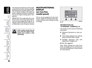 21
21 22
22 23
23 24
24 25
25 26
26 27
27 28
28 29
29 30
30 31
31 32
32 33
33 34
34 35
35 36
36 37
37 38
38 39
39 40
40 41
41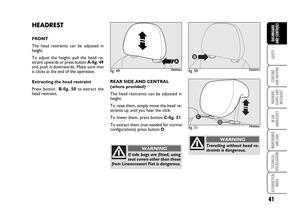 42
42 43
43 44
44 45
45 46
46 47
47 48
48 49
49 50
50 51
51 52
52 53
53 54
54 55
55 56
56 57
57 58
58 59
59 60
60 61
61 62
62 63
63 64
64 65
65 66
66 67
67 68
68 69
69 70
70 71
71 72
72 73
73 74
74 75
75 76
76 77
77 78
78 79
79 80
80 81
81 82
82 83
83 84
84 85
85 86
86 87
87 88
88 89
89 90
90 91
91 92
92 93
93 94
94 95
95 96
96 97
97 98
98 99
99 100
100 101
101 102
102 103
103 104
104 105
105 106
106 107
107 108
108 109
109 110
110 111
111 112
112 113
113 114
114 115
115 116
116 117
117 118
118 119
119 120
120 121
121 122
122 123
123 124
124 125
125 126
126 127
127 128
128 129
129 130
130 131
131 132
132 133
133 134
134 135
135 136
136 137
137 138
138 139
139 140
140 141
141 142
142 143
143 144
144 145
145 146
146 147
147 148
148 149
149 150
150 151
151 152
152 153
153 154
154 155
155 156
156 157
157 158
158 159
159 160
160 161
161 162
162 163
163 164
164 165
165 166
166 167
167 168
168 169
169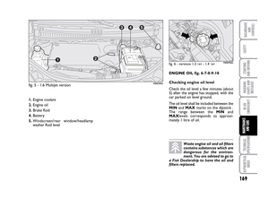 170
170 171
171 172
172 173
173 174
174 175
175 176
176 177
177 178
178 179
179 180
180 181
181 182
182 183
183 184
184 185
185 186
186 187
187 188
188 189
189 190
190 191
191 192
192 193
193 194
194 195
195 196
196 197
197 198
198 199
199 200
200 201
201 202
202 203
203 204
204 205
205 206
206 207
207 208
208 209
209