2010 CHEVROLET EQUINOX light
[x] Cancel search: lightPage 297 of 394
Vehicle Care 9-29
Notice:Do not cover a headlamp
to improve beam cut-off when
aiming. Covering a headlamp may
cause excessive heat build-up
which may cause damage to the
headlamp.
6. Turn on the low-beam
headlamps and place a piece of
cardboard or equivalent in front
of the headlamp not being
adjusted. This allows only the
beam of light from the headlamp
being adjusted to be seen on the
flat surface.
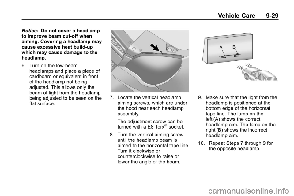
7. Locate the vertical headlampaiming screws, which are under
the hood near each headlamp
assembly.
The adjustment screw can be
turned with a E8 Torx
®socket.
8. Turn the vertical aiming screw until the headlamp beam is
aimed to the horizontal tape line.
Turn it clockwise or
counterclockwise to raise or
lower the angle of the beam.
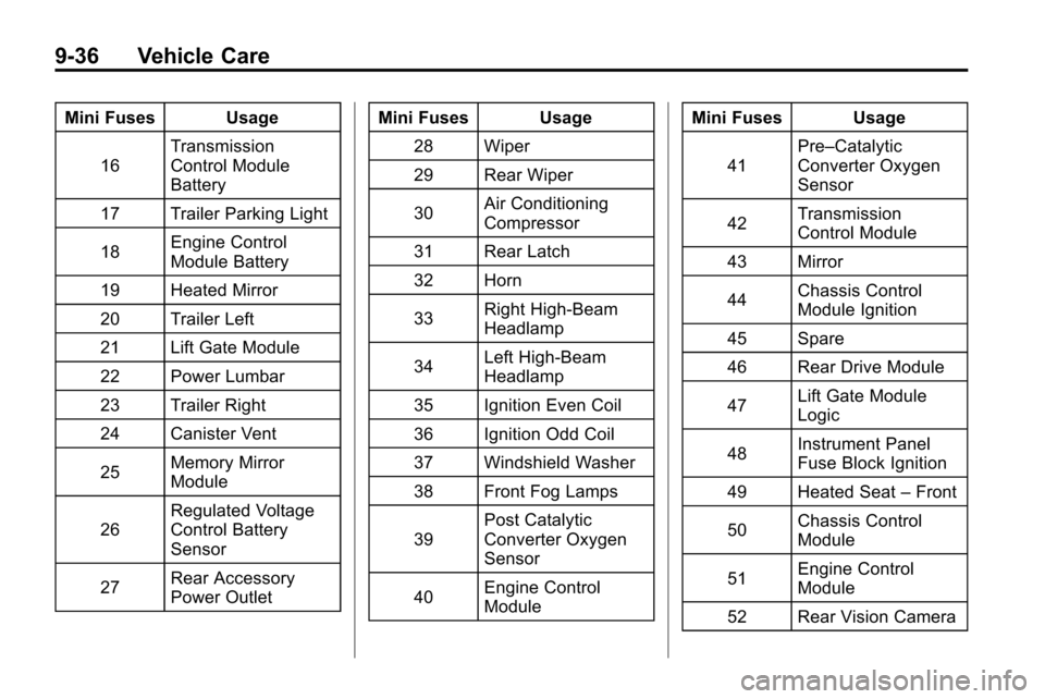
9. Make sure that the light from theheadlamp is positioned at the
bottom edge of the horizontal
tape line. The lamp on the
left (A) shows the correct
headlamp aim. The lamp on the
right (B) shows the incorrect
headlamp aim.
10. Repeat Steps 7 through 9 for the opposite headlamp.
Page 304 of 394
9-36 Vehicle Care
Mini Fuses Usage16 Transmission
Control Module
Battery
17 Trailer Parking Light
18 Engine Control
Module Battery
19 Heated Mirror
20 Trailer Left
21 Lift Gate Module
22 Power Lumbar
23 Trailer Right
24 Canister Vent
25 Memory Mirror
Module
26 Regulated Voltage
Control Battery
Sensor
27 Rear Accessory
Power Outlet Mini Fuses Usage
28 Wiper
29 Rear Wiper
30 Air Conditioning
Compressor
31 Rear Latch
32 Horn
33 Right High‐Beam
Headlamp
34 Left High‐Beam
Headlamp
35 Ignition Even Coil
36 Ignition Odd Coil
37 Windshield Washer
38 Front Fog Lamps
39 Post Catalytic
Converter Oxygen
Sensor
40 Engine Control
Module Mini Fuses Usage
41 Pre–Catalytic
Converter Oxygen
Sensor
42 Transmission
Control Module
43 Mirror
44 Chassis Control
Module Ignition
45 Spare
46 Rear Drive Module
47 Lift Gate Module
Logic
48 Instrument Panel
Fuse Block Ignition
49 Heated Seat –Front
50 Chassis Control
Module
51 Engine Control
Module
52 Rear Vision Camera
Page 312 of 394
9-44 Vehicle Care
Curb Weight:The weight of a
motor vehicle with standard and
optional equipment including the
maximum capacity of fuel, oil,
and coolant, but without
passengers and cargo.
DOT Markings
:A code molded
into the sidewall of a tire
signifying that the tire is in
compliance with the U.S.
Department of Transportation
(DOT) motor vehicle safety
standards. The DOT code
includes the Tire Identification
Number (TIN), an alphanumeric
designator which can also
identify the tire manufacturer,
production plant, brand, and
date of production.
GVWR
:Gross Vehicle Weight
Rating. See Vehicle Load Limits
on page 8‑24. GAWR FRT
:Gross Axle Weight
Rating for the front axle. See
Vehicle Load Limits
on
page 8‑24
.
GAWR RR
:Gross Axle Weight
Rating for the rear axle. See
Vehicle Load Limits
on
page 8‑24
.
Intended Outboard Sidewall
:
The side of an asymmetrical tire,
that must always face outward
when mounted on a vehicle.
Kilopascal (kPa)
:The metric
unit for air pressure.
Light Truck (LT‐Metric) Tire
:A
tire used on light duty trucks and
some multipurpose passenger
vehicles.
Load Index
:An assigned
number ranging from 1 to 279
that corresponds to the load
carrying capacity of a tire. Maximum Inflation Pressure
:
The maximum air pressure to
which a cold tire can be inflated.
The maximum air pressure is
molded onto the sidewall.
Maximum Load Rating
:The
load rating for a tire at the
maximum permissible inflation
pressure for that tire.
Maximum Loaded Vehicle
Weight
:The sum of curb
weight, accessory weight,
vehicle capacity weight, and
production options weight.
Normal Occupant Weight
:The
number of occupants a vehicle
is designed to seat multiplied by
68 kg (150 lbs). See Vehicle
Load Limits
on page 8‑24.
Occupant Distribution
:
Designated seating positions.
Page 313 of 394
Vehicle Care 9-45
Outward Facing Sidewall:The
side of an asymmetrical tire that
has a particular side that faces
outward when mounted on a
vehicle. The side of the tire that
contains a whitewall, bears
white lettering, or bears
manufacturer, brand, and/or
model name molding that is
higher or deeper than the same
moldings on the other sidewall
of the tire.
Passenger (P-Metric) Tire
:A
tire used on passenger cars and
some light duty trucks and
multipurpose vehicles.
Recommended Inflation
Pressure
:Vehicle
manufacturer's recommended
tire inflation pressure as shown
on the tire placard. See Tire
Pressure
on page 9‑46and
Vehicle Load Limits
on
page 8‑24
. Radial Ply Tire
:A pneumatic
tire in which the ply cords that
extend to the beads are laid at
90 degrees to the centerline of
the tread.
Rim
:A metal support for a tire
and upon which the tire beads
are seated.
Sidewall
:The portion of a tire
between the tread and the bead.
Speed Rating
:An
alphanumeric code assigned to
a tire indicating the maximum
speed at which a tire can
operate.
Traction
:The friction between
the tire and the road surface.
The amount of grip provided.
Tread
:The portion of a tire that
comes into contact with
the road. Treadwear Indicators
:Narrow
bands, sometimes called wear
bars, that show across the tread
of a tire when only 1.6 mm
(1/16 inch) of tread remains.
See When It Is Time for New
Tires
on page 9‑53.
UTQGS (Uniform Tire Quality
Grading Standards)
:A tire
information system that provides
consumers with ratings for a
tire's traction, temperature,
and treadwear. Ratings are
determined by tire
manufacturers using
government testing procedures.
The ratings are molded into the
sidewall of the tire. See Uniform
Tire Quality Grading
on
page 9‑56
.
Page 317 of 394
Vehicle Care 9-49
Tire Pressure Monitor
Operation
This vehicle may have a Tire
Pressure Monitor System (TPMS).
The TPMS is designed to warn the
driver when a low tire pressure
condition exists. TPMS sensors are
mounted onto each tire and wheel
assembly, excluding the spare tire
and wheel assembly. The TPMS
sensors monitor the air pressure in
the vehicle's tires and transmits the
tire pressure readings to a receiver
located in the vehicle.
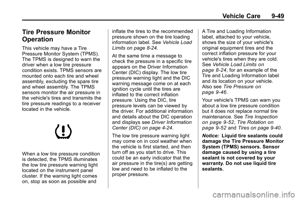
When a low tire pressure condition
is detected, the TPMS illuminates
the low tire pressure warning light
located on the instrument panel
cluster. If the warning light comes
on, stop as soon as possible andinflate the tires to the recommended
pressure shown on the tire loading
information label. See
Vehicle Load
Limits on page 8‑24.
At the same time a message to
check the pressure in a specific tire
appears on the Driver Information
Center (DIC) display. The low tire
pressure warning light and the DIC
warning message come on at each
ignition cycle until the tires are
inflated to the correct inflation
pressure. Using the DIC, tire
pressure levels can be viewed by
the driver. For additional information
and details about the DIC operation
and displays see Driver Information
Center (DIC) on page 4‑24.
The low tire pressure warning light
may come on in cool weather when
the vehicle is first started, and then
turn off as you start to drive. This
could be an early indicator that the
air pressure in the tire(s) are getting
low and need to be inflated to the
proper pressure. A Tire and Loading Information
label, attached to your vehicle,
shows the size of your vehicle's
original equipment tires and the
correct inflation pressure for your
vehicle's tires when they are cold.
See
Vehicle Load Limits
on
page 8‑24, for an example of the
Tire and Loading Information label
and its location on your vehicle.
Also see Tire Pressure
on
page 9‑46.
Your vehicle's TPMS can warn you
about a low tire pressure condition
but it does not replace normal tire
maintenance. See Tire Inspection
on page 9‑52,Tire Rotationon
page 9‑52and Tires on page 9‑40.
Notice: Liquid tire sealants could
damage the Tire Pressure Monitor
System (TPMS) sensors. Sensor
damage caused by using a tire
sealant is not covered by your
warranty. Do not use liquid tire
sealants.
Page 318 of 394
9-50 Vehicle Care
TPMS Malfunction Light and
Message
The TPMS will not function properly
if one or more of the TPMS sensors
are missing or inoperable. When the
system detects a malfunction, the
low tire warning light flashes for
about one minute and then stays on
for the remainder of the ignition
cycle. A DIC warning message is
also displayed. The low tire warning
light and DIC warning message
come on at each ignition cycle until
the problem is corrected. Some of
the conditions that can cause the
malfunction light and DIC message
to come on are:
.One of the road tires has been
replaced with the spare tire. The
spare tire does not have a
TPMS sensor. The TPMS
malfunction light and DIC
message should go off once you
re‐install the road tire containing
the TPMS sensor.
.The TPMS sensor matching
process was started but not
completed or not completed
successfully after rotating the
vehicle's tires. The DIC message
and TPMS malfunction light
should go off once the TPMS
sensor matching process is
performed successfully. See
“TPMS Sensor Matching
Process”later in this section.
.One or more TPMS sensors are
missing or damaged. The DIC
message and the TPMS
malfunction light should go off
when the TPMS sensors are
installed and the sensor
matching process is performed
successfully. See your dealer for
service.
.Replacement tires or wheels do
not match your vehicle's original
equipment tires or wheels. Tires
and wheels other than those
recommended for your vehicle
could prevent the TPMS from
functioning properly. See Buying
New Tires on page 9‑54.
.Operating electronic devices or
being near facilities using radio
wave frequencies similar to the
TPMS could cause the TPMS
sensors to malfunction.
If the TPMS is not functioning it
cannot detect or signal a low tire
condition. See your dealer for
service if the TPMS malfunction
light and DIC message comes on
and stays on.
TPMS Sensor Matching
Process
Each TPMS sensor has a unique
identification code. Any time you
rotate your vehicle's tires or replace
one or more of the TPMS sensors,
the identification codes will need to
be matched to the new tire/wheel
position. The sensors are matched
to the tire/wheel positions in the
following order: driver side front tire,
passenger side front tire, passenger
side rear tire, and driver side rear
tire using a TPMS diagnostic tool.
See your dealer for service.
Page 324 of 394
9-56 Vehicle Care
Uniform Tire Quality
Grading
Quality grades can be found
where applicable on the tire
sidewall between tread shoulder
and maximum section width. For
example:
Treadwear 200 Traction AA
Temperature A
The following information relates
to the system developed by the
United States National Highway
Traffic Safety Administration
(NHTSA), which grades tires by
treadwear, traction, and
temperature performance. This
applies only to vehicles sold in
the United States. The grades
are molded on the sidewalls of
most passenger car tires. The
Uniform Tire Quality Grading(UTQG) system does not apply
to deep tread, winter-type snow
tires, space-saver, or temporary
use spare tires, tires with
nominal rim diameters of
10 to 12 inches (25 to 30 cm),
or to some limited-production
tires.
While the tires available on
General Motors passenger cars
and light trucks may vary with
respect to these grades, they
must also conform to federal
safety requirements and
additional General Motors Tire
Performance Criteria (TPC)
standards.
All Passenger Car Tires Must
Conform to Federal Safety
Requirements In Addition To
These Grades.
Treadwear
The treadwear grade is a
comparative rating based on the
wear rate of the tire when tested
under controlled conditions on a
specified government test
course. For example, a tire
graded 150 would wear one and
a half (1½) times as well on the
government course as a tire
graded 100. The relative
performance of tires depends
upon the actual conditions of
their use, however, and may
depart significantly from the
norm due to variations in
driving habits, service practices
and differences in road
characteristics and climate.
Page 337 of 394
Vehicle Care 9-69
Jump Starting
Jump starting can be used on
vehicles with run‐down batteries by
using jumper cables and another
vehicle.
{WARNING
Batteries can hurt you. They can
be dangerous because:
.They contain acid that can
burn you.
.They contain gas that can
explode or ignite.
.They contain enough
electricity to burn you.
If you do not follow these steps
exactly, some or all of these
things can hurt you.
{WARNING
Using an open flame near a
battery can cause battery gas to
explode. People have been hurt
doing this, and some have been
blinded. Use a flashlight if you
need more light.
Be sure the battery has enough
water. You do not need to add
water to the battery installed in
your new vehicle. But if a battery
has filler caps, be sure the right
amount of fluid is there. If it is low,
add water to take care of that
first. If you do not, explosive gas
could be present.
Battery fluid contains acid that
can burn you. Do not get it on
you. If you accidentally get it in
your eyes or on your skin, flush
the place with water and get
medical help immediately. Be sure to use the following steps to
do it safely. Ignoring these steps
could result in costly damage to the
vehicle that would not be covered
by the warranty.
Trying to start the vehicle by
pushing or pulling it will not work,
and it could damage the vehicle.
Notice:
If you leave the radio or
other accessories on during the
jump starting procedure, they
could be damaged. The repairs
would not be covered by the
warranty. Always turn off the
radio and other accessories when
jump starting the vehicle.
Notice: If the jumper cables are
connected or removed in the
wrong order, electrical shorting
may occur and damage the
vehicle. The repairs would not be
covered by the vehicle warranty.
Always connect and remove the
jumper cables in the correct
order, making sure that the
cables do not touch each other or
other metal.