Page 293 of 394

Vehicle Care 9-25
What to Use
Refer to the Maintenance Schedule
to determine what kind of lubricant
to use. SeeRecommended Fluids
and Lubricants on page 10‑7.
Starter Switch Check
{WARNING
When you are doing this
inspection, the vehicle could
move suddenly. If the vehicle
moves, you or others could be
injured.
1. Before starting this check, be sure there is enough room
around the vehicle.
2. Firmly apply both the parking brake and the regular brake.
See Parking Brake
on
page 8‑40.
Do not use the accelerator
pedal, and be ready to turn off
the engine immediately if it
starts. 3. Try to start the engine in each
gear. The vehicle should start
only in P (Park) or N (Neutral).
If the vehicle starts in any other
position, contact your dealer for
service.
Automatic Transmission
Shift Lock Control
System Check
{WARNING
When you are doing this
inspection, the vehicle could
move suddenly. If the vehicle
moves, you or others could be
injured.
1. Before starting this check, be sure there is enough room
around the vehicle. It should be
parked on a level surface.
2. Firmly apply the parking brake. See Parking Brake
on
page 8‑40. Be ready to apply the regular
brake immediately if the vehicle
begins to move.
3. With the engine off, turn the ignition to ON/RUN, but do not
start the engine. Without
applying the regular brake, try to
move the shift lever out of
P (Park) with normal effort. If the
shift lever moves out of P (Park),
contact your dealer for service.
Ignition Transmission
Lock Check
While parked, and with the parking
brake set, try to turn the ignition to
LOCK/OFF in each shift lever
position.
.The ignition should turn to
LOCK/OFF only when the shift
lever is in P (Park).
.The ignition key should come
out only in LOCK/OFF.
Contact your dealer if service is
required.
Page 294 of 394

9-26 Vehicle Care
Park Brake and P (Park)
Mechanism Check
{WARNING
When you are doing this check,
the vehicle could begin to move.
You or others could be injured
and property could be damaged.
Make sure there is room in front
of the vehicle in case it begins to
roll. Be ready to apply the regular
brake at once should the vehicle
begin to move.
Park on a fairly steep hill, with the
vehicle facing downhill. Keeping
your foot on the regular brake, set
the parking brake.
.To check the parking brake's
holding ability: With the engine
running and the transmission in
N (Neutral), slowly remove foot
pressure from the regular brake
pedal. Do this until the vehicle is
held by the parking brake only.
.To check the P (Park)
mechanism's holding ability:
With the engine running, shift to
P (Park). Then release the
parking brake followed by the
regular brake.
Contact your dealer if service is
required.
Wiper Blade Replacement
Windshield wiper blades should be
inspected for wear and cracking.
See Scheduled Maintenance
on
page 10‑2for more information.
Replacement blades come in
different types and are removed in
different ways. For proper type and
length, see Maintenance
Replacement Parts on page 10‑9.
Notice: Allowing the wiper blade
arm to touch the windshield when
no wiper blade is installed could
damage the windshield. Any
damage that occurs would not be
covered by your warranty. Do not
allow the wiper blade arm to
touch the windshield.
Front Wiper Blade
Replacement
To replace the front wiper blades:
1. Lift the wiper arm from the windshield until no further
movement is possible.
2. Press the square button on thetop side, at the end of the wiper
arm, and pull the wiper blade out
of the end of the wiper arm.
3. Install the wiper blade connector by sliding into the end of the
wiper arm until the square button
on the wiper blade clicks into
place with the wiper arm.
4. Place the wiper arm with the wiper blade in place back on the
windshield.
Page 302 of 394

9-34 Vehicle Care
Replacement Bulbs
Exterior LampBulb
Number
Back-Up Lamp 921
Fog Lamp Front H11
Headlamp
High Beam HB3
Headlamp
Low Beam H11
License Plate Lamp W5WLL
Parking Lamp/Turn
Signal Front T20
Sidemarker Front
and Rear 194
Taillamp/Turn Signal
Lamp/Stop Lamp 3157K
For replacement bulbs not listed
here, contact your dealer.
Electrical System
Fuses
The wiring circuits in the vehicle are
protected from short circuits by
fuses. This greatly reduces the
chance of damage caused by
electrical problems.
Look at the silver-colored band
inside the fuse. If the band is broken
or melted, replace the fuse. Be sure
to replace a bad fuse with a new
one of the identical size and rating.
There are two fuse blocks in the
vehicle: one in the engine
compartment and one in the
instrument panel.
There is a fuse puller located in the
engine compartment fuse block.
See Engine Compartment Fuse
Block
on page 9‑34. It can be used
to easily remove fuses from the fuse
block.
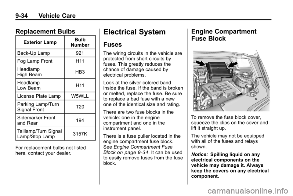
Engine Compartment
Fuse Block
To remove the fuse block cover,
squeeze the clips on the cover and
lift it straight up.
The vehicle may not be equipped
with all of the fuses and relays
shown.
Notice: Spilling liquid on any
electrical components on the
vehicle may damage it. Always
keep the covers on any electrical
component.
Page 303 of 394
Vehicle Care 9-35
Engine Compartment Fuse Block
J-Case Fuses Usage
1 Cool Fan 1
2 Cool Fan 2
3 Rear Defog J-Case
Fuses Usage
4 Power Windows
–
Right
5 Memory Seat
Module J-Case
Fuses Usage
6 Power Seat –Left
7 Instrument Panel
Fuse Block 1
8 Instrument Panel
Fuse Block 2
9 Starter
10 Brake Booster 11 Sunroof
12 Antilock Brake
System Pump
13 Instrument Panel
Fuse Block 3
14 Power Windows
–
Left
15 Antilock Brake
System Module
Page 304 of 394
9-36 Vehicle Care
Mini Fuses Usage16 Transmission
Control Module
Battery
17 Trailer Parking Light
18 Engine Control
Module Battery
19 Heated Mirror
20 Trailer Left
21 Lift Gate Module
22 Power Lumbar
23 Trailer Right
24 Canister Vent
25 Memory Mirror
Module
26 Regulated Voltage
Control Battery
Sensor
27 Rear Accessory
Power Outlet Mini Fuses Usage
28 Wiper
29 Rear Wiper
30 Air Conditioning
Compressor
31 Rear Latch
32 Horn
33 Right High‐Beam
Headlamp
34 Left High‐Beam
Headlamp
35 Ignition Even Coil
36 Ignition Odd Coil
37 Windshield Washer
38 Front Fog Lamps
39 Post Catalytic
Converter Oxygen
Sensor
40 Engine Control
Module Mini Fuses Usage
41 Pre–Catalytic
Converter Oxygen
Sensor
42 Transmission
Control Module
43 Mirror
44 Chassis Control
Module Ignition
45 Spare
46 Rear Drive Module
47 Lift Gate Module
Logic
48 Instrument Panel
Fuse Block Ignition
49 Heated Seat –Front
50 Chassis Control
Module
51 Engine Control
Module
52 Rear Vision Camera
Page 305 of 394
Vehicle Care 9-37
Midi Fuse Usage53 Electric Power
Steering
Micro
Relays Usage
54 Rear Defogger
55 Cooling Fan Low
56 Head Lamp
High Beam
57 Cooling Fan Control
58 Wiper On/Off
Control
59 Air Conditioning
Compressor
60 Wiper Speed
61 Fog Lamp
62 Engine Control
63 Starter
64 Run/Crank Mini Relays Usage
65 Cooling Fan High
66 Brake Booster
Instrument Panel Fuse
Block
The instrument panel fuse block
is located on the passenger
side panel of the center console.
To access the fuses, open the fuse
panel door from the passenger side
by pulling it out. To reinstall the door, insert the tabs
on the bottom of the door into the
console first, then push the door
back into its original location.
The vehicle may not be equipped
with all of the fuses and relays
shown.
Page 310 of 394

9-42 Vehicle Care
compact spare tire, see
Compact Spare Tire
on
page 9‑68
and If a Tire Goes Flat
on page 9‑59.
(C) Tire Identification Number
(TIN)
:The letters and numbers
following the DOT (Department
of Transportation) code is the
Tire Identification Number (TIN).
The TIN shows the
manufacturer and plant code,
tire size, and date the tire was
manufactured. The TIN is
molded onto both sides of the
tire, although only one side may
have the date of manufacture.
(D) Maximum Cold Inflation
Load Limit
:Maximum load that
can be carried and the
maximum pressure needed to
support that load. (E) Tire Inflation
:The
temporary use tire or compact
spare tire should be inflated to
420 kPa (60 psi). For more
information on tire pressure and
inflation see Tire Pressure
on
page 9‑46
.
(F) Tire Size
:A combination of
letters and numbers define a
tire's width, height, aspect ratio,
construction type, and service
description. The letter T as the
first character in the tire size
means the tire is for temporary
use only.
(G) TPC Spec (Tire
Performance Criteria
Specification)
:Original
equipment tires designed to
GM's specific tire performance
criteria have a TPC specification
code molded onto the sidewall.
GM's TPC specifications meet or
exceed all federal safety
guidelines.
Tire Designations
Tire Size
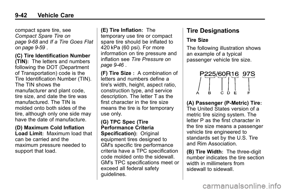
The following illustration shows
an example of a typical
passenger vehicle tire size.
(A) Passenger (P‐Metric) Tire:
The United States version of a
metric tire sizing system. The
letter P as the first character in
the tire size means a passenger
vehicle tire engineered to
standards set by the U.S. Tire
and Rim Association.
(B) Tire Width
:The three‐digit
number indicates the tire section
width in millimeters from
sidewall to sidewall.
Page 319 of 394

Vehicle Care 9-51
The TPMS sensors can also be
matched to each tire/wheel position
by increasing or decreasing the
tire's air pressure. If increasing the
tire's air pressure, do not exceed
the maximum inflation pressure
indicated on the tire's sidewall.
To decrease air-pressure out of a
tire you can use the pointed end of
the valve cap, a pencil-style air
pressure gage, or a key.
You have two minutes to match the
first tire/wheel position, and
five minutes overall to match all four
tire/wheel positions. If it takes longer
than two minutes, to match the first
tire and wheel, or more than
five minutes to match all four tire
and wheel positions the matching
process stops and you need to
start over.The TPMS sensor matching process
is outlined below:
1. Set the parking brake.
2. Turn the ignition to ON/RUN with
the engine off.
3. Use the MENU button to select the Vehicle Information Menu in
the Driver Information Center
(DIC). Use the arrow keys to
scroll to the Tire Pressure
screen.
4. Press the SET/CLR button to begin the sensor matching
process.
A message asking if you are
sure you want to begin this
process should appear.
5. Press the SET/CLR button again to confirm the selection.
The horn sounds twice to signal
the receiver is in relearn mode
and the Tire Learning Active
message displays on the DIC
screen. 6. Start with the driver side
front tire.
7. Remove the valve cap from the valve cap stem. Activate the
TPMS sensor by increasing or
decreasing the tire's air pressure
for five seconds, or until a horn
chirp sounds. The horn chirp,
which may take up to
30 seconds to sound, confirms
that the sensor identification
code has been matched to this
tire and wheel position.
8. Proceed to the passenger side front tire, and repeat the
procedure in Step 7.
9. Proceed to the passenger side rear tire, and repeat the
procedure in Step 7.