2010 CADILLAC ESCALADE brake light
[x] Cancel search: brake lightPage 431 of 616
Two-wheel-drive vehicles should not be towed withthe rear wheels on the ground. Two-wheel-drivetransmissions have no provisions for internal lubricationwhile being towed.
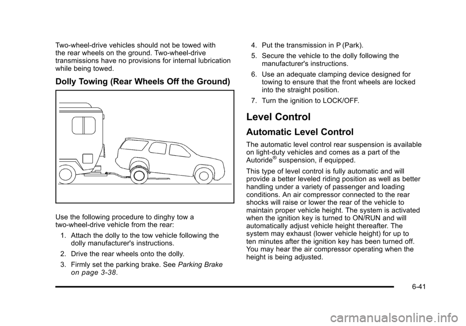
Dolly Towing (Rear Wheels Off the Ground)
Use the following procedure to dinghy tow atwo-wheel-drive vehicle from the rear:
1. Attach the dolly to the tow vehicle following thedolly manufacturer's instructions.
2. Drive the rear wheels onto the dolly.
3. Firmly set the parking brake. SeeParking Brakeon page 3!38.
4. Put the transmission in P (Park).
5. Secure the vehicle to the dolly following themanufacturer's instructions.
6. Use an adequate clamping device designed fortowing to ensure that the front wheels are lockedinto the straight position.
7. Turn the ignition to LOCK/OFF.
Level Control
Automatic Level Control
The automatic level control rear suspension is availableon light!duty vehicles and comes as a part of theAutoride®suspension, if equipped.
This type of level control is fully automatic and willprovide a better leveled riding position as well as betterhandling under a variety of passenger and loadingconditions. An air compressor connected to the rearshocks will raise or lower the rear of the vehicle tomaintain proper vehicle height. The system is activatedwhen the ignition key is turned to ON/RUN and willautomatically adjust vehicle height thereafter. Thesystem may exhaust (lower vehicle height) for up toten minutes after the ignition key has been turned off.You may hear the air compressor operating when theheight is being adjusted.
6-41
Page 444 of 616

Trailer Wiring Harness
Heavy-Duty Trailer Wiring Harness Package
The vehicle has a seven-pin universal heavy-duty trailerconnector attached to the rear bumper beam next to theintegrated trailer hitch.
The seven-wire harness contains the followingtrailer circuits:
.Yellow: Left Stop/Turn Signal
.Dark Green: Right Stop/Turn Signal
.Brown: Taillamps
.White: Ground
.Light Green: Back-up Lamps
.Red: Battery Feed*
.Dark Blue: Trailer Brake*
*The fuses for these two circuits are installed in theunderhood electrical center, but the wires are notconnected. They should be connected by yourdealer/retailer or a qualified service center.
If charging a remote (non-vehicle) battery, press thetow/haul mode button located at the end of the shiftlever. This will boost the vehicle system voltage andproperly charge the battery. If the trailer is too light fortow/haul mode, turn on the headlamps as a second wayto boost the vehicle system and charge the battery.
6-54
Page 445 of 616

Electric Brake Control Wiring
Provisions
These wiring provisions are included with the vehicle aspart of the trailer wiring package. These provisions arefor an electric brake controller. The instrument panelcontains blunt cut wires near the data link connector forthe trailer brake controller. The harness contains thefollowing wires:
.Dark Blue: Brake Signal to Trailer Connector
.Red/Black: Battery
.Light Blue/White: Brake Switch
.White: Ground
It should be installed by your dealer/retailer or aqualified service center.
Trailer Recommendations
Subtract the hitch loads from the Cargo Weight Rating(CWR). CWR is the maximum weight of the load thevehicle can carry. It does not include the weight of thepeople inside, but you can figure about 150 lbs. (68 kg)for each passenger. The total cargo load must not bemore than the vehicles CWR.
Weigh the vehicle with the trailer attached, so theGVWR or GAWR are not exceeded. If using aweight-distributing hitch, weigh the vehicle without thespring bars in place.
The best performance is obtained by correctlyspreading out the weight of the load and choosing thecorrect hitch and trailer brakes.
For more information seeTowing a Traileronpage 6!42.
6-55
Page 447 of 616

Section 7 Service and Appearance Care
Service. . . . . . . . . . . . . . . . . . . . . . . . . . . . . . . . . . . . . . . . . . . . . 7-4Accessories and Modifications . . . . . . . . . . . . . . . . . . 7-4California Proposition 65 Warning . . . . . . . . . . . . . . . 7-5California Perchlorate MaterialsRequirements . . . . . . . . . . . . . . . . . . . . . . . . . . . . . . . . . 7-5Doing Your Own Service Work . . . . . . . . . . . . . . . . . . 7-6Adding Equipment to the Outside of theVehicle . . . . . . . . . . . . . . . . . . . . . . . . . . . . . . . . . . . . . . . . 7-6
Fuel. . . . . . . . . . . . . . . . . . . . . . . . . . . . . . . . . . . . . . . . . . . . . . . . . 7-7Gasoline Octane . . . . . . . . . . . . . . . . . . . . . . . . . . . . . . . . 7-8Gasoline Specifications . . . . . . . . . . . . . . . . . . . . . . . . . 7-8California Fuel . . . . . . . . . . . . . . . . . . . . . . . . . . . . . . . . . . 7-8Additives . . . . . . . . . . . . . . . . . . . . . . . . . . . . . . . . . . . . . . . . 7-9Fuel E85 (85% Ethanol) . . . . . . . . . . . . . . . . . . . . . . . . . 7-9Fuels in Foreign Countries . . . . . . . . . . . . . . . . . . . . . 7-10Filling the Tank . . . . . . . . . . . . . . . . . . . . . . . . . . . . . . . . . 7-11Filling a Portable Fuel Container . . . . . . . . . . . . . . . 7-13
Checking Things Under the Hood. . . . . . . . . . . . . . . 7-14Hood Release . . . . . . . . . . . . . . . . . . . . . . . . . . . . . . . . . 7-15Engine Compartment Overview . . . . . . . . . . . . . . . . 7-16Engine Oil . . . . . . . . . . . . . . . . . . . . . . . . . . . . . . . . . . . . . 7-17Engine Oil Life System . . . . . . . . . . . . . . . . . . . . . . . . 7-20Engine Air Cleaner/Filter . . . . . . . . . . . . . . . . . . . . . . . 7-22
Automatic Transmission Fluid . . . . . . . . . . . . . . . . . . 7-24Cooling System . . . . . . . . . . . . . . . . . . . . . . . . . . . . . . . . 7-28Engine Coolant . . . . . . . . . . . . . . . . . . . . . . . . . . . . . . . . 7-29Engine Overheating . . . . . . . . . . . . . . . . . . . . . . . . . . . 7-34Overheated Engine ProtectionOperating Mode . . . . . . . . . . . . . . . . . . . . . . . . . . . . . 7-37Engine Fan Noise . . . . . . . . . . . . . . . . . . . . . . . . . . . . . 7-37Power Steering Fluid . . . . . . . . . . . . . . . . . . . . . . . . . . 7-38Windshield Washer Fluid . . . . . . . . . . . . . . . . . . . . . . 7-39Brakes . . . . . . . . . . . . . . . . . . . . . . . . . . . . . . . . . . . . . . . . . 7-40Battery . . . . . . . . . . . . . . . . . . . . . . . . . . . . . . . . . . . . . . . . . 7-43Jump Starting . . . . . . . . . . . . . . . . . . . . . . . . . . . . . . . . . . 7-44
All-Wheel Drive. . . . . . . . . . . . . . . . . . . . . . . . . . . . . . . . . . . 7-49
Rear Axle. . . . . . . . . . . . . . . . . . . . . . . . . . . . . . . . . . . . . . . . . 7-50
Front Axle. . . . . . . . . . . . . . . . . . . . . . . . . . . . . . . . . . . . . . . . . 7-51
Headlamp Aiming. . . . . . . . . . . . . . . . . . . . . . . . . . . . . . . . 7-52
Bulb Replacement. . . . . . . . . . . . . . . . . . . . . . . . . . . . . . . . 7-54High Intensity Discharge (HID) Lighting . . . . . . . . 7-54LED Lighting . . . . . . . . . . . . . . . . . . . . . . . . . . . . . . . . . . . 7-55Back-Up Lamps . . . . . . . . . . . . . . . . . . . . . . . . . . . . . . . 7-55License Plate Lamp . . . . . . . . . . . . . . . . . . . . . . . . . . . . 7-56Replacement Bulbs . . . . . . . . . . . . . . . . . . . . . . . . . . . . 7-56
7-1
Page 486 of 616

Brakes
Brake Fluid
The brake master cylinderreservoir is filled with DOT3 brake fluid. SeeEngineCompartment Overviewon page 7!16for thelocation of the reservoir.
There are only two reasons why the brake fluid level inthe reservoir might go down:
.The brake fluid level goes down because ofnormal brake lining wear. When new linings areinstalled, the fluid level goes back up.
.A fluid leak in the brake hydraulic system can alsocause a low fluid level. Have the brake hydraulicsystem fixed, since a leak means that sooner orlater the brakes will not work well.
Do not top off the brake fluid. Adding fluid does notcorrect a leak. If fluid is added when the linings areworn, there will be too much fluid when new brakelinings are installed. Add or remove brake fluid, asnecessary, only when work is done on the brakehydraulic system.
{WARNING:
If too much brake fluid is added, it can spill on the
engine and burn, if the engine is hot enough. You
or others could be burned, and the vehicle could
be damaged. Add brake fluid only when work is
done on the brake hydraulic system. See
“Checking Brake Fluid”in this section.
When the brake fluid falls to a low level, the brakewarning light comes on. SeeBrake System WarningLight on page 4!33.
Refer to the Maintenance Schedule to determine whento check the brake fluid. SeeScheduled Maintenanceo n p a g e 8!3.
7-40
Page 488 of 616

Brake Wear
This vehicle has disc brakes. Disc brake pads havebuilt-in wear indicators that make a high-pitchedwarning sound when the brake pads are worn and newpads are needed. The sound can come and go or beheard all the time the vehicle is moving, except whenapplying the brake pedal firmly.
{WARNING:
The brake wear warning sound means that soon
the brakes will not work well. That could lead to
an accident. When the brake wear warning sound
is heard, have the vehicle serviced.
Notice:Continuing to drive with worn-out brakepads could result in costly brake repair.
Some driving conditions or climates can cause a brakesqueal when the brakes are first applied or lightlyapplied. This does not mean something is wrong withthe brakes.
Properly torqued wheel nuts are necessary to helpprevent brake pulsation. When tires are rotated, inspectbrake pads for wear and evenly tighten wheel nuts inthe proper sequence to torque specifications inCapacities and Specifications on page 7!115.
Brake linings should always be replaced as completeaxle sets.
Brake Pedal Travel
See your dealer/retailer if the brake pedal does notreturn to normal height, or if there is a rapid increase inpedal travel. This could be a sign that brake servicemight be required.
Brake Adjustment
Every brake stop, the disc brakes adjust for wear.
7-42
Page 491 of 616

Notice:Ignoring these steps could result in costlydamage to the vehicle that would not be covered bythe warranty.
Trying to start the vehicle by pushing or pulling itwill not work, and it could damage the vehicle.
1. Check the other vehicle. It must have a 12-voltbattery with a negative ground system.
Notice:If the other vehicle's system is not a 12-voltsystem with a negative ground, both vehicles canbe damaged. Only use vehicles with 12-volt systemswith negative grounds to jump start your vehicle.
2. Get the vehicles close enough so the jumpercables can reach, but be sure the vehicles are nottouching each other. If they are, it could cause aground connection you do not want. You would notbe able to start your vehicle, and the badgrounding could damage the electrical systems.
To avoid the possibility of the vehicles rolling, setthe parking brake firmly on both vehicles involvedin the jump start procedure. Put the automatictransmission in P (Park) or a manual transmissionin Neutral before setting the parking brake. If youhave a four-wheel-drive vehicle, be sure thetransfer case is in a drive gear, not in Neutral.
Notice:If you leave the radio or other accessorieson during the jump starting procedure, they couldbe damaged. The repairs would not be covered bythe warranty. Always turn off the radio and otheraccessories when jump starting the vehicle.
3. Turn off the ignition on both vehicles. Unplugunnecessary accessories plugged into thecigarette lighter or the accessory power outlets.Turn off the radio and all the lamps that are notneeded. This avoids sparks and helps save bothbatteries. And it could save the radio!
4. Open the hood on the other vehicle and locate thepositive (+) and negative (!) terminal locations onthat vehicle.
Your vehicle has a remote positive (+) jump startingterminal and a remote negative (!) jump startingterminal. You should always use these remoteterminals instead of the terminals on the battery.
If the vehicle has a remote positive (+) terminal, itis located under a red plastic cover at the positivebattery post. To uncover the remote positive (+)terminal, open the red plastic cover.
7-45
Page 560 of 616

FusesUsage
52SEO B1 Upfitter Usage (Battery)
53Cigarette Lighter, Auxiliary PowerOutlet
54Automatic Level Control CompressorRelay
55Climate Controls (Ignition)
56Engine Control Module, SecondaryFuel Pump (Ignition)
J-Case FusesUsage
57Cooling Fan 1
58Automatic Level Control Compressor
59Heavy Duty Antilock Braking System
60Cooling Fan 2
61Antilock Brake System 1
62Starter
63Stud 2 (Trailer Brakes)
64Left Bussed Electrical Center 1
65Electric Running Boards
66Heated Windshield Washer System
67Transfer Case
J-Case FusesUsage
68Stud 1 (Trailer Connector BatteryPower)
69Mid-Bussed Electrical Center 1
70Climate Control Blower
71Power Liftgate Module
72Left Bussed Electrical Center 2
RelaysUsage
FAN HICooling Fan High Speed
FAN LOCooling Fan Low Speed
FAN CNTRL Cooling Fan Control
HDLP LO/HID Low-Beam Headlamp
FOG LAMPFront Fog Lamps
A/C CMPRSR Air Conditioning Compressor
STRTRStarter
PWR/TRNPowertrain
FUEL PMPFuel Pump
PRK LAMPParking Lamps
REAR DEFOG Rear Defogger
RUN/CRANK Switched Power
7-114