Page 17 of 150
2-3
12
3
4
5
6
7
8
9
10
11
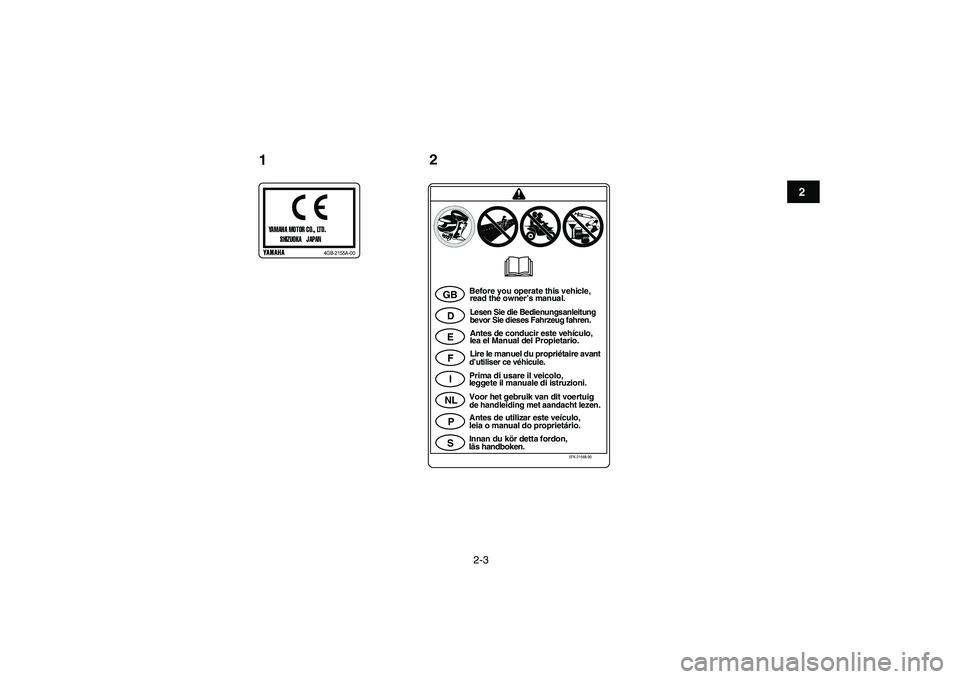
YAMAHA MOTOR CO., LTD.
SHIZUOKA JAPANp
4GB-2155A-00
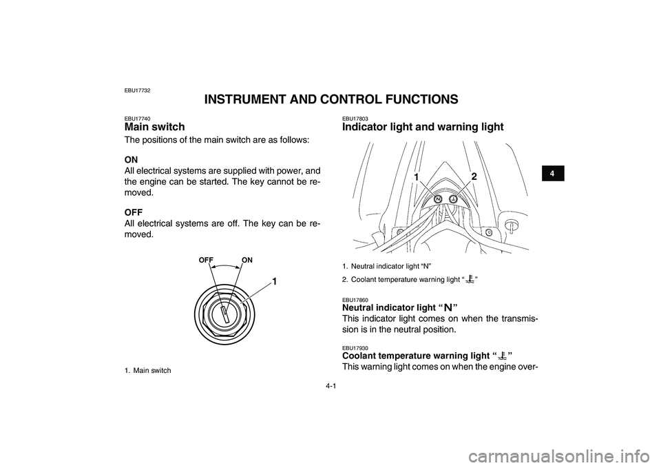
GB
D
E
F
I
NL
P
S
Before you operate this vehicle,
read the owner’s manual.Lesen Sie die Bedienungsanleitung
bevor Sie dieses Fahrzeug fahren.Antes de conducir este vehículo,
lea el Manual del Propietario.
Lire le manuel du propriétaire avantd’utiliser ce véhicule.Prima di usare il veicolo,
leggete il manuale di istruzioni.
Voor het gebruik van dit voertuigde handleiding met aandacht lezen.Antes de utilizar este veículo,
leia o manual do proprietário.
Innan du kör detta fordon,läs handboken.
5FK-21568-00
12
Page 18 of 150
2-4
12
3
4
5
6
7
8
9
10
11
3Use PREMIUM unleaded gasoline with min. 97 octane(RON).
Nur Super Bleifrei mit Mindestoktanzahl 97 (ROZ) tanken.
Utilice gasolina sin plomo que tenga como mínimo 97 octanos (RON).
Utiliser une essence SUPER sans plomb d’un indice
d’octane (RON) de min. 97.
Utilizzare benzina PREMIUM super senza piombo con almeno 97
ottani (RON).
Gebruik loodvrije SUPERBENZINE met een octaangetal (RON) van
minstens 97.Utilize gasolina sem chumbo com índice de octano mínimo de 97 (RON).Använd blyfri PREMIUMBENSIN av 97 oktan (RON) eller mer.
5TG-2415E-00
<
16
5FK-21697-00
4
5FK-2151H-00
5TG-21696-40
27.5 kPa0.275 kgf/cm
2
4.0 psi
30 kPa
0.30 kgf/cm
2
4.4 psi
GBDEF
INLPS
Set with tires cold.
Pneus à froid. Bei kalten Reifen.
Ajuste con los
neumáticos an frío.Impostare a pneumatici
freddi.
Ställ in med kalla däck. Wanneer de banden
koud zijn.
Regular com pneus
frios.
5
67
Page 19 of 150
3-1
1
23
4
5
6
7
8
9
10
11
EBU17680
DESCRIPTION
EBU17690
Left view
EBU17700
Right view
1. Headlights
2. Fuel cock
3. Starter (choke)
4. Throttle stop screw
5. Fuse
6. Tail/brake light
7. Coolant reservoir
8. Shift pedal
9. Engine oil tank
1
23456
7
8
9
1. Spark arrester
2. Seat
3. Fuel tank cap
4. Radiator cap
5. Oil filter element
6. Brake pedal
1
2
3
4
5 6
Page 20 of 150
3-2
1
23
4
5
6
7
8
9
10
11
EBU17712
Controls and instruments
TIP
The ATV you have purchased may differ slightly
from the figures shown in this manual.
1. Clutch lever
2. Handlebar switches
3. Parking brake
4. Main switch
5. Throttle lever
6. Brake lever
2
123456
Page 21 of 150
4-1
1
2
34
5
6
7
8
9
10
11
EBU17732
INSTRUMENT AND CONTROL FUNCTIONS
EBU17740
Main switch
The positions of the main switch are as follows:
ON
All electrical systems are supplied with power, and
the engine can be started. The key cannot be re-
moved.
OFF
All electrical systems are off. The key can be re-
moved.
EBU17803
Indicator light and warning light
EBU17860
Neutral indicator light “”
This indicator light comes on when the transmis-
sion is in the neutral position.
EBU17930
Coolant temperature warning light “”
This warning light comes on when the engine over-
1. Main switch
OFF ON
1
1. Neutral indicator light “N”
2. Coolant temperature warning light “”
12
Page 22 of 150

4-2
1
2
34
5
6
7
8
9
10
11
heats. When this occurs during operation, stop the
engine as soon as it is safe to do so and allow it to
cool down for about 10 minutes.
The electrical circuit of the warning light can be
checked according to the following procedure.
1. Set the engine stop switch to “” and turn the
key to “ON”.
2. Shift the transmission into the neutral position
or pull the clutch lever.
3. Push the start switch. If the warning light does
not come on while the start switch is pushed,
have a Yamaha dealer check the electrical cir-
cuit.
NOTICE
ECB00010
The engine may overheat if the ATV is over-
loaded. In this case, reduce the load to spec-
ification.
Start the engine after making sure that the
warning light is out. Continuous use while
the warning light is on may cause damage to
the engine.
EBU18061
Handlebar switches
EBU18080
Engine stop switch “/”
Set this switch to “” before starting the engine.
The engine stop switch controls the ignition and
stops the engine when it is running. Use this switch
to stop the engine in an emergency situation. The
engine will not start or run when this switch is set
to “”.
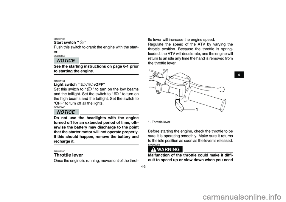
1. Light switch “/ /OFF”
2. Engine stop switch “/”
3. Start switch “”
1
2
3
Page 23 of 150

4-3
1
2
34
5
6
7
8
9
10
11
EBU18100
Start switch “”
Push this switch to crank the engine with the start-
er.
NOTICE
ECB00050
See the starting instructions on page 6-1 prior
to starting the engine.
EBU18151
Light switch “/ /OFF”
Set this switch to “” to turn on the low beams
and the taillight. Set the switch to “” to turn on
the high beams and the taillight. Set the switch to
“OFF” to turn off all the lights.
NOTICE
ECB00040
Do not use the headlights with the engine
turned off for an extended period of time, oth-
erwise the battery may discharge to the point
that the starter motor will not operate properly.
If this should happen, remove the battery and
recharge it.
EBU18280
Throttle lever
Once the engine is running, movement of the throt-tle lever will increase the engine speed.
Regulate the speed of the ATV by varying the
throttle position. Because the throttle is spring-
loaded, the ATV will decelerate, and the engine will
return to an idle any time the hand is removed from
the throttle lever.
Before starting the engine, check the throttle to be
sure it is operating smoothly. Make sure it returns
to the idle position as soon as the lever is released.
WARNING
EWB00250
Malfunction of the throttle could make it diffi-
cult to speed up or slow down when you need
1. Throttle lever
Page 24 of 150

4-4
1
2
34
5
6
7
8
9
10
11
to. This could cause an accident. Check the op-
eration of the throttle lever before you start the
engine. If the throttle does not work smoothly,
check for the cause. Correct the problem be-
fore riding the ATV or consult a Yamaha dealer.
EBU18321
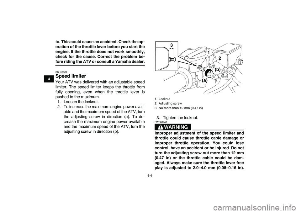
Speed limiter
Your ATV was delivered with an adjustable speed
limiter. The speed limiter keeps the throttle from
fully opening, even when the throttle lever is
pushed to the maximum.
1. Loosen the locknut.
2. To increase the maximum engine power avail-
able and the maximum speed of the ATV, turn
the adjusting screw in direction (a). To de-
crease the maximum engine power available
and the maximum speed of the ATV, turn the
adjusting screw in direction (b).3. Tighten the locknut.WARNING
EWB00240
Improper adjustment of the speed limiter and
throttle could cause throttle cable damage or
improper throttle operation. You could lose
control, have an accident or be injured. Do not
turn the adjusting screw out more than 12 mm
(0.47 in) or the throttle cable could be dam-
aged. Always make sure the throttle lever free
play is adjusted to 2.0–4.0 mm (0.08–0.16 in).
1. Locknut
2. Adjusting screw
3. No more than 12 mm (0.47 in)3
1
2
(a)
(b)