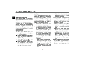
Page 25 of 82

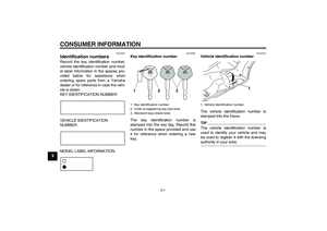
INSTRUMENT AND CONTROL FUNCTIONS
3-10
3
EAUM2161
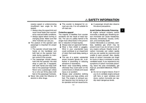
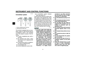
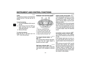
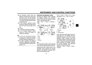
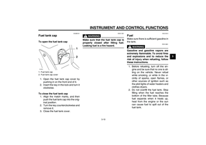
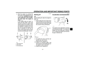
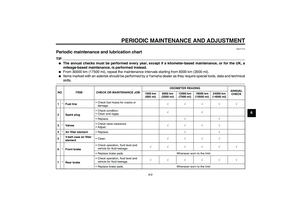
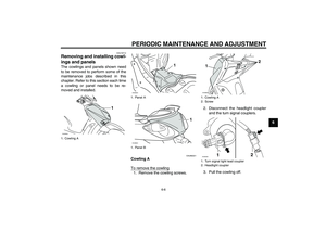
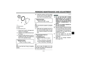
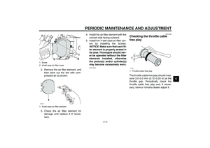
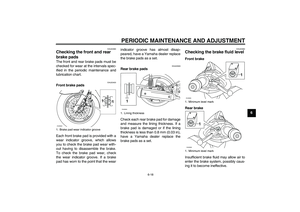
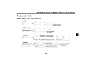
Fuel tank cap To open the fuel tank cap
1. Open the fuel tank cap cover by
pushing in on the front end of it.
2. Insert the key in the lock and turn it
clockwise.
To close the fuel tank cap
1. Align the match marks, and then
push the fuel tank cap into the orig-
inal position.
2. Turn the key counterclockwise and
remove it.
3. Close the fuel tank cover.
WARNING
EWA11091
Make sure that the fuel tank cap is
properly closed after filling fuel.Leaking fuel is a fire hazard.
EAU13212
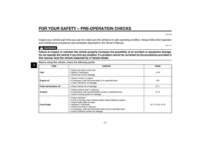
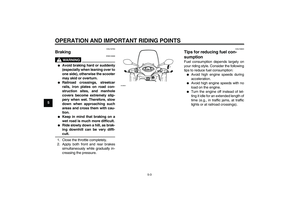
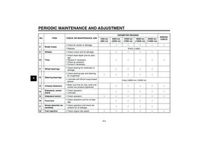
Fuel Make sure there is sufficient gasoline in
the tank.
WARNING
EWA10881
Gasoline and gasoline vapors are
extremely flammable. To avoid fires
and explosions and to reduce the
risk of injury when refueling, followthese instructions.
1. Before refueling, turn off the en-
gine and be sure that no one is sit-
ting on the vehicle. Never refuel
while smoking, or while in the vi-
cinity of sparks, open flames, or
other sources of ignition such as
the pilot lights of water heaters and
clothes dryers.
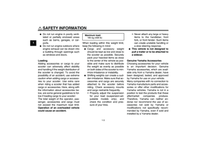
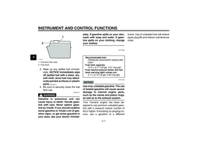
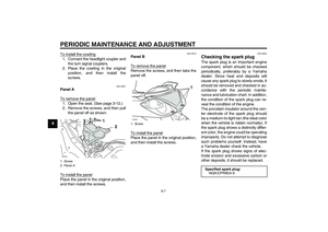
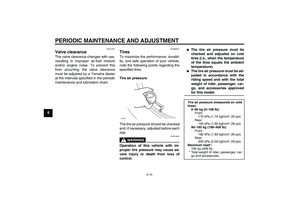
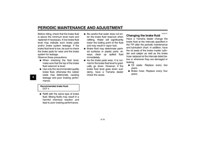
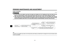
2. Do not overfill the fuel tank. Stop
filling when the fuel reaches the
bottom of the filler tube. Because
fuel expands when it heats up,
heat from the engine or the sun
can cause fuel to spill out of the
fuel tank.
1. Fuel tank cap
2. Fuel tank cap coverZAUM0643
1
2
U16PE1E0.book Page 10 Monday, July 28, 2008 9:57 AM
Page 26 of 82

INSTRUMENT AND CONTROL FUNCTIONS
3-11
3
3. Wipe up any spilled fuel immedi-
ately. NOTICE: Immediately wipe
off spilled fuel with a clean, dry,
soft cloth, since fuel may deteri-
orate painted surfaces or plastic
parts.
[ECA10071]
4. Be sure to securely close the fuel
tank cap.
WARNING
EWA15151
Gasoline is poisonous and can
cause injury or death. Handle gaso-
line with care. Never siphon gaso-
line by mouth. If you should swallow
some gasoline or inhale a lot of gas-
oline vapor, or get some gasoline in
your eyes, see your doctor immedi-ately. If gasoline spills on your skin,
wash with soap and water. If gaso-
line spills on your clothing, change
your clothes.
EAU13390
NOTICE
ECA11400
Use only unleaded gasoline. The use
of leaded gasoline will cause severe
damage to internal engine parts,
such as the valves and piston rings,as well as to the exhaust system.
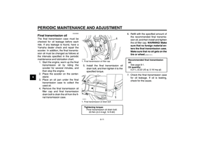
Your Yamaha engine has been de-
signed to use premium unleaded gaso-
line with a research octane number of
95 or higher. If knocking (or pinging) oc-
curs, use a gasoline of a differentbrand. Use of unleaded fuel will extend
spark plug life and reduce maintenance
costs.
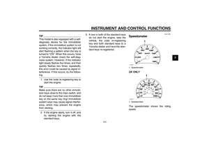
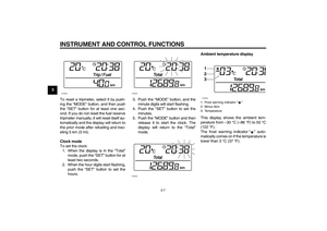
1. Fuel tank filler tube
2. Fuel level
1
2
ZAUM0020
Recommended fuel:
PREMIUM UNLEADED GASOLINE
ONLY
Fuel tank capacity:
10.5 L (2.77 US gal, 2.31 Imp.gal)
Fuel reserve amount (when the fuel
level warning light comes on):
2.7 L (0.72 US gal, 0.60 Imp.gal)
U16PE1E0.book Page 11 Monday, July 28, 2008 9:57 AM
Page 27 of 82

INSTRUMENT AND CONTROL FUNCTIONS
3-12
3
EAU13445
Catalytic converters This vehicle is equipped with catalytic
converters in the exhaust system.
WARNING
EWA10862
The exhaust system is hot after op-
eration. To prevent a fire hazard or
burns:�
Do not park the vehicle near
possible fire hazards such as
grass or other materials that
easily burn.
�
Park the vehicle in a place
where pedestrians or children
are not likely to touch the hot
exhaust system.
�
Make sure that the exhaust sys-
tem has cooled down before do-
ing any maintenance work.
�
Do not allow the engine to idle
more than a few minutes. Long
idling can cause a build-up ofheat.
NOTICE
ECA10701
Use only unleaded gasoline. The use
of leaded gasoline will cause unre-
pairable damage to the catalyticconverter.
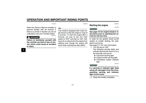
EAU13932
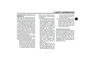
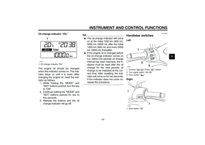
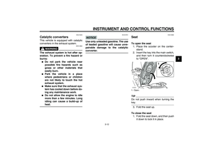
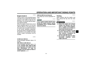
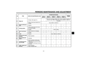
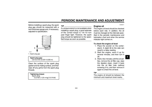
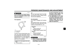
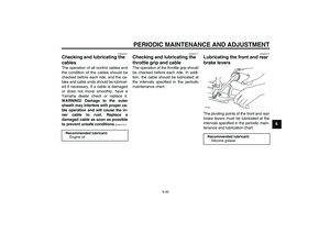
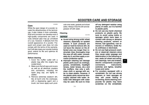
Seat To open the seat
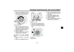
1. Place the scooter on the center-
stand.
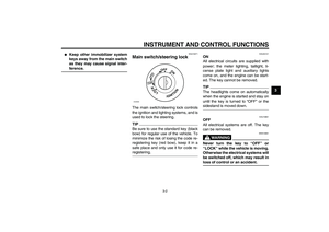
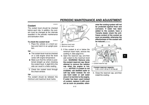
2. Insert the key into the main switch,
and then turn it counterclockwise
to “OPEN”.TIPDo not push inward when turning thekey.
3. Fold the seat up.
To close the seat
1. Fold the seat down, and then push
it down to lock it in place.1. Open.ZAUM0698
1
PUSHOPEN
OFFON
LOCK
IGNITION
U16PE1E0.book Page 12 Monday, July 28, 2008 9:57 AM
Page 28 of 82

INSTRUMENT AND CONTROL FUNCTIONS
3-13
32. Remove the key from the main
switch if the scooter will be left un-
attended.
TIPMake sure that the seat is properly se-cured before riding.
EAUM2521
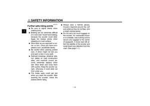
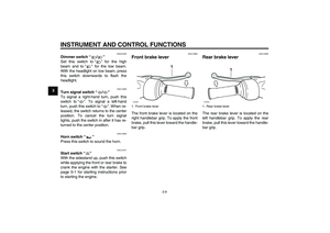
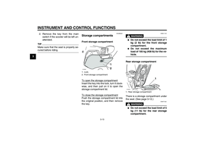
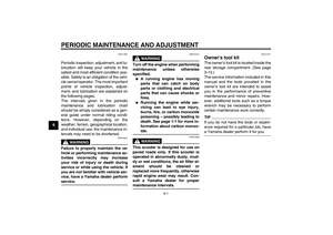
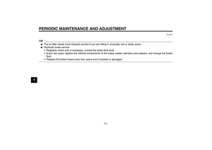
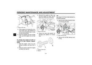
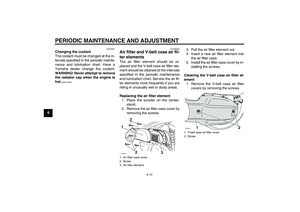
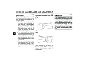
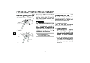
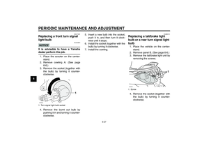
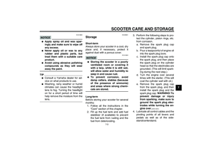
Storage compartments Front storage compartment
To open the storage compartmentInsert the key into the lock, turn it clock-
wise, and then pull on it to open the
storage compartment lid.
To close the storage compartmentPush the storage compartment lid into
the original position, and then remove
the key.
WARNING
EWA11191
�
Do not exceed the load limit of 1
kg (2 lb) for the front storage
compartment.
�
Do not exceed the maximum
load of 185 kg (408 lb) for the ve-hicle.
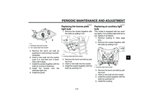
Rear storage compartment
There is a storage compartment under
the seat. (See page 3-12.)WARNING
EWAT1051
�
Do not exceed the load limit of 5
kg (11 lb) for the rear storage
compartment.
1. Lock.
2. Front storage compartment
1
2
ZAUM0699
1. Rear storage compartmentZAUM0646
1
U16PE1E0.book Page 13 Monday, July 28, 2008 9:57 AM
Page 29 of 82
 for the ve-hicle.
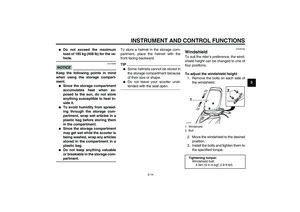
NOTICE
ECA10080
Keep the following points in mind
when using the storage compart-
ment.�
S")
INSTRUMENT AND CONTROL FUNCTIONS
3-14
3
�
Do not exceed the maximum
load of 185 kg (408 lb) for the ve-hicle.
NOTICE
ECA10080
Keep the following points in mind
when using the storage compart-
ment.�
Since the storage compartment
accumulates heat when ex-
posed to the sun, do not store
anything susceptible to heat in-
side it.
�
To avoid humidity from spread-
ing through the storage com-
partment, wrap wet articles in a
plastic bag before storing them
in the compartment.
�
Since the storage compartment
may get wet while the scooter is
being washed, wrap any articles
stored in the compartment in a
plastic bag.
�
Do not keep anything valuable
or breakable in the storage com-partment.To store a helmet in the storage com-
partment, place the helmet with the
front facing backward.
TIP�
Some helmets cannot be stored in
the storage compartment because
of their size or shape.
�
Do not leave your scooter unat-tended with the seat open.
EAUM2490
Windshield To suit the rider’s preference, the wind-
shield height can be changed to one of
four positions.
To adjust the windshield height
1. Remove the bolts on each side of
the windshield.
2. Move the windshield to the desired
position.
3. Install the bolts and tighten them to
the specified torque.1. Windshield
2. Bolt
Tightening torque:
Windshield bolt:
4 Nm (0.4 m·kgf, 2.9 ft·lbf)ZAUM0797
1
2
U16PE1E0.book Page 14 Monday, July 28, 2008 9:57 AM
Page 30 of 82

INSTRUMENT AND CONTROL FUNCTIONS
3-15
3
WARNING
EWA10920
After adjusting the windshield:�
Securely tighten the windshield
bolts.
�
Turn the handlebar to the left
and right to make sure that the
handlebar is not obstructed and
that the windshield does not
contact any other parts.
�
Open the throttle and make sure
that the throttle grip returns
properly when released, other-
wise an accident or injury couldresult.
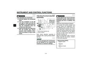
EAU14881
Adjusting the shock absorber
assemblies Each shock absorber assembly is
equipped with a spring preload adjust-
ing ring.NOTICE
ECA10101
To avoid damaging the mechanism,
do not attempt to turn beyond themaximum or minimum settings.
WARNING
EWA10210
Always adjust both shock absorber
assemblies equally, otherwise poor
handling and loss of stability mayresult.
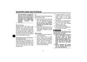
Adjust the spring preload as follows.
To increase the spring preload and
thereby harden the suspension, turn
the adjusting ring on each shock ab-
sorber assembly in direction (a). To de-
crease the spring preload and thereby
soften the suspension, turn the adjust-
ing ring on each shock absorber as-
sembly in direction (b).
Align the appropriate notch in the ad-
justing ring with the position indicator
on the shock absorber.
1. Spring preload adjusting ring
2. Position indicator
1
2
3
4
1
2
(b)
(a)
ZAUM0414
Spring preload setting:
Minimum (soft):
1
Standard:
2
Maximum (hard):
4
U16PE1E0.book Page 15 Monday, July 28, 2008 9:57 AM
Page 31 of 82
 for the carrier.
�
Do not exceed the maximum
load of 185 kg (408 lb) for the v")
INSTRUMENT AND CONTROL FUNCTIONS
3-16
3
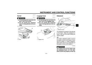
EAU15112
Carrier
WARNING
EWA10171
�
Do not exceed the load limit of 5
kg (11 lb) for the carrier.
�
Do not exceed the maximum
load of 185 kg (408 lb) for the ve-hicle.
EAUT1072
Luggage hook
WARNING
EWAT1031
�
Do not exceed the load limit of 3
kg (7 lb) for the luggage hook.
�
Do not exceed the maximum
load of 185 kg (408 lb) for the ve-hicle.
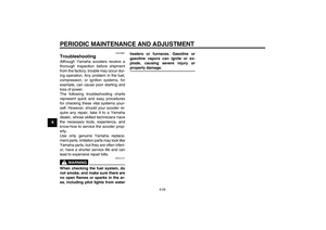
EAU15301
Sidestand The sidestand is located on the left side
of the frame. Raise the sidestand or
lower it with your foot while holding the
vehicle upright.TIPThe built-in sidestand switch is part of
the ignition circuit cut-off system, which
cuts the ignition in certain situations.
(See further down for an explanation ofthe ignition circuit cut-off system.)
WARNING
EWA10240
The vehicle must not be ridden with
the sidestand down, or if the side-
stand cannot be properly moved up
1. CarrierZAUM0798
1
1. Luggage hookZAUM0700
1
1. Sidestand switchZAUM0648
1
U16PE1E0.book Page 16 Monday, July 28, 2008 9:57 AM
Page 32 of 82
, otherwise the
sidestand could contact the ground
and distract the operator, resulting
in a possible loss of control.
Yamaha’s ignition c")
INSTRUMENT AND CONTROL FUNCTIONS
3-17
3(or does not stay up), otherwise the
sidestand could contact the ground
and distract the operator, resulting
in a possible loss of control.
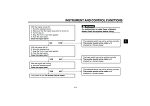
Yamaha’s ignition circuit cut-off
system has been designed to assist
the operator in fulfilling the respon-
sibility of raising the sidestand be-
fore starting off. Therefore, check
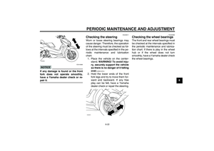
this system regularly as described
below and have a Yamaha dealer re-
pair it if it does not function proper-
ly.
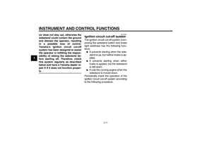
EAU45051
Ignition circuit cut-off system The ignition circuit cut-off system (com-
prising the sidestand switch and brake
light switches) has the following func-
tions.�
It prevents starting when the side-
stand is up, but neither brake is ap-
plied.
�
It prevents starting when either
brake is applied, but the sidestand
is still down.
�
It cuts the running engine when the
sidestand is moved down.
Periodically check the operation of the
ignition circuit cut-off system according
to the following procedure.
U16PE1E0.book Page 17 Monday, July 28, 2008 9:57 AM