Page 17 of 82

INSTRUMENT AND CONTROL FUNCTIONS
3-2
3
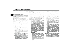
�
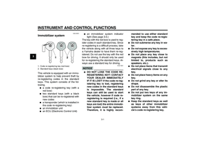
Keep other immobilizer system
keys away from the main switch
as they may cause signal inter-ference.
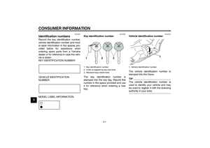
EAU10471
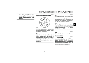
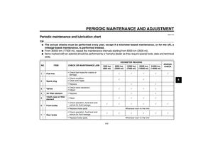
Main switch/steering lock The main switch/steering lock controls
the ignition and lighting systems, and is
used to lock the steering.TIPBe sure to use the standard key (black
bow) for regular use of the vehicle. To
minimize the risk of losing the code re-
registering key (red bow), keep it in a
safe place and only use it for code re-registering.
EAU34121
ON
All electrical circuits are supplied with
power; the meter lighting, taillight, li-
cense plate light and auxiliary lights
come on, and the engine can be start-
ed. The key cannot be removed.TIPThe headlights come on automatically
when the engine is started and stay on
until the key is turned to “OFF” or thesidestand is moved down.
EAU10661
OFF
All electrical systems are off. The key
can be removed.
WARNING
EWA10061
Never turn the key to “OFF” or
“LOCK” while the vehicle is moving.
Otherwise the electrical systems will
be switched off, which may result inloss of control or an accident.
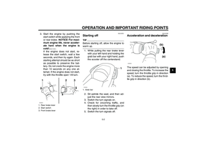
PUSHOPEN
OFF
ON
LOCK
IGNITION
ZAUM0696
U16PE1E0.book Page 2 Monday, July 28, 2008 9:57 AM
Page 18 of 82

INSTRUMENT AND CONTROL FUNCTIONS
3-3
3
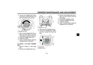
EAU10681
LOCK
The steering is locked, and all electrical
systems are off. The key can be re-
moved.
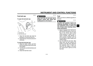
To lock the steering1. Turn the handlebars all the way to
the left.
2. Push the key in from the “OFF” po-
sition, and then turn it to “LOCK”
while still pushing it.
3. Remove the key.
To unlock the steeringPush the key in, and then turn it to
“OFF” while still pushing it.
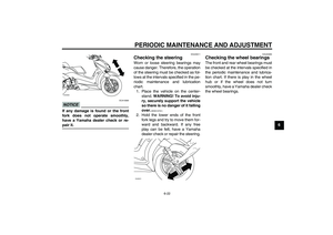
EAU11003
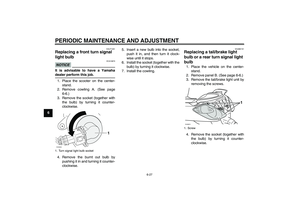
Indicator and warning lights
EAU11030
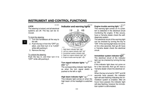
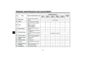
Turn signal indicator lights“”
and“”
The corresponding indicator light flash-
es when the turn signal switch is
pushed to the left or right.
EAU11080
High beam indicator light“”
This indicator light comes on when the
high beam of the headlight is switched
on.
EAU11482
Engine trouble warning light“”
This warning light comes on if a prob-
lem is detected in the electrical circuit
monitoring the engine. If this occurs,
have a Yamaha dealer check the self-
diagnosis system.
The electrical circuit of the warning light
can be checked by turning the key to
“ON”. If the warning light does not come
on for a few seconds, then go off, have
a Yamaha dealer check the electrical
circuit.
EAU38911
Immobilizer system indicator light
The electrical circuit of the indicator
light can be checked by turning the key
to “ON”.
If the indicator light does not come on
for a few seconds, then go off, have a
Yamaha dealer check the electrical cir-
cuit.
When the key is turned to “OFF” and 30
seconds have passed, the indicator
light will start flashing indicating the im-
mobilizer system is enabled. After 24
hours have passed, the indicator light
will stop flashing, however the immobi-
lizer system is still enabled.
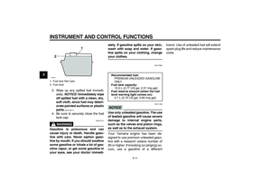
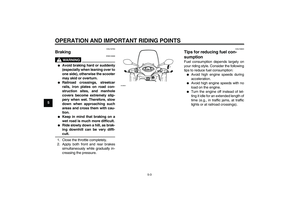
1. High beam indicator light“”
2. Left turn signal indicator light“”
3. Immobilizer system indicator light
4. Right turn signal indicator light“”
5. Engine trouble warning light“”
12 3 4 5
ZAUM0697
U16PE1E0.book Page 3 Monday, July 28, 2008 9:57 AM
Page 19 of 82

INSTRUMENT AND CONTROL FUNCTIONS
3-4
3
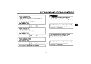
TIPThis model is also equipped with a self-
diagnosis device for the immobilizer
system. If the immobilizer system is not
working correctly, the indicator light will
start flashing a pattern when the key is
turned to “ON”. When this occurs, have
a Yamaha dealer check the self-diag-
nosis system. However, if the indicator
light slowly flashes five times, and then
quickly flashes two times repeatedly,
this error could be caused by signal in-
terference. If this occurs, try the follow-ing.
1. Use the code re-registering key to
start the engine.TIPMake sure there are no other immobi-
lizer keys close to the main switch, and
do not keep more than one immobilizer
key on the same key ring! Immobilizer
system keys may cause signal interfer-
ence, which may prevent the enginefrom starting.
2. If the engine starts, turn it off, and
try starting the engine with the
standard keys.3. If one or both of the standard keys
do not start the engine, take the
vehicle, the code re-registering
key and both standard keys to a
Yamaha dealer and have the stan-
dard keys re-registered.
EAU11591
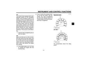
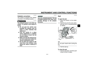
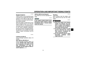
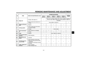
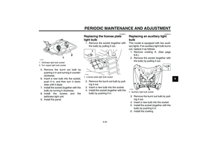
Speedometer UK ONLY
The speedometer shows the riding
speed.1. Speedometer
1. Speedometer
1
ZAUM0636
1mph
0 1020304050
60
70
80
90
100
ZAUM0637
U16PE1E0.book Page 4 Monday, July 28, 2008 9:57 AM
Page 20 of 82
 as the fuel level
decreases. When the")
INSTRUMENT AND CONTROL FUNCTIONS
3-5
3
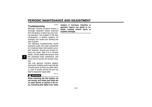
EAUM1471
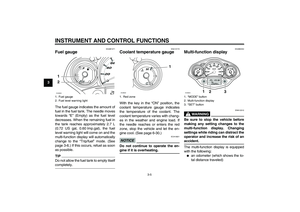
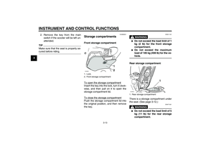
Fuel gauge The fuel gauge indicates the amount of
fuel in the fuel tank. The needle moves
towards “E” (Empty) as the fuel level
decreases. When the remaining fuel in
the tank reaches approximately 2.7 L
(0.72 US gal, 0.60 Imp.gal), the fuel
level warning light will come on and the
multi-function display will automatically
change to the “Trip/fuel” mode. (See
page 3-6.) If this occurs, refuel as soon
as possible.TIPDo not allow the fuel tank to empty itselfcompletely.
EAU12172
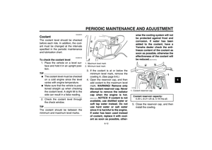
Coolant temperature gauge With the key in the “ON” position, the
coolant temperature gauge indicates
the temperature of the coolant. The
coolant temperature varies with chang-
es in the weather and engine load. If
the needle reaches or enters the red
zone, stop the vehicle and let the en-
gine cool. (See page 6-30.)NOTICE
ECA10021
Do not continue to operate the en-gine if it is overheating.
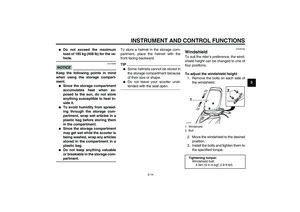
EAUM2252
Multi-function display
WARNING
EWA12312
Be sure to stop the vehicle before
making any setting changes to the
multi-function display. Changing
settings while riding can distract the
operator and increase the risk of anaccident.
The multi-function display is equipped
with the following:�
an odometer (which shows the to-
tal distance traveled)
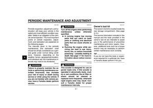
1. Fuel gauge
2. Fuel level warning light1
2ZAUM0638
1. Red zone
1
ZAUM0639
1.“MODE” button
2. Multi-function display
3.“SET” button
1
2
3
ZAUM0640
U16PE1E0.book Page 5 Monday, July 28, 2008 9:57 AM
Page 21 of 82

INSTRUMENT AND CONTROL FUNCTIONS
3-6
3
�
two tripmeters (which show the
distance traveled since they were
last set to zero, the time passed
since the tripmeters were set to ze-
ro, and the average speed traveled
during this time)
�
a fuel reserve tripmeter (which
shows the distance traveled since
the fuel level warning light came
on)
�
a clock
�
an ambient temperature display
�
an oil change indicator (which
comes on when the engine oil
should be changed)
TIP�
For the UK, the distance traveled
is displayed in miles and the tem-
perature reading is displayed in °F.
�
For other countries, the distance
traveled is displayed in kilometers
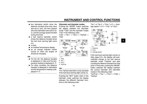
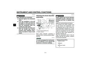
and the temperature reading is dis-played in °C.Odometer and tripmeter modes
Pushing the “MODE” button switches
the display between the odometer
mode “Total” and the tripmeter modes
“Trip” in the following order:
Total → Trip 1 → Trip 2 → Trip/fuel →
Total
TIPThe Trip/fuel odometer is only activatedif the fuel level warning light comes on.
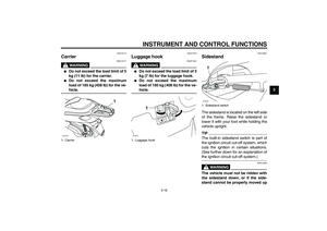
Pushing the “SET” button when in the
tripmeter mode switches the display
between the different tripmeter func-
tions in the following order:Trip 1 or Trip 2 → Time 1 or 2 → Aver-
age speed 1 or 2 → Trip 1 or Trip 2
If the fuel level warning light comes on
(See page 3-5.), the display will auto-
matically change to the fuel reserve
tripmeter mode “Trip/fuel” and start
counting the distance traveled from that
point. In that case, pushing the “MODE”
button switches the display between
the various tripmeter and odometer
modes in the following order:
Trip/Fuel → Trip 1 → Trip 2 → Total →
Trip/fuel1. Total
2. Trip 1
3. Trip 2
4. Trip/Fuel
"Mode"
"Mode"
"Mode"
"Mode"1
2
3
4
ZAUM0391
1. Distance
2. Time
3. Average speed
"Set"
"Set""Set"
12
3
ZAUM0392
U16PE1E0.book Page 6 Monday, July 28, 2008 9:57 AM
Page 22 of 82

INSTRUMENT AND CONTROL FUNCTIONS
3-7
3
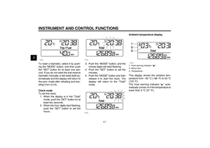
To reset a tripmeter, select it by push-
ing the “MODE” button, and then push
the “SET” button for at least one sec-
ond. If you do not reset the fuel reserve
tripmeter manually, it will reset itself au-
tomatically and the display will return to
the prior mode after refueling and trav-
eling 5 km (3 mi).
Clock mode
To set the clock:
1. When the display is in the “Total”
mode, push the “SET” button for at
least two seconds.
2. When the hour digits start flashing,
push the “SET” button to set the
hours.3. Push the “MODE” button, and the
minute digits will start flashing.
4. Push the “SET” button to set the
minutes.
5. Push the “MODE” button and then
release it to start the clock. The
display will return to the “Total”
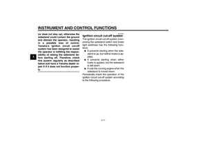
mode.Ambient temperature display
This display shows the ambient tem-
perature from –30 °C (–86 °F) to 50 °C
(122 °F).
The frost warning indicator“” auto-
matically comes on if the temperature is
lower than 3 °C (37 °F).
ZAUM0393
ZAUM0394ZAUM0395
1. Frost warning indicator“”
2. Minus item
3. Temperature1
2
3ZAUM0396
U16PE1E0.book Page 7 Monday, July 28, 2008 9:57 AM
Page 23 of 82

INSTRUMENT AND CONTROL FUNCTIONS
3-8
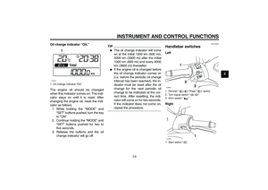
3 Oil change indicator “OIL”
The engine oil should be changed
when this indicator comes on. The indi-
cator stays on until it is reset. After
changing the engine oil, reset the indi-
cator as follows.
1. While holding the “MODE” and
“SET” buttons pushed, turn the key
to“ON”.
2. Continue holding the “MODE” and
“SET” buttons pushed for two to
five seconds.
3. Release the buttons and the oil
change indicator will go off.
TIP�
The oil change indicator will come
on at the initial 1000 km (600 mi),
5000 km (3000 mi) after the initial
1000 km (600 mi) and every 6000
km (3600 mi) thereafter.
�
If the engine oil is changed before
the oil change indicator comes on
(i.e. before the periodic oil change
interval has been reached), the in-
dicator must be reset after the oil
change for the next periodic oil
change to be indicated at the cor-
rect time. After resetting, the indi-
cator will come on for two seconds.
If the indicator does not come on,repeat the procedure.
EAU12347
Handlebar switches Left
Right
1. Oil change indicator “OIL”
1
ZAUM0582
1. Dimmer“/”/Pass“” switch
2. Turn signal switch“/”
3. Horn switch“”
1. Start switch“”ZAUM0642
1
U16PE1E0.book Page 8 Monday, July 28, 2008 9:57 AM
Page 24 of 82

INSTRUMENT AND CONTROL FUNCTIONS
3-9
3
EAUS1020
Dimmer switch“/”
Set this switch to“” for the high
beam and to“” for the low beam.
With the headlight on low beam, press
this switch downwards to flash the
headlight.
EAU12460
Turn signal switch“/”
To signal a right-hand turn, push this
switch to“”. To signal a left-hand
turn, push this switch to“”. When re-
leased, the switch returns to the center
position. To cancel the turn signal
lights, push the switch in after it has re-
turned to the center position.
EAU12500
Horn switch“”
Press this switch to sound the horn.
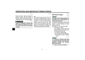
EAU12721
Start switch“”
With the sidestand up, push this switch
while applying the front or rear brake to
crank the engine with the starter. See
page 5-1 for starting instructions prior
to starting the engine.
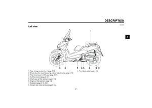
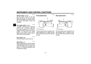
EAU12900
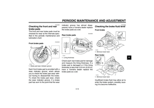
Front brake lever The front brake lever is located on the
right handlebar grip. To apply the front
brake, pull this lever toward the handle-
bar grip.
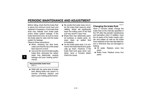
EAU12950
Rear brake lever The rear brake lever is located on the
left handlebar grip. To apply the rear
brake, pull this lever toward the handle-
bar grip.
1. Front brake lever
1
ZAUM0084
1. Rear brake lever
1
ZAUM0085
U16PE1E0.book Page 9 Monday, July 28, 2008 9:57 AM