Page 57 of 80

PERIODIC MAINTENANCE AND ADJUSTMENT
6-27
6
EAU47760
Replacing a headlight bulb If a headlight bulb burns out, replace it
as follows.NOTICE
ECA10650
Take care not to damage the follow-
ing parts:�
Headlight bulb
Do not touch the glass part of
the headlight bulb to keep it free
from oil, otherwise the transpar-
ency of the glass, the luminosity
of the bulb, and the bulb life will
be adversely affected. Thor-
oughly clean off any dirt and fin-
gerprints on the headlight bulb
using a cloth moistened with al-
cohol or thinner.
�
Headlight lens
Do not affix any type of tinted
film or stickers to the headlight
lens.
Do not use a headlight bulb of awattage higher than specified.
1. Remove cowling A. (See page
6-6.)
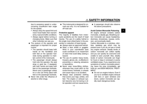
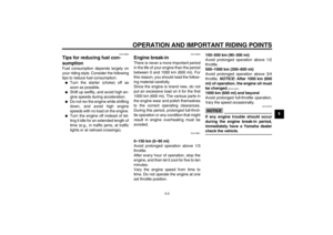
2. Remove the headlight bulb cover.3. Remove the headlight bulb holder
(together with the bulb) by turning
it counterclockwise.
4. Remove the burnt-out bulb by
pushing it in and turning it counter-
clockwise.5. Place a new bulb into the holder,
push it in, and then turn it clock-
wise until it stops.
6. Install the bulb holder (together
with the bulb) by turning it clock-
wise.
7. Install the headlight bulb cover.
8. Install the cowling.
9. Have a Yamaha dealer adjust the
headlight beam if necessary.
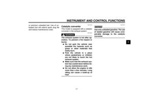
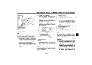
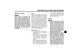
1. Headlight bulb cover
1. Headlight bulb holder
2. Headlight bulb
1
1
2
1. Do not touch the glass part of the bulb.
1
U40BE0E0.book Page 27 Wednesday, January 7, 2009 10:05 AM
Page 58 of 80
PERIODIC MAINTENANCE AND ADJUSTMENT
6-28
6
EAU47660
Replacing the tail/brake light
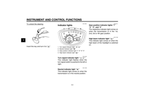
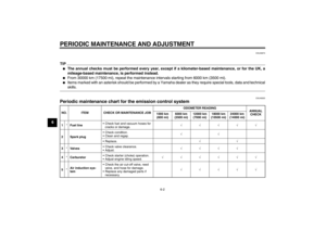
bulb 1. Remove the tail/brake light outer
lens by removing the screws.
2. Remove the inner lens by pulling it
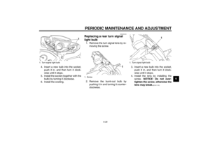
out.3. Remove the burnt-out bulb by
pushing it in and turning it counter-
clockwise.
4. Insert a new bulb into the socket,
push it in, and then turn it clock-
wise until it stops.
5. Place the inner lens in the original
position, and then install the outer
lens by installing the screws.
NOTICE: Do not overtighten the
screws, otherwise the lens may
break.
[ECA10681]EAU47740
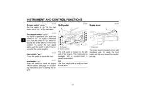
Replacing a front turn signal
light bulb 1. Remove cowling A. (See page
6-6.)
2. Remove the socket (together with
the bulb) by turning it counter-
clockwise.
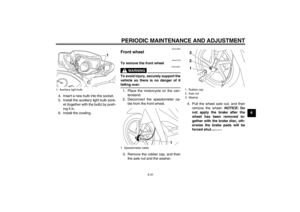
3. Remove the burnt-out bulb by
pushing it in and turning it counter-
clockwise.
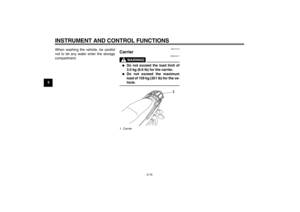
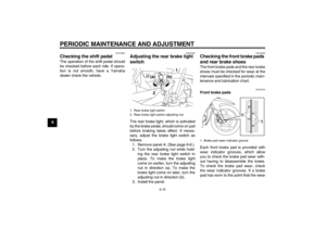
1. Outer lens
2. Screw
1. Inner lens
21
1
1. Tail/brake light bulb
1
1. Turn signal light bulb socket
1
U40BE0E0.book Page 28 Wednesday, January 7, 2009 10:05 AM
Page 59 of 80
PERIODIC MAINTENANCE AND ADJUSTMENT
6-29
6 4. Insert a new bulb into the socket,
push it in, and then turn it clock-
wise until it stops.
5. Install the socket (together with the
bulb) by turning it clockwise.
6. Install the cowling.
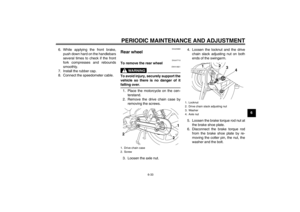
EAUS1610
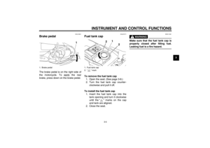
Replacing a rear turn signal
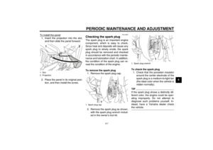
light bulb 1. Remove the turn signal lens by re-
moving the screw.
2. Remove the burnt-out bulb by
pushing it in and turning it counter-
clockwise.3. Insert a new bulb into the socket,
push it in, and then turn it clock-
wise until it stops.
4. Install the lens by installing the
screw. NOTICE: Do not over-
tighten the screw, otherwise the
lens may break.
[ECA11191]
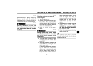
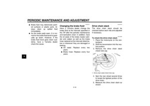
1. Turn signal light bulb
1
1. Screw
1
1. Turn signal light bulb
1
U40BE0E0.book Page 29 Wednesday, January 7, 2009 10:05 AM
Page 60 of 80
PERIODIC MAINTENANCE AND ADJUSTMENT
6-30
6
EAU47910
Replacing the license plate
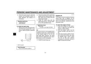
light bulb 1. Remove the license plate light cov-
er by removing the screw.
2. Remove the burnt-out bulb by pull-
ing it out from the socket.3. Insert a new bulb into the socket.
4. Install the license plate light cover
by installing the screw.
EAUW0343
Replacing an auxiliary light
bulb This model is equipped with two auxil-
iary lights. If an auxiliary light bulb burns
out, replace it as follows.
1. Remove cowling A. (See page
6-6.)
2. Remove the auxiliary light bulb
socket (together with the bulb) by
pulling it out.
3. Remove the burnt-out bulb by pull-
ing it out.
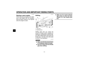
1. License plate light cover
2. Screw
1. License plate light bulb1
21
1. Auxiliary light bulb socket
1
U40BE0E0.book Page 30 Wednesday, January 7, 2009 10:05 AM
Page 61 of 80
PERIODIC MAINTENANCE AND ADJUSTMENT
6-31
6 4. Insert a new bulb into the socket.
5. Install the auxiliary light bulb sock-
et (together with the bulb) by push-
ing it in.
6. Install the cowling.
EAU24360
Front wheel
EAU47720
To remove the front wheel
WARNING
EWA10821
To avoid injury, securely support the
vehicle so there is no danger of itfalling over.
1. Place the motorcycle on the cen-
terstand.
2. Disconnect the speedometer ca-
ble from the front wheel.
3. Remove the rubber cap, and then
the axle nut and the washer.4. Pull the wheel axle out, and then
remove the wheel. NOTICE: Do
not apply the brake after the
wheel has been removed to-
gether with the brake disc, oth-
erwise the brake pads will be
forced shut.
[ECA11071]
1. Auxiliary light bulb
1
1. Speedometer cable
1
1. Rubber cap
2. Axle nut
3. Washer
123
U40BE0E0.book Page 31 Wednesday, January 7, 2009 10:05 AM
Page 62 of 80
PERIODIC MAINTENANCE AND ADJUSTMENT
6-32
6
EAU47730
To install the front wheel
1. Install the speedometer gear unit
into the wheel hub so that the pro-
jection on the wheel hub fits in ei-
ther slot of the speedometer gear
unit.2. Lift the wheel up between the fork
legs.
TIPMake sure that there is enough space
between the brake pads before insert-
ing the brake disc and that the retainer
in the speedometer gear unit fits overthe slot on the fork leg.3. Insert the wheel axle, and then in-
stall the washer and the axle nut.
4. Take the motorcycle off the center-
stand so that the front wheel is on
the ground.
5. Tighten the axle nut to the speci-
fied torque.
TIPWhen tightening the axle nut, hold the
wheel axle with a wrench to keep it fromturning.
1. Wheel axle
1
1. Projection
2. Speedometer gear unit
3. Slot
2
3
1
1. Retainer
2. SlotTightening torque:
Axle nut:
39 Nm (3.9 m·kgf, 28 ft·lbf)
U40BE0E0.book Page 32 Wednesday, January 7, 2009 10:05 AM
Page 63 of 80
PERIODIC MAINTENANCE AND ADJUSTMENT
6-33
6 6. While applying the front brake,
push down hard on the handlebars
several times to check if the front
fork compresses and rebounds
smoothly.
7. Install the rubber cap.
8. Connect the speedometer cable.
EAU25080
Rear wheel
EAU47710
To remove the rear wheel
WARNING
EWA10821
To avoid injury, securely support the
vehicle so there is no danger of itfalling over.
1. Place the motorcycle on the cen-
terstand.
2. Remove the drive chain case by
removing the screws.
3. Loosen the axle nut.4. Loosen the locknut and the drive
chain slack adjusting nut on both
ends of the swingarm.
5. Loosen the brake torque rod nut at
the brake shoe plate.
6. Disconnect the brake torque rod
from the brake shoe plate by re-
moving the cotter pin, the nut, the
washer and the bolt.1. Drive chain case
2. Screw
1
2
2
1. Locknut
2. Drive chain slack adjusting nut
3. Washer
4. Axle nut
12
3
4
U40BE0E0.book Page 33 Wednesday, January 7, 2009 10:05 AM
Page 64 of 80

PERIODIC MAINTENANCE AND ADJUSTMENT
6-34
67. Remove the brake pedal free play
adjusting nut, and then disconnect
the brake rod from the brake cam-
shaft lever.8. Remove the axle nut and the
washer, and then pull the wheel
axle out.9. Push the wheel forward, and then
remove the drive chain from the
rear sprocket.
TIPThe drive chain does not need to be
disassembled in order to remove andinstall the wheel.
10. Remove the wheel.
EAU47700
To install the rear wheel
1. Install the wheel by inserting the
wheel axle from the left-hand side.
2. Install the drive chain onto the rear
sprocket.
3. Install the washer and the axle nut.
4. Install the brake rod onto the brake
camshaft lever, and then install the
brake pedal free play adjusting nut
onto the brake rod.
5. Connect the brake torque rod to
the brake shoe plate by installing
the bolt, the washer and the nut.
6. Adjust the drive chain slack. (See
page 6-18.)
7. Tighten the brake torque rod nut
and axle nut to the specified
torques.
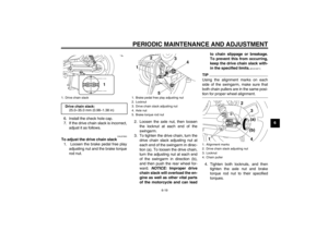
1. Brake torque rod
2. Brake torque rod cotter pin
3. Brake torque rod nut and bolt
1
2
3
1. Washer
2. Axle nut
3. Brake rod
4. Brake pedal free play adjusting nut
5. Brake camshaft lever
1. Wheel axle4
5
1
2
3
1
U40BE0E0.book Page 34 Wednesday, January 7, 2009 10:05 AM


 by turning it c")

 by push-
ing it in.
6. Install the cowling.
EAU24")

