Page 49 of 80

PERIODIC MAINTENANCE AND ADJUSTMENT
6-19
6 6. Install the check hole cap.
7. If the drive chain slack is incorrect,
adjust it as follows.
EAU37693
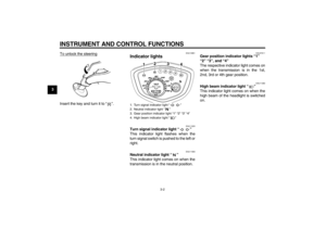
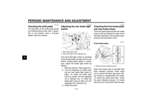
To adjust the drive chain slack
1. Loosen the brake pedal free play
adjusting nut and the brake torque
rod nut.2. Loosen the axle nut, then loosen
the locknut at each end of the
swingarm.
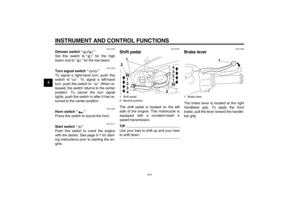
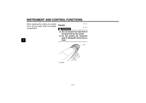
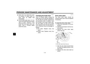
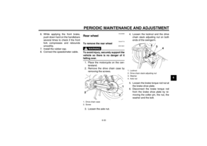
3. To tighten the drive chain, turn the
drive chain slack adjusting nut at
each end of the swingarm in direc-
tion (a). To loosen the drive chain,
turn the adjusting nut at each end
of the swingarm in direction (b),
and then push the rear wheel for-
ward. NOTICE: Improper drive
chain slack will overload the en-
gine as well as other vital parts
of the motorcycle and can leadto chain slippage or breakage.
To prevent this from occurring,
keep the drive chain slack with-
in the specified limits.
[ECA10571]
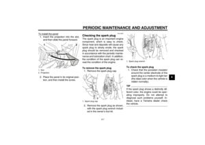
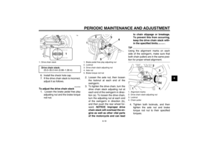
TIPUsing the alignment marks on each
side of the swingarm, make sure that
both chain pullers are in the same posi-tion for proper wheel alignment.
4. Tighten both locknuts, and then
tighten the axle nut and brake
torque rod nut to their specified
torques.
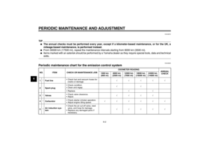
1. Drive chain slackDrive chain slack:
25.0–35.0 mm (0.98–1.38 in)
1
1. Brake pedal free play adjusting nut
2. Locknut
3. Drive chain slack adjusting nut
4. Axle nut
5. Brake torque rod nut
1
2
3
4
5
1. Alignment marks
2. Drive chain slack adjusting nut
3. Locknut
4. Chain puller
14
2
3
(a)
(b)
U40BE0E0.book Page 19 Wednesday, January 7, 2009 10:05 AM
Page 50 of 80

WARNING
EWA1")
PERIODIC MAINTENANCE AND ADJUSTMENT
6-20
6
TIPWhen tightening the axle nut, hold the
wheel axle with a wrench to keep it fromturning.
5. Adjust the brake pedal free play.
(See page 6-15.)
WARNING
EWA10660
After adjusting the brake pedal free
play, check the operation of thebrake light.
EAU23013
Cleaning and lubricating the
drive chain The drive chain must be cleaned and
lubricated at the intervals specified in
the periodic maintenance and lubrica-
tion chart, otherwise it will quickly wear
out, especially when riding in dusty or
wet areas. Service the drive chain as
follows.NOTICE
ECA10581
The drive chain must be lubricated
after washing the motorcycle andriding in the rain.
1. Remove all dirt and mud from the
drive chain with a brush or cloth.TIPFor a thorough cleaning, have a
Yamaha dealer remove the drive chainand soak it in solvent.
2. Spray Yamaha Chain and Cable
Lube or a high-quality spray-type
drive chain lubricant on both sides
and on the middle of the chain,making sure that all side plates
and rollers have been sufficiently
oiled.
Tightening torques:
Axle nut:
60 Nm (6.0 m·kgf, 43 ft·lbf)
Brake torque rod nut:
19 Nm (1.9 m·kgf, 13 ft·lbf)
U40BE0E0.book Page 20 Wednesday, January 7, 2009 10:05 AM
Page 51 of 80

PERIODIC MAINTENANCE AND ADJUSTMENT
6-21
6
EAU23101
Checking and lubricating the
cables The operation of all control cables and
the condition of the cables should be
checked before each ride, and the ca-
bles and cable ends should be lubricat-
ed if necessary. If a cable is damaged
or does not move smoothly, have a
Yamaha dealer check or replace it.
WARNING! Damage to the outer
sheath may interfere with proper ca-
ble operation and will cause the in-
ner cable to rust. Replace a
damaged cable as soon as possible
to prevent unsafe conditions.
[EWA10721]EAU23111
Checking and lubricating the
throttle grip and cable The operation of the throttle grip should
be checked before each ride. In addi-
tion, the cable should be lubricated at
the intervals specified in the periodic
maintenance chart.
EAU23153
Checking and lubricating the
brake lever The operation of the brake lever should
be checked before each ride, and the
lever pivots should be lubricated if nec-
essary.
Recommended lubricant:
Engine oil
Recommended lubricant:
Silicone grease
U40BE0E0.book Page 21 Wednesday, January 7, 2009 10:05 AM
Page 52 of 80

PERIODIC MAINTENANCE AND ADJUSTMENT
6-22
6
EAU23182
Checking and lubricating the
brake pedal The operation of the brake pedal
should be checked before each ride,
and the pedal pivot should be lubricat-
ed if necessary.
EAU23192
Checking and lubricating the
centerstand The operation of the centerstand
should be checked before each ride,
and the pivots and metal-to-metal con-
tact surfaces should be lubricated if
necessary.
WARNING
EWA11301
If the centerstand does not move up
and down smoothly, have a Yamaha
dealer check or repair it. Otherwise,
the centerstand could contact the
ground and distract the operator, re-sulting in a possible loss of control.
EAUM1650
Lubricating the swingarm piv-
ots The swingarm pivots must be lubricat-
ed at the intervals specified in the peri-
odic maintenance and lubrication chart.
Recommended lubricant:
Lithium-soap-based grease
Recommended lubricant:
Lithium-soap-based grease
Recommended lubricant:
Lithium-soap-based grease
U40BE0E0.book Page 22 Wednesday, January 7, 2009 10:05 AM
Page 53 of 80

PERIODIC MAINTENANCE AND ADJUSTMENT
6-23
6
EAU23272
Checking the front fork The condition and operation of the front
fork must be checked as follows at the
intervals specified in the periodic main-
tenance and lubrication chart.
To check the condition
Check the inner tubes for scratches,
damage and excessive oil leakage.
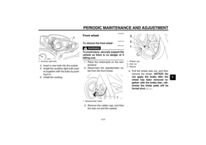
To check the operation
1. Place the vehicle on a level sur-
face and hold it in an upright posi-
tion. WARNING! To avoid injury,
securely support the vehicle so
there is no danger of it falling
over.
[EWA10751]
2. While applying the front brake,
push down hard on the handlebars
several times to check if the front
fork compresses and rebounds
smoothly.
NOTICE
ECA10590
If any damage is found or the front
fork does not operate smoothly,
have a Yamaha dealer check or re-pair it.
EAU45511
Checking the steering Worn or loose steering bearings may
cause danger. Therefore, the operation
of the steering must be checked as fol-
lows at the intervals specified in the pe-
riodic maintenance and lubrication
chart.
1. Place the vehicle on the center-
stand. WARNING! To avoid inju-
ry, securely support the vehicle
so there is no danger of it falling
over.
[EWA10751]
2. Hold the lower ends of the front
fork legs and try to move them for-
ward and backward. If any free
play can be felt, have a Yamaha
dealer check or repair the steering.
U40BE0E0.book Page 23 Wednesday, January 7, 2009 10:05 AM
Page 54 of 80

PERIODIC MAINTENANCE AND ADJUSTMENT
6-24
6
EAU23290
Checking the wheel bearings The front and rear wheel bearings must
be checked at the intervals specified in
the periodic maintenance and lubrica-
tion chart. If there is play in the wheel
hub or if the wheel does not turn
smoothly, have a Yamaha dealer check
the wheel bearings.
EAU47810
Battery This model is equipped with a VRLA
(Valve Regulated Lead Acid) battery.
There is no need to check the electro-
lyte or to add distilled water. However,
the battery lead connections need to be
checked and, if necessary, tightened.NOTICE
ECA10620
Never attempt to remove the battery
cell seals, as this would permanent-ly damage the battery.
WARNING
EWA10760
�
Electrolyte is poisonous and
dangerous since it contains sul-
furic acid, which causes severe
burns. Avoid any contact with
skin, eyes or clothing and al-
ways shield your eyes when
working near batteries. In case
of contact, administer the fol-
lowing FIRST AID.
EXTERNAL: Flush with plenty
of water.
INTERNAL: Drink large quan-
tities of water or milk and im-
mediately call a physician.EYES: Flush with water for 15
minutes and seek prompt
medical attention.
�
Batteries produce explosive hy-
drogen gas. Therefore, keep
sparks, flames, cigarettes, etc.,
away from the battery and pro-
vide sufficient ventilation when
charging it in an enclosed
space.
�
KEEP THIS AND ALL BATTER-
IES OUT OF THE REACH OFCHILDREN.
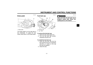
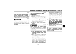
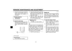
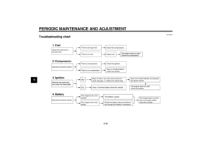
To access the battery
1. Open the seat. (See page 3-8.)
2. Remove the battery box cover by
removing the screw.
U40BE0E0.book Page 24 Wednesday, January 7, 2009 10:05 AM
Page 55 of 80

PERIODIC MAINTENANCE AND ADJUSTMENT
6-25
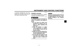
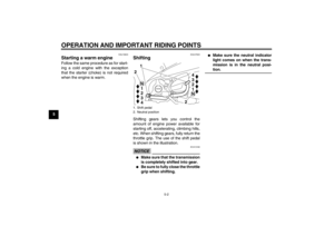
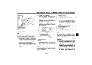
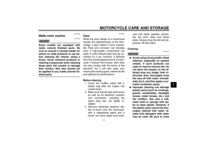
6 To remove the battery
1. Make sure the key is turned
to“”.
2. Disconnect the negative battery
lead first, then the positive battery
lead.3. Pull the battery out of its compart-
ment.
To charge the battery
Have a Yamaha dealer charge the bat-
tery as soon as possible if it seems to
have discharged. Keep in mind that the
battery tends to discharge more quickly
if the vehicle is equipped with optional
electrical accessories.
NOTICE
ECA16520
To charge a VRLA (Valve Regulated
Lead Acid) battery, a special (con-
stant-voltage) battery charger is re-
quired. Using a conventional batterycharger will damage the battery. If
you do not have access to a con-
stant-voltage battery charger, have a
Yamaha dealer charge your battery.
To store the battery
1. If the vehicle will not be used for
more than one month, remove the
battery, fully charge it, and then
place it in a cool, dry place. When
removing the battery, refer to “To
remove the battery”.
2. If the battery will be stored for more
than two months, check it at least
once a month and fully charge it if
necessary.
3. Fully charge the battery before in-
stallation.
4. After installation, make sure that
the battery leads are properly con-
nected to the battery terminals.NOTICE
ECA16530
Always keep the battery charged.
Storing a discharged battery cancause permanent battery damage.
1. Battery box cover
2. Screw
1
2
1. Battery
2. Positive battery lead (red)
3. Negative battery lead (black)
1
3
2
U40BE0E0.book Page 25 Wednesday, January 7, 2009 10:05 AM
Page 56 of 80
![YAMAHA T105 2009 Owners Manual PERIODIC MAINTENANCE AND ADJUSTMENT
6-26
6To install the battery
1. Place the battery in its compart-
ment. NOTICE: Be sure to install
the battery with its terminals
facing backward.
[ECA16590]
2. Ma](/manual-img/51/51341/w960_51341-55.png "YAMAHA T105 2009 Owners Manual PERIODIC MAINTENANCE AND ADJUSTMENT
6-26
6To install the battery
1. Place the battery in its compart-
ment. NOTICE: Be sure to install
the battery with its terminals
facing backward.
[ECA16590]
2. Ma")
PERIODIC MAINTENANCE AND ADJUSTMENT
6-26
6To install the battery
1. Place the battery in its compart-
ment. NOTICE: Be sure to install
the battery with its terminals
facing backward.
[ECA16590]
2. Make sure the key is turned
to“”.
3. Connect the positive battery lead
first, then the negative battery
lead.
4. Install the battery box cover by in-
stalling the screw.
5. Close the seat.
EAU47671
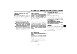
Replacing the fuse The fuse holder is located under the
seat. (See page 3-8.)
If the fuse is blown, replace it as fol-
lows.
1. Turn the key to“” and turn off all
electrical circuits.
2. Remove the battery box cover by
removing the screw.
3. Remove the blown fuse, and then
install a new fuse of the specified
amperage. WARNING! Do not
use a fuse of a higher amperage
rating than recommended toavoid causing extensive dam-
age to the electrical system and
possibly a fire.
[EWA15131]
4. Turn the key to“” and turn on
the electrical circuits to check if the
devices operate.
5. If the fuse immediately blows
again, have a Yamaha dealer
check the electrical system.
6. Install the battery box cover by in-
stalling the screw.
1. Battery box cover
2. Screw
1
2
1. Fuse
2. Spare fuseSpecified fuse:
10.0 A
12
U40BE0E0.book Page 26 Wednesday, January 7, 2009 10:05 AM