Page 41 of 80

PERIODIC MAINTENANCE AND ADJUSTMENT
6-11
6 4. Insert the air filter element into the
air filter case. NOTICE: Make sure
that the air filter element is prop-
erly seated in the air filter case.
The engine should never be op-
erated without the air filter ele-
ment installed, otherwise the
piston(s) and/or cylinder(s) may
become excessively worn.
[ECA10481]
5. Install the air filter case cover by in-
stalling the screws.
EAU21280
Adjusting the carburetor The carburetor is an important part of
the engine and requires very sophisti-
cated adjustment. Therefore, most car-
buretor adjustments should be left to a
Yamaha dealer, who has the neces-
sary professional knowledge and expe-
rience. The adjustment described in the
following section, however, may be ser-
viced by the owner as part of routine
maintenance.NOTICE
ECA10550
The carburetor has been set and ex-
tensively tested at the Yamaha fac-
tory. Changing these settings
without sufficient technical knowl-
edge may result in poor perfor-mance of or damage to the engine.
EAU21340
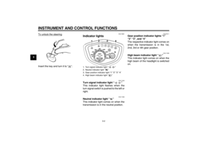
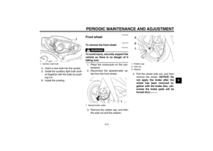
Adjusting the engine idling
speed The engine idling speed must be
checked and, if necessary, adjusted as
follows at the intervals specified in the
periodic maintenance and lubrication
chart.
The engine should be warm before
making this adjustment.TIP�
The engine is warm when it quickly
responds to the throttle.
�
A diagnostic tachometer is neededto make this adjustment.
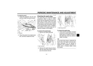
1. Attach the tachometer to the spark
plug lead.
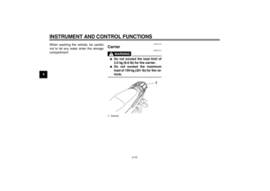
2. Check the engine idling speed
and, if necessary, adjust it to spec-
ification by turning the throttle stop
screw. To increase the engine
idling speed, turn the screw in di-
rection (a). To decrease the en-
gine idling speed, turn the screw in
direction (b).
U40BE0E0.book Page 11 Wednesday, January 7, 2009 10:05 AM
Page 42 of 80
PERIODIC MAINTENANCE AND ADJUSTMENT
6-12
6
TIPIf the specified idling speed cannot be
obtained as described above, have aYamaha dealer make the adjustment.
EAU21382
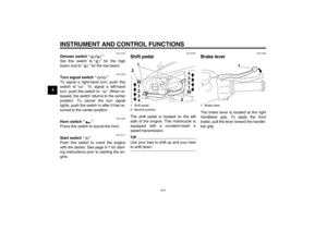
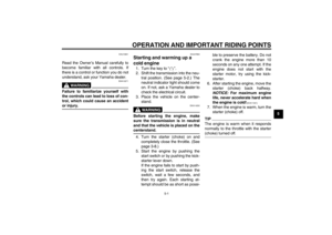
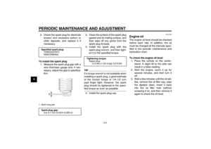
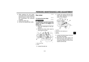
Checking the throttle cable
free play The throttle cable free play should mea-
sure 3.0–7.0 mm (0.12–0.28 in) at the
throttle grip. Periodically check the
throttle cable free play and, if neces-
sary, have a Yamaha dealer adjust it.
EAU21401
Valve clearance The valve clearance changes with use,
resulting in improper air-fuel mixture
and/or engine noise. To prevent this
from occurring, the valve clearance
must be adjusted by a Yamaha dealer
at the intervals specified in the periodic
maintenance and lubrication chart.
1. Throttle stop screwEngine idling speed:
1400–1600 r/min
(b)(a)
1
1
1. Throttle cable free play
1
U40BE0E0.book Page 12 Wednesday, January 7, 2009 10:05 AM
Page 43 of 80

PERIODIC MAINTENANCE AND ADJUSTMENT
6-13
6
EAU21582
Tires To maximize the performance, durabil-
ity, and safe operation of your motor-
cycle, note the following points
regarding the specified tires.
Tire air pressure
The tire air pressure should be checked
and, if necessary, adjusted before each
ride.
WARNING
EWA10501
Operation of this vehicle with im-
proper tire pressure may cause se-
vere injury or death from loss of
control.�
The tire air pressure must be
checked and adjusted on cold
tires (i.e., when the temperature
of the tires equals the ambient
temperature).
�
The tire air pressure must be ad-
justed in accordance with the
riding speed and with the total
weight of rider, passenger, car-
go, and accessories approvedfor this model.
WARNING
EWA10511
Never overload your vehicle. Opera-
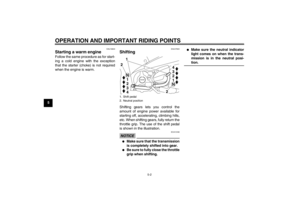
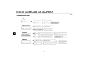
tion of an overloaded vehicle couldcause an accident.Tire inspection
The tires must be checked before each
ride. If the center tread depth reaches
the specified limit, if the tire has a nail or
glass fragments in it, or if the sidewall is
cracked, have a Yamaha dealer re-
place the tire immediately.
TIPThe tire tread depth limits may differ
from country to country. Always complywith the local regulations.
Tire air pressure (measured on cold
tires):
0–90 kg (0–198 lb):
Fr o nt :
200 kPa (2.00 kgf/cm², 29 psi)
Rear:
225 kPa (2.25 kgf/cm², 33 psi)
90–159 kg (198–351 lb):
Fr o nt :
200 kPa (2.00 kgf/cm², 29 psi)
Rear:
270 kPa (2.70 kgf/cm², 39 psi)
Maximum load*:
159 kg (351 lb)
* Total weight of rider, passenger, car-
go and accessories
1. Tire sidewall
2. Tire tread depth
Minimum tire tread depth (front and
rear):
1.6 mm (0.06 in)
U40BE0E0.book Page 13 Wednesday, January 7, 2009 10:05 AM
Page 44 of 80

PERIODIC MAINTENANCE AND ADJUSTMENT
6-14
6Tire information
This motorcycle is equipped with tube
tires.
WARNING
EWA10461
The front and rear tires should be of
the same make and design, other-
wise the handling characteristics of
the vehicle may be different, whichcould lead to an accident.
After extensive tests, only the tires list-
ed below have been approved for this
model by Yamaha Motor Co., Ltd.
WARNING
EWA10570
�
Have a Yamaha dealer replace
excessively worn tires. Besides
being illegal, operating themotorcycle with excessively
worn tires decreases riding sta-
bility and can lead to loss of
control.
�
The replacement of all wheel-
and brake-related parts, includ-
ing the tires, should be left to a
Yamaha dealer, who has the
necessary professional knowl-
edge and experience.
�
It is not recommended to patch
a punctured tube. If unavoid-
able, however, patch the tube
very carefully and replace it as
soon as possible with a high-quality product.
EAU22000
Cast wheels
WARNING
EWA10610
The wheels on this model are not de-
signed for use with tubeless tires.
Do not attempt to use tubeless tireson this model.
To maximize the performance, durabil-
ity, and safe operation of your motor-
cycle, note the following points
regarding the specified wheels.�
The wheel rims should be checked
for cracks, bends, warpage or
damage before each ride. If any
damage is found, have a Yamaha
dealer replace the wheel. Do not
attempt even the smallest repair to
the wheel. A deformed or cracked
wheel must be replaced.
�
The wheel should be balanced
whenever either the tire or wheel
has been changed or replaced. An
unbalanced wheel can result in
poor performance, adverse han-
dling characteristics, and a short-
ened tire life.
Front tire:
Size:
70/90-17M/C 38P
Manufacturer/model:
DUNLOP
Rear tire:
Size:
80/90-17M/C 50P
Manufacturer/model:
DUNLOP
U40BE0E0.book Page 14 Wednesday, January 7, 2009 10:05 AM
Page 45 of 80

PERIODIC MAINTENANCE AND ADJUSTMENT
6-15
6
�
Ride conservatively after changing
a tire since the tire must seat itself
on the rim properly. Failure to al-
low proper seating may cause tire
failure, which may result in dam-
age to the motorcycle and injury to
the rider.
EAU39812
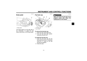
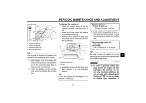
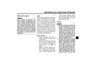
Adjusting the brake pedal free
play The brake pedal free play should mea-
sure 20.0–30.0 mm (0.79–1.18 in) at
the brake pedal end as shown. Period-
ically check the brake pedal free play
and, if necessary, adjust it as follows.
To increase the brake pedal free play,
turn the adjusting nut at the brake rod in
direction (a). To decrease the brake
pedal free play, turn the adjusting nut in
direction (b).
WARNING
EWA10680
�
After adjusting the drive chain
slack or removing and installing
the rear wheel, always check the
brake pedal free play.
�
If proper adjustment cannot be
obtained as described, have a
Yamaha dealer make this ad-
justment.
�
After adjusting the brake pedal
free play, check the operation ofthe brake light.
1. Brake pedal free play
1
1. Brake pedal free play adjusting nut
(a)(b)
1
U40BE0E0.book Page 15 Wednesday, January 7, 2009 10:05 AM
Page 46 of 80

PERIODIC MAINTENANCE AND ADJUSTMENT
6-16
6
EAU44820
Checking the shift pedal The operation of the shift pedal should
be checked before each ride. If opera-
tion is not smooth, have a Yamaha
dealer check the vehicle.
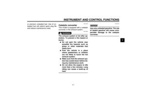
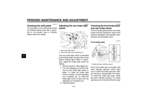
EAU22292
Adjusting the rear brake light
switch The rear brake light, which is activated
by the brake pedal, should come on just
before braking takes effect. If neces-
sary, adjust the brake light switch as
follows.
1. Remove panel A. (See page 6-6.)
2. Turn the adjusting nut while hold-
ing the rear brake light switch in
place. To make the brake light
come on earlier, turn the adjusting
nut in direction (a). To make the
brake light come on later, turn the
adjusting nut in direction (b).
3. Install the panel.
EAU22380
Checking the front brake pads
and rear brake shoes The front brake pads and the rear brake
shoes must be checked for wear at the
intervals specified in the periodic main-
tenance and lubrication chart.
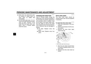
EAU22430
Front brake pads
Each front brake pad is provided with
wear indicator grooves, which allow
you to check the brake pad wear with-
out having to disassemble the brake.
To check the brake pad wear, check
the wear indicator grooves. If a brake
pad has worn to the point that the wear
1. Rear brake light switch
2. Rear brake light switch adjusting nut
21
(a) (b)
1. Brake pad wear indicator groove
1
1
U40BE0E0.book Page 16 Wednesday, January 7, 2009 10:05 AM
Page 47 of 80

PERIODIC MAINTENANCE AND ADJUSTMENT
6-17
6 indicator grooves have almost disap-
peared, have a Yamaha dealer replace
the brake pads as a set.
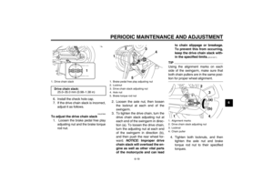
EAU22540
Rear brake shoes
The rear brake is provided with a wear
indicator, which allows you to check the
brake shoe wear without having to dis-
assemble the brake. To check the
brake shoe wear, check the position of
the wear indicator while applying the
brake. If a brake shoe has worn to the
point that the wear indicator reaches
the wear limit line, have a Yamaha
dealer replace the brake shoes as a
set.
EAU37001
Checking the front brake fluid
level Insufficient brake fluid may allow air to
enter the brake system, possibly caus-
ing it to become ineffective.
Before riding, check that the brake fluid
is above the minimum level mark and
replenish if necessary. A low brake fluid
level may indicate worn brake pads
and/or brake system leakage. If the
brake fluid level is low, be sure to check
the brake pads for wear and the brake
system for leakage.
Observe these precautions:
�
When checking the fluid level,
make sure that the top of the mas-
ter cylinder is level by turning the
handlebars.
�
Use only the recommended quality
brake fluid, otherwise the rubber
seals may deteriorate, causing
leakage and poor braking perfor-
mance.
TIPIf DOT 4 is not available, DOT 3 can beused.�
Refill with the same type of brake
fluid. Mixing fluids may result in a
harmful chemical reaction and
lead to poor braking performance.
�
Be careful that water does not en-
ter the master cylinder when refill-
ing. Water will significantly lower
the boiling point of the fluid and
may result in vapor lock.
1. Brake shoe wear limit line
2. Brake shoe wear indicator
2 1
1. Minimum level mark
1
Recommended brake fluid:
DOT 4
U40BE0E0.book Page 17 Wednesday, January 7, 2009 10:05 AM
Page 48 of 80

PERIODIC MAINTENANCE AND ADJUSTMENT
6-18
6
�
Brake fluid may deteriorate paint-
ed surfaces or plastic parts. Al-
ways clean up spilled fluid
immediately.
�
As the brake pads wear, it is nor-
mal for the brake fluid level to grad-
ually go down. However, if the
brake fluid level goes down sud-
denly, have a Yamaha dealer
check the cause.
EAU22721
Changing the brake fluid Have a Yamaha dealer change the
brake fluid at the intervals specified in
the TIP after the periodic maintenance
and lubrication chart. In addition, have
the oil seals of the brake master cylin-
der and caliper as well as the brake
hose replaced at the intervals listed be-
low or whenever they are damaged or
leaking.�
Oil seals: Replace every two
years.
�
Brake hose: Replace every four
years.
EAU22760
Drive chain slack The drive chain slack should be
checked before each ride and adjusted
if necessary.
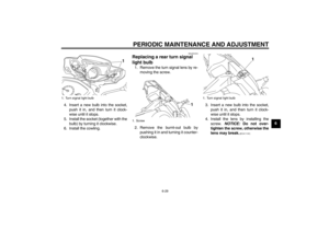
EAU47680
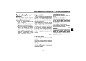
To check the drive chain slack
1. Place the motorcycle on the cen-
terstand.
2. Shift the transmission into the neu-
tral position.
3. Remove the drive chain slack
check hole cap.
4. Spin the rear wheel several times
to locate the tightest portion of the
drive chain.
5. Measure the drive chain slack as
shown.1. Drive chain slack check hole cap
1
U40BE0E0.book Page 18 Wednesday, January 7, 2009 10:05 AM