Page 207 of 2453
ET-22
Navigation Display
ENTERTAINMENT
17.Navigation Display
A: REMOVAL
1) Disconnect the ground cable from battery.
2) Remove the upper grille.
MOVAL, Air Vent Grille.>
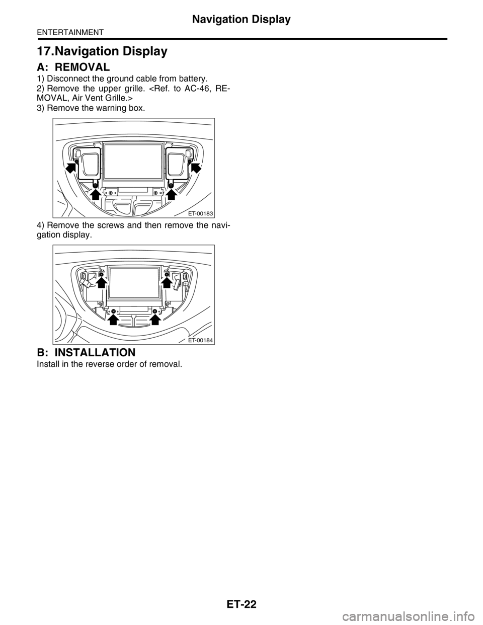
3) Remove the warning box.
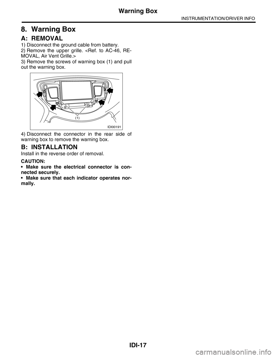
4) Remove the screws and then remove the navi-
gation display.
B: INSTALLATION
Install in the reverse order of removal.
ET-00183
ET-00184
Page 254 of 2453
EI-12
General Description
EXTERIOR/INTERIOR TRIM
12.INSTRUMENT PANEL
(1) Instrument panel upper ASSY (9)
Instrument panel lower cover
upper
(15) Console side panel upper RH
(2) Meter visor (16) Console side panel lower
(3) Center upper grille panel (10)
Instrument panel lower cover
under
(17) Glove box lid
(4) Air vent duct (18) Glove box panel
(5) Instrument panel side cover (11) Center console frame (19) Glove box lower cover
(6) Air vent side grille (12) Garnish RH
(7) Garnish LH (13) Steering support beam ASSYTightening torque: N·m (kgf-m, ft-lb)
(8) Garnish CTR (14) Console side panel upper LHT: 25 (25.5, 18)
EI-01269
TT
(2)
(5)
(1)
(8)
(6)
(19)
(11)
(12)
(15)
(17)
(5)
(6)
(3)(4)
(7)
(9)
(10)
(14)
(16)
(18)
(13)
(16)
Page 282 of 2453

EI-40
Instrument Panel Assembly
EXTERIOR/INTERIOR TRIM
17.Instrument Panel Assembly
A: REMOVAL
CAUTION:
Take care of the following when removing the
instrument panel from the vehicle body.
•Refer to “CAUTION” of “General Description”
before starting the work.
TION, General Description.>
•Be sure to disconnect each harness connec-
tor. Applying excessive pulling force may dam-
age the harness.
•Be careful to the harness of airbag system.
Damage of the harness may cause the air bag
system malfunction.
•Take care not to damage the interior trims
when removing the instrument panel from the
vehicle body.
NOTE:
•Putting alignment marks to each connector as
necessary facilitates the reassembly work.
•When storing the removed instrument panel, be
sure to prepare a table or the like to put the instru-
ment panel on in order to prevent damage.
1. INSTRUMENT PANEL UPPER
1) Disconnect the ground cable from battery and
wait for at least 20 seconds before starting work.
2) Remove the console box.
MOVAL, Console Box.>
3) Remove the instrument panel lower cover.
to EI-36, REMOVAL, Instrument Panel Lower Cov-
er.>
4) Remove the glove box.
AL, Glove Box.>
5) Remove the center console.
MOVAL, Center Console.>
6) Remove the audio unit.
MOVAL, Audio.>
7) Remove the combination meter assembly.
to IDI-11, REMOVAL, Combination Meter.>
8) Remove the upper grille.
PER GRILL, REMOVAL, Air Vent Grille.>
9) Remove the multi function display or navigation
monitor, and warning box.
MOVAL, Navigation Display.>
10) Remove the front pillar upper trim.
43, REMOVAL, Side Trim.>
11) Remove the mounting bolts of the passenger’s
side air bag module.
12) Remove the following screws.
•In combination meter house
•At the sides (left and right) of instrument panel
•Instrument panel center
EI-01327
EI-01328
EI-01330
EI-01329
Page 283 of 2453

EI-41
Instrument Panel Assembly
EXTERIOR/INTERIOR TRIM
13) Make sure that the instrument panel upper is
removed from the steering support beam
14) Disconnect the connectors, and remove the in-
strument panel from vehicle body.
15) Remove the heater vent duct.
REMOVAL, Heater Vent Duct.>
16) Remove the air vent grille.
MOVAL, Air Vent Grille.>
17) Remove the passenger airbag module.
to AB-16, REMOVAL, Passenger’s Airbag Mod-
ule.>
2. STEERING SUPPORT BEAM
1) Remove the instrument panel upper.
2) Remove the bolts, and then remove the knee
guard plate.
3) Remove the steering shaft from the steering
support beam.
Steering Column.>
4) Remove the bolts and remove the steering sup-
port beam.
3. INSTRUMENT PANEL ASSEMBLY
1) Disconnect the ground cable from battery and
wait for at least 20 seconds before starting work.
2) Remove the console box.
MOVAL, Console Box.>
3) Remove the instrument panel lower cover.
to EI-36, REMOVAL, Instrument Panel Lower Cov-
er.>
4) Remove the glove box.
AL, Glove Box.>
5) Remove the center console.
MOVAL, Center Console.>
6) Remove the front pillar upper trim.
43, REMOVAL, Side Trim.>
7) Remove the steering shaft from the steering
support beam.
Steering Column.>
8) Disconnect the connectors, and remove the in-
strument panel from vehicle body.
9) Remove the bolts and remove the steering sup-
port beam.
NOTE:
For positions of the mounting bolt of steering sup-
port beam, refer to the removal procedure of the
steering support beam.
10) Make sure that the each harness connector is
disconnected, and remove the instrument panel as-
sembly from the vehicle body.
NOTE:
Remove the passenger’s side door trim to facilitate
the work.
EI-01331
EI-01332
Page 372 of 2453
AC-46
Air Vent Grille
HVAC SYSTEM (HEATER, VENTILATOR AND A/C)
25.Air Vent Grille
A: REMOVAL
1. UPPER GRILL
1) Disconnect the ground cable from battery.
2) Lift the upper grill, and remove the catch on the
hazard switch side.
3) Hold the side of the monitor and remove the
catch on the upper, right and left sides.
4) Detach the connectors and remove the panel.
2. CENTER GRILLE
1) Disconnect the ground cable from battery.
2) Remove the front control panel.
FRONT, REMOVAL, Control Panel.>
3) Remove the screw, and remove the center grill
3. SIDE GRILLE
Remove the catch in 2 locations to remove the side
air vent grill.
4. ROOF GRILL
Remove the catch, and remove the roof air vent
grill.
B: INSTALLATION
Install in the reverse order of removal.
C: INSPECTION
1) Check that the direction and amount of air can
be adjusted smoothly.
2) Check that the adjustment can be maintained in
each position.
AC-01345
AC-01346
AC-01347
AC-01309
AC-001354
Page 456 of 2453
IDI-17
Warning Box
INSTRUMENTATION/DRIVER INFO
8. Warning Box
A: REMOVAL
1) Disconnect the ground cable from battery.
2) Remove the upper grille.
MOVAL, Air Vent Grille.>
3) Remove the screws of warning box (1) and pull
out the warning box.
4) Disconnect the connector in the rear side of
warning box to remove the warning box.
B: INSTALLATION
Install in the reverse order of removal.
CAUTION:
•Make sure the electrical connector is con-
nected securely.
•Make sure that each indicator operates nor-
mally.
IDI00191
(1)