2009 SUBARU TRIBECA Heat
[x] Cancel search: HeatPage 5 of 2453

AB-6
General Description
AIRBAG SYSTEM
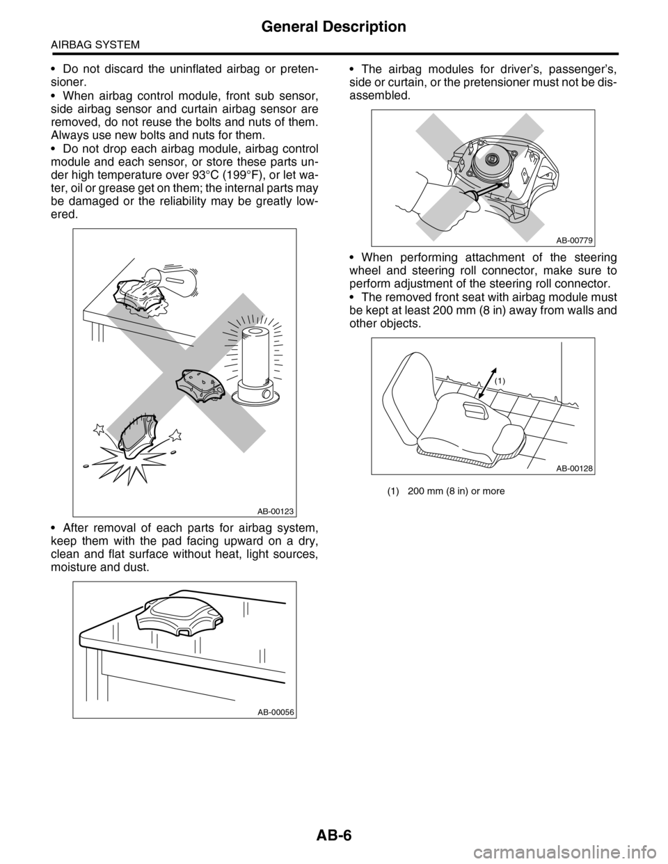
•Do not discard the uninflated airbag or preten-
sioner.
•When airbag control module, front sub sensor,
side airbag sensor and curtain airbag sensor are
removed, do not reuse the bolts and nuts of them.
Always use new bolts and nuts for them.
•Do not drop each airbag module, airbag control
module and each sensor, or store these parts un-
der high temperature over 93°C (199°F), or let wa-
ter, oil or grease get on them; the internal parts may
be damaged or the reliability may be greatly low-
ered.
•After removal of each parts for airbag system,
keep them with the pad facing upward on a dry,
clean and flat surface without heat, light sources,
moisture and dust.
•The airbag modules for driver’s, passenger’s,
side or curtain, or the pretensioner must not be dis-
assembled.
•When performing attachment of the steering
wheel and steering roll connector, make sure to
perform adjustment of the steering roll connector.
•The removed front seat with airbag module must
be kept at least 200 mm (8 in) away from walls and
other objects.
AB-00123
AB-00056
(1) 200 mm (8 in) or more
AB-00779
AB-00128
(1)
Page 20 of 2453

AB-21
Airbag Control Module
AIRBAG SYSTEM
8. Airbag Control Module
A: REMOVAL
CAUTION:
•Do not disassemble the airbag control mod-
ule.
•If the airbag control module is deformed or if
the fault occurs by water, replace the airbag
control module with a new one.
•Do not drop the airbag control module.
•After removal, keep the airbag control mod-
ule on a dry, clean surface away from moisture,
heat and dust.
1) Turn the ignition switch to OFF.
2) Disconnect the ground cable from battery and
wait for at least 20 seconds before starting work.
3) Remove the center console.
4) Remove the console box.
5) Remove the instrument panel lower cover.
er.>
6) Remove the glove box.
7) Remove the audio unit.
8) Remove the screws, and remove the center con-
sole frame.
9) Disconnect the connector from airbag control
module.
10) Remove the bolts and remove airbag control
module.
B: INSTALLATION
CAUTION:
•Do not reuse the bolt and nut.
•Always use new bolts and nuts for them.
•Be sure to put the water protection cover
over the connector.
Install in the reverse order of removal.
Tightening torque:
25 N·m (2.5 kgf-m, 18.1 ft-lb)
C: INSPECTION
Check for the following, and replace the damaged
parts with new parts.
•Control module, connector, and mounting brack-
et are damaged.
•Airbag is deployed.
•Side airbag is deployed.
•Curtain airbag is deployed.
AB-01280
AB-00759
Page 29 of 2453

AB(diag)-5
General Description
AIRBAG SYSTEM (DIAGNOSTICS)
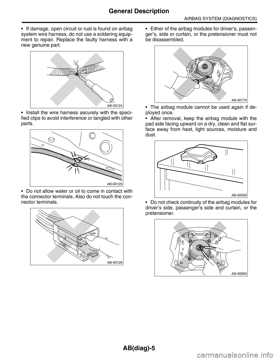
•If damage, open circuit or rust is found on airbag
system wire harness, do not use a soldering equip-
ment to repair. Replace the faulty harness with a
new genuine part.
•Install the wire harness securely with the speci-
fied clips to avoid interference or tangled with other
parts.
•Do not allow water or oil to come in contact with
the connector terminals. Also do not touch the con-
nector terminals.
•Either of the airbag modules for driver’s, passen-
ger’s, side or curtain, or the pretensioner must not
be disassembled.
•The airbag module cannot be used again if de-
ployed once.
•After removal, keep the airbag module with the
pad side facing upward on a dry, clean and flat sur-
face away from heat, light sources, moisture and
dust.
•Do not check continuity of the airbag modules for
driver’s side, passenger’s side and curtain, or the
pretensioner.
AB-00124
AB-00125
AB-00126
AB-00779
AB-00056
AB-00006
Page 257 of 2453

EI-15
General Description
EXTERIOR/INTERIOR TRIM
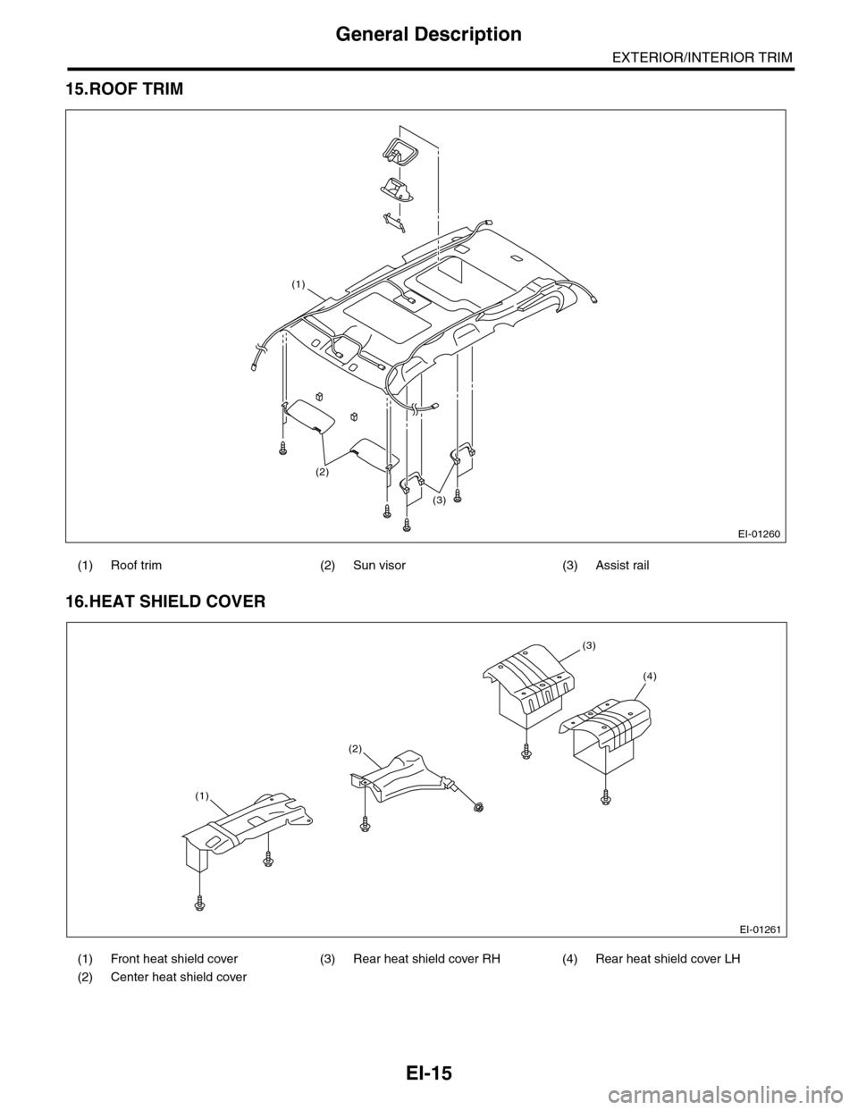
15.ROOF TRIM
16.HEAT SHIELD COVER
(1) Roof trim (2) Sun visor (3) Assist rail
(1) Front heat shield cover (3) Rear heat shield cover RH (4) Rear heat shield cover LH
(2) Center heat shield cover
EI-01260
(3)
(2)
(1)
EI-01261
(1)
(2)
(3)
(4)
Page 267 of 2453

EI-25
Front Bumper
EXTERIOR/INTERIOR TRIM
3) Deep damage such as a break or hole that requires filling
Much of the peripheral grained surface must be sacrificed for repair. The degree of restoration is not really
worth the expense. (The surface, however, will become almost flush with adjacent areas. )
Recommended repair kit: PP Part Repair Kit (NRM)
Process
No.Process name Job contents
1Bumper removalRemove the bumper as required.
2Removal of partsRemove the parts built into bumper as required.
3Bumper placement
Place the bumper on a paint worktable as
required.
It is recommended to use the paint worktable
conforming to internal shape of bumper.
(1) Bumper
(2) Set bumper section
4Surface prepara-
tion
Remove dust, oil, etc. from areas to be repaired and surrounding areas, using a suitable solvent
(NRM No. 900 Precleno, white gasoline, or alcohol, etc.).
5Cutting
If the damage is a crack or a hole, cut a guide
slit of 20 to 30 mm (0.79 to 1.18 in) in length
along the crack or hole up to the bumper base
surface. Next, use a knife or grinder to carve a
V- s h a p e d g r o o ve i n t h e a r e a f o r r e p a i r.
(1) Paint surface
(2) PP base surface
(3) 20 — 30 mm (0.79 — 1.18 in)
(4) 3 mm (0.12 in)
6Sanding (I) Grind beveled surface with sand paper (#40 — #60) to smooth finish.
7Cleaning Clean the sanded surface with the same solvent as used in Procedure 4.
8Temporary welding
Grind the side just opposite the beveled area with sand paper (#40 — #60) and clean using a
solvent.
Te m p o r a r i l y s p o t - w e l d t h e s i d e , u s i n g P P w e l d i n g r o d a n d h e a t e r g u n .
(1) Welded point (Use heater gun and PP welding rod)
(2) PP base surface
(3) Beveled section
NOTE:•Do not melt welding rod until it flows out. This results in reduced strength.
•Leave the welded spot unattended until it cools completely.
EI-00234(2)
(1)
EI-00235
(4)(2)
(1)(3)
EI-00236
(1)
(2)
(3)
Page 268 of 2453

EI-26
Front Bumper
EXTERIOR/INTERIOR TRIM
9Welding
Using a heater gun and PP welding rod, weld the beveled spot while melting both the rod and
damaged area.
(1) Welding rod
(2) Melt hatched area
(3) Section
NOTE:•Melt the sections indicated by hatched area.
•Do not melt the welding rod until it flows out, in order to provide strength.
•Always keep the heater gun 1 to 2 cm (0.4 to 0.8 in) away from the welding spot.
•Leave the welded spot unattended until it cools completely.
10 Sanding (II)
Remove excess part of weld with a putty knife. If a drill or disc wheel is used instead of the knife,
operate it at a rate lower than 1,500 rpm and grind the excess part little by little. A higher rpm will
cause the PP substrate to melt from the heat.
Sand the welded spot smooth with #240 sand paper.
11 MaskingMask the black substrate section using masking tape.
Recommended masking tape: Nichiban No. 533 or equivalent
12Cleaning/degreas-
ingCompletely clean the entire coated area, using solvent similar to that used in Procedure 4.
13 Primer coating
Apply a coat of primer to the repaired surface and its surrounding areas. Mask these areas, if
necessary.
Recommended primer: Mp/ 364 PP Primer
NOTE:Be sure to apply a coat of primer using a spray gun at a pressure of 245 — 343 kPa (2.5 — 3.5
kg/cm2, 36 — 50 psi).
14 Leave unattended
Leave the repaired area unattended at 20°C (68°F) for 10 to 15 minutes until primer is half-dry.
NOTE:If dirt or dust comes in contact with the coated area, wipe it off with a cloth dampened with alcohol.
(Do not use thinner since the coated area tends to melt.)
15Primer surfacer
coating
Apply primer surfacer to the repaired area two or three times at an interval of 3 - 5 minutes.
Recommended surfacer:
•UPS 300 Flex Primer
•No. 303 UPS 300 Exclusive hardener
•NPS 725 Exclusive Reducer (thinner)
•Mixture ratio:
2 : 1 (UPS 300 : No. 303)
•Viscosity: 12 — 14 sec./20°C (68°F)
• Coating film thickness: 40 — 50 µ
16 Drying Allow the coated surface to dry for 60 minutes at 20°C (68°F) [or 30 minutes at 60°C (140°F)].
17 Sanding (III) Sand the coated surface and its surrounding areas using #400 sand paper and water.
Process
No.Process name Job contents
(1)
(2)
(2)
(3)
EI-00237
EI-00042
Page 275 of 2453

EI-33
Side Garnish
EXTERIOR/INTERIOR TRIM
(3) Apply masking tape around the double-sid-
ed tape remaining on the surface of body or
spoiler.
(4) Apply solvent uniformly on the double-sided
tape using a brush.
CAUTION:
•Do not use solvent to the body which has
been repaired with lacquer paint.
•Wipe off immediately when the solvent is at-
tached on surface of the body or spoiler.
Solvent:
3M 8907 or equivalent
(5) Cover the area where solvent is applied us-
ing plastic wrap (A), and then heat the double-
sided tape for 5 to 10 minutes in 40 — 60°C
(104 — 140°F) using a heat lamp (B).
CAUTION:
Do not heat the double-sided tape until the sur-
face becomes white and excessively dried.
(6) Remove the double-sided tape using a plas-
tic spatula.
(7) After completely removing the double-sided
tape, detach the masking tape and clean the
surface using a cotton cloth damped with white
gasoline.
3) Remove the front fender garnish and rear quar-
ter garnish.
4) Remove the door garnish.
B: INSTALLATION
1) Apply primer to the door garnish surface where
the double-sided tape is to be adhered, and then
adhere the double-sided tape as shown in the fig-
ure.
Primer:
3M K-500 or equivalent
Double-sided tape:
3M 5531-5 or equivalent
2) Heat the adhering part using a heat lamp.
Body side: 40 — 60°C (104 — 140°F)
Door garnish side: 20 — 30°C (68 — 86°F)
3) Peel off the backing sheet of double-sided tape,
align the clip position, and then adhere the tape to
the body while taking care to avoid air entering.
CAUTION:
To keep the adhesion, do not wash the vehicle
within 24 hours from installation.
EI-00155
(A)
(B)
EI-00156
(A)
(B)
(1) Double-sided tape:
Thickness = 1.2 mm (0.047 in)
Width 5mm (0.197in)
EI-00536
(1)(1)
Page 283 of 2453

EI-41
Instrument Panel Assembly
EXTERIOR/INTERIOR TRIM
13) Make sure that the instrument panel upper is
removed from the steering support beam
14) Disconnect the connectors, and remove the in-
strument panel from vehicle body.
15) Remove the heater vent duct.
16) Remove the air vent grille.
17) Remove the passenger airbag module.
ule.>
2. STEERING SUPPORT BEAM
1) Remove the instrument panel upper.
2) Remove the bolts, and then remove the knee
guard plate.
3) Remove the steering shaft from the steering
support beam.
4) Remove the bolts and remove the steering sup-
port beam.
3. INSTRUMENT PANEL ASSEMBLY
1) Disconnect the ground cable from battery and
wait for at least 20 seconds before starting work.
2) Remove the console box.
3) Remove the instrument panel lower cover.
er.>
4) Remove the glove box.
5) Remove the center console.
6) Remove the front pillar upper trim.
7) Remove the steering shaft from the steering
support beam.
8) Disconnect the connectors, and remove the in-
strument panel from vehicle body.
9) Remove the bolts and remove the steering sup-
port beam.
NOTE:
For positions of the mounting bolt of steering sup-
port beam, refer to the removal procedure of the
steering support beam.
10) Make sure that the each harness connector is
disconnected, and remove the instrument panel as-
sembly from the vehicle body.
NOTE:
Remove the passenger’s side door trim to facilitate
the work.
EI-01331
EI-01332