2009 SUBARU TRIBECA Harness
[x] Cancel search: HarnessPage 2263 of 2453
CS-11
AT Shift Lock Control System
CONTROL SYSTEMS
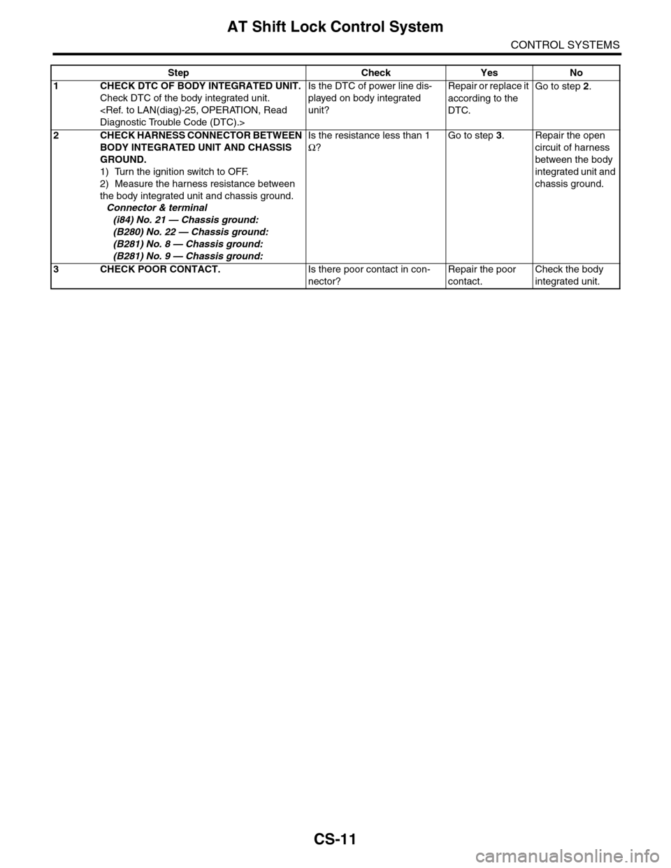
Step Check Yes No
1CHECK DTC OF BODY INTEGRATED UNIT.
Check DTC of the body integrated unit.
Is the DTC of power line dis-
played on body integrated
unit?
Repair or replace it
according to the
DTC.
Go to step 2.
2CHECK HARNESS CONNECTOR BETWEEN
BODY INTEGRATED UNIT AND CHASSIS
GROUND.
1) Turn the ignition switch to OFF.
2) Measure the harness resistance between
the body integrated unit and chassis ground.
Connector & terminal
(i84) No. 21 — Chassis ground:
(B280) No. 22 — Chassis ground:
(B281) No. 8 — Chassis ground:
(B281) No. 9 — Chassis ground:
Is the resistance less than 1
Ω?
Go to step 3.Repair the open
circuit of harness
between the body
integrated unit and
chassis ground.
3CHECK POOR CONTACT.Is there poor contact in con-
nector?
Repair the poor
contact.
Check the body
integrated unit.
Page 2265 of 2453
CS-13
AT Shift Lock Control System
CONTROL SYSTEMS
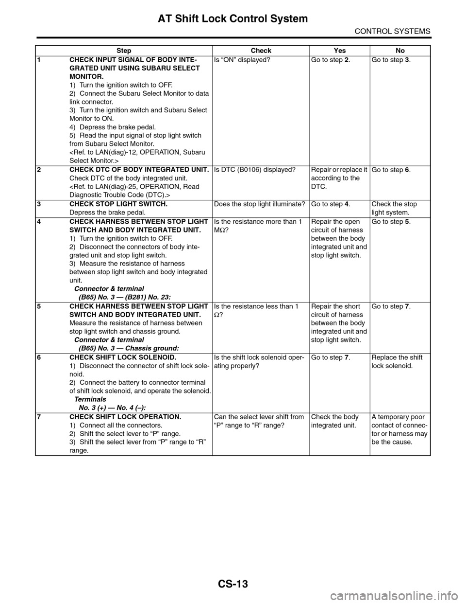
Step Check Yes No
1CHECK INPUT SIGNAL OF BODY INTE-
GRATED UNIT USING SUBARU SELECT
MONITOR.
1) Turn the ignition switch to OFF.
2) Connect the Subaru Select Monitor to data
link connector.
3) Turn the ignition switch and Subaru Select
Monitor to ON.
4) Depress the brake pedal.
5) Read the input signal of stop light switch
from Subaru Select Monitor.
Is “ON” displayed? Go to step 2.Go to step 3.
2CHECK DTC OF BODY INTEGRATED UNIT.
Check DTC of the body integrated unit.
Is DTC (B0106) displayed? Repair or replace it
according to the
DTC.
Go to step 6.
3CHECK STOP LIGHT SWITCH.
Depress the brake pedal.
Does the stop light illuminate? Go to step 4.Check the stop
light system.
4CHECK HARNESS BETWEEN STOP LIGHT
SWITCH AND BODY INTEGRATED UNIT.
1) Turn the ignition switch to OFF.
2) Disconnect the connectors of body inte-
grated unit and stop light switch.
3) Measure the resistance of harness
between stop light switch and body integrated
unit.
Connector & terminal
(B65) No. 3 — (B281) No. 23:
Is the resistance more than 1
MΩ?
Repair the open
circuit of harness
between the body
integrated unit and
stop light switch.
Go to step 5.
5CHECK HARNESS BETWEEN STOP LIGHT
SWITCH AND BODY INTEGRATED UNIT.
Measure the resistance of harness between
stop light switch and chassis ground.
Connector & terminal
(B65) No. 3 — Chassis ground:
Is the resistance less than 1
Ω?
Repair the short
circuit of harness
between the body
integrated unit and
stop light switch.
Go to step 7.
6CHECK SHIFT LOCK SOLENOID.
1) Disconnect the connector of shift lock sole-
noid.
2) Connect the battery to connector terminal
of shift lock solenoid, and operate the solenoid.
Te r m i n a l s
No. 3 (+) — No. 4 (–):
Is the shift lock solenoid oper-
ating properly?
Go to step 7.Replace the shift
lock solenoid.
7CHECK SHIFT LOCK OPERATION.
1) Connect all the connectors.
2) Shift the select lever to “P” range.
3) Shift the select lever from “P” range to “R”
range.
Can the select lever shift from
“P” range to “R” range?
Check the body
integrated unit.
A temporary poor
contact of connec-
tor or harness may
be the cause.
Page 2267 of 2453
CS-15
AT Shift Lock Control System
CONTROL SYSTEMS
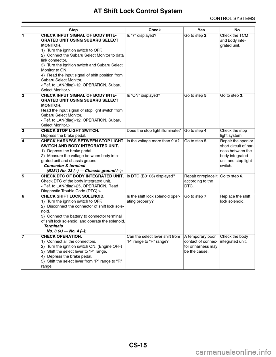
Step Check Yes No
1CHECK INPUT SIGNAL OF BODY INTE-
GRATED UNIT USING SUBARU SELECT
MONITOR.
1) Turn the ignition switch to OFF.
2) Connect the Subaru Select Monitor to data
link connector.
3) Turn the ignition switch and Subaru Select
Monitor to ON.
4) Read the input signal of shift position from
Subaru Select Monitor.
Is “7” displayed? Go to step 2.Check the TCM
and body inte-
grated unit.
2CHECK INPUT SIGNAL OF BODY INTE-
GRATED UNIT USING SUBARU SELECT
MONITOR.
Read the input signal of stop light switch from
Subaru Select Monitor.
Is “ON” displayed? Go to step 5.Go to step 3.
3CHECK STOP LIGHT SWITCH.
Depress the brake pedal.
Does the stop light illuminate? Go to step 4.Check the stop
light system.
4CHECK HARNESS BETWEEN STOP LIGHT
SWITCH AND BODY INTEGRATED UNIT.
1) Depress the brake pedal.
2) Measure the voltage between body inte-
grated unit and chassis ground.
Connector & terminal
(B281) No. 23 (+) — Chassis ground (–):
Is the voltage more than 9 V? Go to step 5.Repair the open or
short circuit of har-
ness between the
body integrated
unit and stop light
switch.
5CHECK DTC OF BODY INTEGRATED UNIT.
Check DTC of the body integrated unit.
Is DTC (B0106) displayed? Repair or replace it
according to the
DTC.
Go to step 6.
6CHECK SHIFT LOCK SOLENOID.
1) Turn the ignition switch to OFF.
2) Disconnect the connector of shift lock sole-
noid.
3) Connect the battery to connector terminal
of shift lock solenoid, and operate the solenoid.
Te r m i n a l s
No. 3 (+) — No. 4 (–):
Is the shift lock solenoid oper-
ating properly?
Go to step 7.Replace the shift
lock solenoid.
7CHECK OPERATION.
1) Connect all the connectors.
2) Turn the ignition switch ON. (Engine OFF)
3) Shift the select lever to “P” range.
4) Depress the brake pedal.
5) Shift the select lever from “P” range to “R”
range.
Can the select lever shift from
“P” range to “R” range?
A temporary poor
contact of connec-
tor or harness may
be the cause.
Check the body
integrated unit.
Page 2269 of 2453
CS-17
AT Shift Lock Control System
CONTROL SYSTEMS
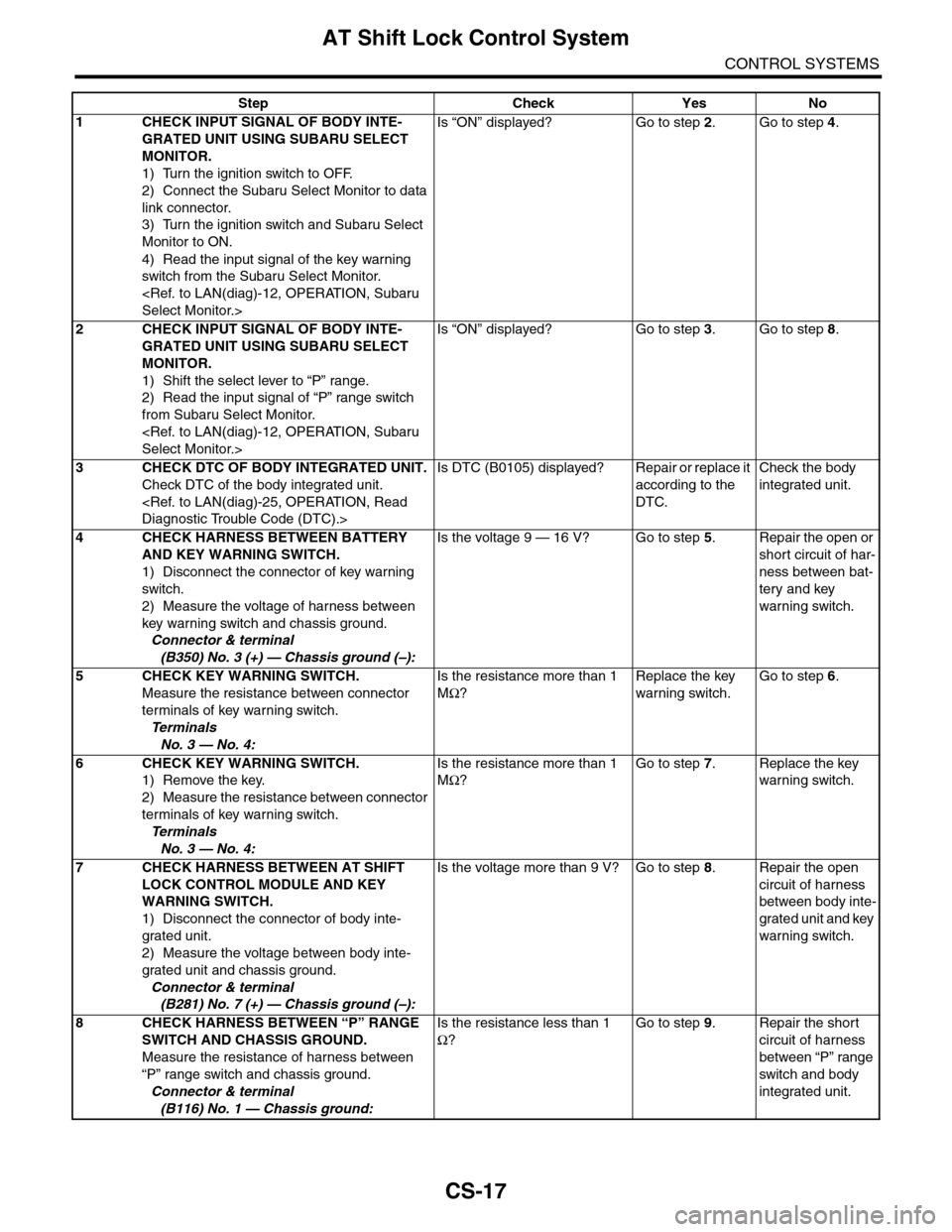
Step Check Yes No
1CHECK INPUT SIGNAL OF BODY INTE-
GRATED UNIT USING SUBARU SELECT
MONITOR.
1) Turn the ignition switch to OFF.
2) Connect the Subaru Select Monitor to data
link connector.
3) Turn the ignition switch and Subaru Select
Monitor to ON.
4) Read the input signal of the key warning
switch from the Subaru Select Monitor.
Is “ON” displayed? Go to step 2.Go to step 4.
2CHECK INPUT SIGNAL OF BODY INTE-
GRATED UNIT USING SUBARU SELECT
MONITOR.
1) Shift the select lever to “P” range.
2) Read the input signal of “P” range switch
from Subaru Select Monitor.
Is “ON” displayed? Go to step 3.Go to step 8.
3CHECK DTC OF BODY INTEGRATED UNIT.
Check DTC of the body integrated unit.
Is DTC (B0105) displayed? Repair or replace it
according to the
DTC.
Check the body
integrated unit.
4CHECK HARNESS BETWEEN BATTERY
AND KEY WARNING SWITCH.
1) Disconnect the connector of key warning
switch.
2) Measure the voltage of harness between
key warning switch and chassis ground.
Connector & terminal
(B350) No. 3 (+) — Chassis ground (–):
Is the voltage 9 — 16 V? Go to step 5.Repair the open or
short circuit of har-
ness between bat-
tery and key
warning switch.
5 CHECK KEY WARNING SWITCH.
Measure the resistance between connector
terminals of key warning switch.
Te r m i n a l s
No. 3 — No. 4:
Is the resistance more than 1
MΩ?
Replace the key
warning switch.
Go to step 6.
6 CHECK KEY WARNING SWITCH.
1) Remove the key.
2) Measure the resistance between connector
terminals of key warning switch.
Te r m i n a l s
No. 3 — No. 4:
Is the resistance more than 1
MΩ?
Go to step 7.Replace the key
warning switch.
7CHECK HARNESS BETWEEN AT SHIFT
LOCK CONTROL MODULE AND KEY
WARNING SWITCH.
1) Disconnect the connector of body inte-
grated unit.
2) Measure the voltage between body inte-
grated unit and chassis ground.
Connector & terminal
(B281) No. 7 (+) — Chassis ground (–):
Is the voltage more than 9 V? Go to step 8.Repair the open
circuit of harness
between body inte-
grated unit and key
warning switch.
8CHECK HARNESS BETWEEN “P” RANGE
SWITCH AND CHASSIS GROUND.
Measure the resistance of harness between
“P” range switch and chassis ground.
Connector & terminal
(B116) No. 1 — Chassis ground:
Is the resistance less than 1
Ω?
Go to step 9.Repair the short
circuit of harness
between “P” range
switch and body
integrated unit.
Page 2270 of 2453
CS-18
AT Shift Lock Control System
CONTROL SYSTEMS
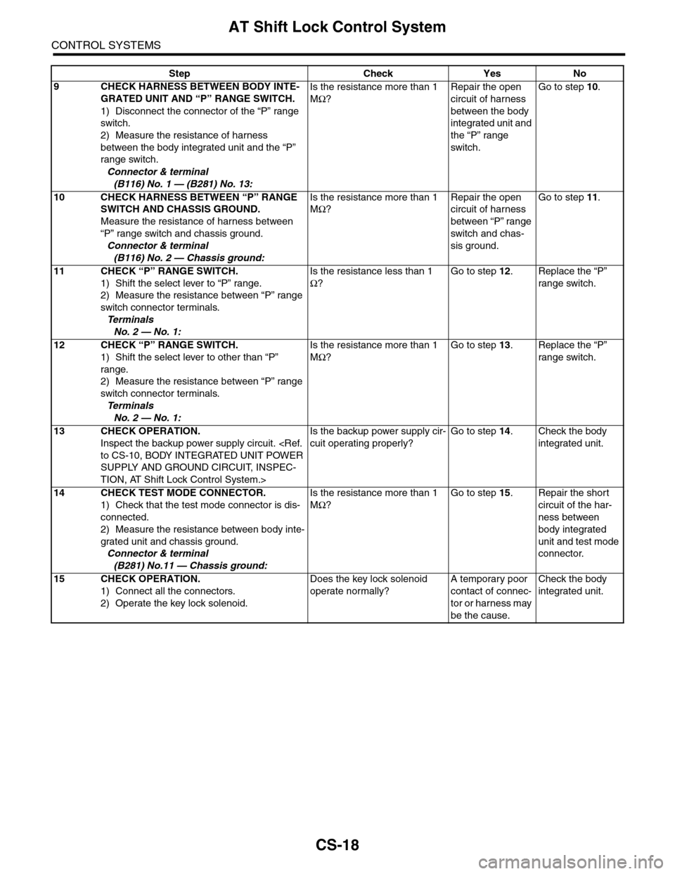
9CHECK HARNESS BETWEEN BODY INTE-
GRATED UNIT AND “P” RANGE SWITCH.
1) Disconnect the connector of the “P” range
switch.
2) Measure the resistance of harness
between the body integrated unit and the “P”
range switch.
Connector & terminal
(B116) No. 1 — (B281) No. 13:
Is the resistance more than 1
MΩ?
Repair the open
circuit of harness
between the body
integrated unit and
the “P” range
switch.
Go to step 10.
10 CHECK HARNESS BETWEEN “P” RANGE
SWITCH AND CHASSIS GROUND.
Measure the resistance of harness between
“P” range switch and chassis ground.
Connector & terminal
(B116) No. 2 — Chassis ground:
Is the resistance more than 1
MΩ?
Repair the open
circuit of harness
between “P” range
switch and chas-
sis ground.
Go to step 11.
11 CHECK “P” RANGE SWITCH.
1) Shift the select lever to “P” range.
2) Measure the resistance between “P” range
switch connector terminals.
Te r m i n a l s
No. 2 — No. 1:
Is the resistance less than 1
Ω?
Go to step 12.Replace the “P”
range switch.
12 CHECK “P” RANGE SWITCH.
1) Shift the select lever to other than “P”
range.
2) Measure the resistance between “P” range
switch connector terminals.
Te r m i n a l s
No. 2 — No. 1:
Is the resistance more than 1
MΩ?
Go to step 13.Replace the “P”
range switch.
13 CHECK OPERATION.
Inspect the backup power supply circuit.
SUPPLY AND GROUND CIRCUIT, INSPEC-
TION, AT Shift Lock Control System.>
Is the backup power supply cir-
cuit operating properly?
Go to step 14.Check the body
integrated unit.
14 CHECK TEST MODE CONNECTOR.
1) Check that the test mode connector is dis-
connected.
2) Measure the resistance between body inte-
grated unit and chassis ground.
Connector & terminal
(B281) No.11 — Chassis ground:
Is the resistance more than 1
MΩ?
Go to step 15.Repair the short
circuit of the har-
ness between
body integrated
unit and test mode
connector.
15 CHECK OPERATION.
1) Connect all the connectors.
2) Operate the key lock solenoid.
Does the key lock solenoid
operate normally?
A temporary poor
contact of connec-
tor or harness may
be the cause.
Check the body
integrated unit.
Step Check Yes No
Page 2271 of 2453
CS-19
Select Lever
CONTROL SYSTEMS
3. Select Lever
A: REMOVAL
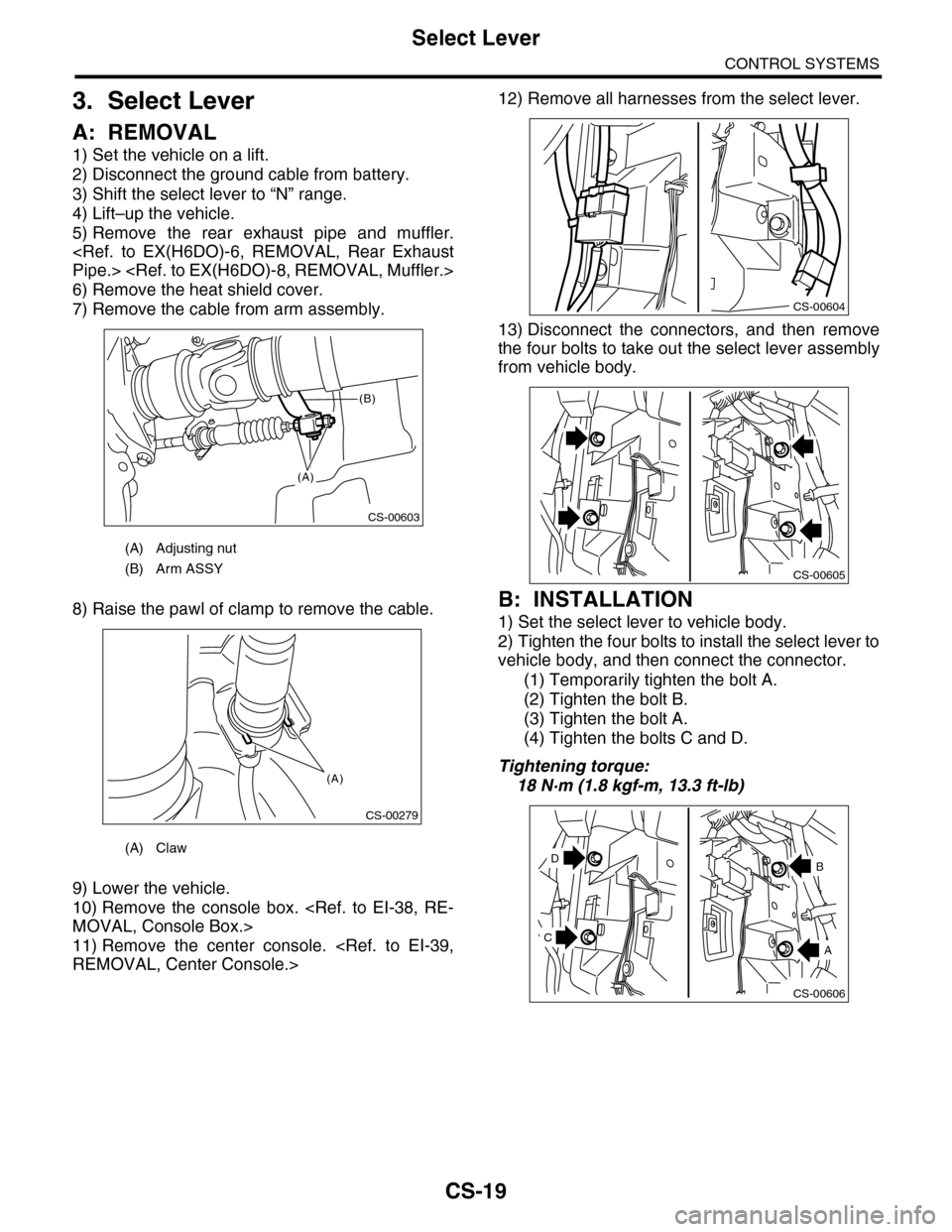
1) Set the vehicle on a lift.
2) Disconnect the ground cable from battery.
3) Shift the select lever to “N” range.
4) Lift–up the vehicle.
5) Remove the rear exhaust pipe and muffler.
6) Remove the heat shield cover.
7) Remove the cable from arm assembly.
8) Raise the pawl of clamp to remove the cable.
9) Lower the vehicle.
10) Remove the console box.
11) Remove the center console.
12) Remove all harnesses from the select lever.
13) Disconnect the connectors, and then remove
the four bolts to take out the select lever assembly
from vehicle body.
B: INSTALLATION
1) Set the select lever to vehicle body.
2) Tighten the four bolts to install the select lever to
vehicle body, and then connect the connector.
(1) Temporarily tighten the bolt A.
(2) Tighten the bolt B.
(3) Tighten the bolt A.
(4) Tighten the bolts C and D.
Tightening torque:
18 N·m (1.8 kgf-m, 13.3 ft-lb)
(A) Adjusting nut
(B) Arm ASSY
(A) Claw
CS-00603
(A)
(B)
CS-00279
(A)
CS-00604
CS-00605
CS-00606
D
A
B
C
Page 2277 of 2453
![SUBARU TRIBECA 2009 1.G Service Workshop Manual CS-25
Select Lever
CONTROL SYSTEMS
D: ASSEMBLY
1) Clean all the parts before assembly.
2) Apply grease [Multemp AC-D, and SH-W or
equivalent] to each part. <Ref. to CS-2, AT SE-
LECT LE SUBARU TRIBECA 2009 1.G Service Workshop Manual CS-25
Select Lever
CONTROL SYSTEMS
D: ASSEMBLY
1) Clean all the parts before assembly.
2) Apply grease [Multemp AC-D, and SH-W or
equivalent] to each part. <Ref. to CS-2, AT SE-
LECT LE](/manual-img/17/7322/w960_7322-2276.png)
CS-25
Select Lever
CONTROL SYSTEMS
D: ASSEMBLY
1) Clean all the parts before assembly.
2) Apply grease [Multemp AC-D, and SH-W or
equivalent] to each part.
tion.>
3) Assemble in the reverse order of disassembly.
NOTE:
•Refer to “COMPONENT” for each tightening
torque.
•When pressing in the shift position pin, insert
from the left side of the vehicle.
•Affix the harness of the shift button switch and
the mode change switch at the marked positions.
•Connect the terminals of all switches to the re-
spective connectors.
4) After completing installation, shift the select le-
ver from the “P” range to the “D” range, then check
whether or not the selection indicator in the combi-
nation meter and the select lever position matches.
Also check whether the pointer and position mark
matches, and what the operating force is.
E: INSPECTION
1) Inspect the removed parts by comparing with
new ones for deformation, damage and wear. Re-
pair or replace if defective.
2) Confirm the select lever operating condition be-
fore assembly. Normal if it operates smoothly. CS-00641
(A) Mode change switch (color code: Yellow)
(B) Shift button switch (color code: Brown)
(C) Mode change switch and shift button switch
ground (color code: White)
(D) Shift up switch (color code: Green)
(E) Shift up switch (color code: Gray)
(F) Shift up/down switch ground (color code: Blue)
(G) “P” range switch (wire color: Red)
(H) Shift lock solenoid (color code: Blue)
(I) Shift lock solenoid (color code: Black)
(J) Indicator lamp (color code: Blue)
CS-00642
5432112 11 10 9876
(J)
(J)(F)(E)(D)(A)(B)(C)
(H) (G)(I)
Page 2287 of 2453
WI-3
Basic Diagnostic Procedure
WIRING SYSTEM
1. Basic Diagnostic Procedure
A: BASIC PROCEDURES
1. GENERAL DESCRIPTION
The most important purpose of diagnostics is to
quickly determine which part is malfunctioning, to
save time and labor.
2. IDENTIFICATION OF TROUBLE SYMP-
TOM
Determine what the problem is based on the symp-
tom.
3. PROBABLE CAUSE OF TROUBLE
Look at the wiring diagram and check the system’s
circuit. Then check the switch, relay, fuse, ground,
etc.
4. LOCATION AND REPAIR OF TROUBLE
1) Using the diagnostics, narrow down the causes.
2) If necessary, use a voltmeter, ohmmeter, etc.
3) Before replacing certain component parts
(switch, relay, etc.), check the power supply,
ground, for open wiring harness, poor connectors,
etc. If no problem is encountered, check the com-
ponent parts.
5. SYSTEM OPERATION CHECK
After repairing, ensure that the system operates
properly.
B: BASIC INSPECTION
1. VOLTAGE MEASUREMENT
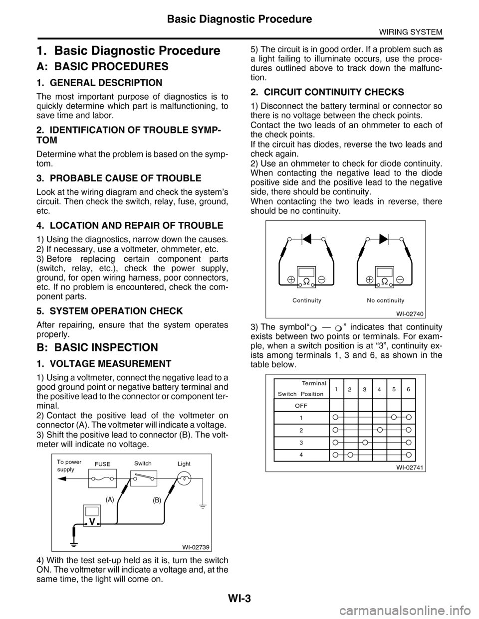
1) Using a voltmeter, connect the negative lead to a
good ground point or negative battery terminal and
the positive lead to the connector or component ter-
minal.
2) Contact the positive lead of the voltmeter on
connector (A). The voltmeter will indicate a voltage.
3) Shift the positive lead to connector (B). The volt-
meter will indicate no voltage.
4) With the test set-up held as it is, turn the switch
ON. The voltmeter will indicate a voltage and, at the
same time, the light will come on.
5) The circuit is in good order. If a problem such as
a light failing to illuminate occurs, use the proce-
dures outlined above to track down the malfunc-
tion.
2. CIRCUIT CONTINUITY CHECKS
1) Disconnect the battery terminal or connector so
there is no voltage between the check points.
Contact the two leads of an ohmmeter to each of
the check points.
If the circuit has diodes, reverse the two leads and
check again.
2) Use an ohmmeter to check for diode continuity.
When contacting the negative lead to the diode
positive side and the positive lead to the negative
side, there should be continuity.
When contacting the two leads in reverse, there
should be no continuity.
3) The symbol“ — ” indicates that continuity
exists between two points or terminals. For exam-
ple, when a switch position is at “3”, continuity ex-
ists among terminals 1, 3 and 6, as shown in the
table below.
WI-02739
To powerFUSEsupplySwitchLight
V
(A)(B)
WI-02740
Continuity No continuity
�