2009 SUBARU TRIBECA ac 25 procedure
[x] Cancel search: ac 25 procedurePage 1425 of 2453
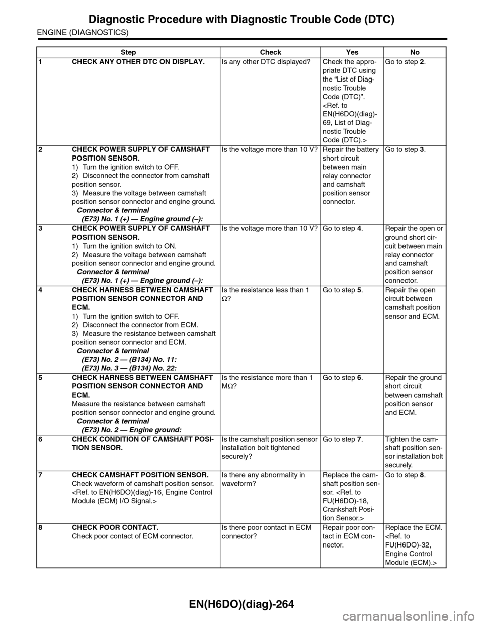
EN(H6DO)(diag)-264
Diagnostic Procedure with Diagnostic Trouble Code (DTC)
ENGINE (DIAGNOSTICS)
Step Check Yes No
1CHECK ANY OTHER DTC ON DISPLAY.Is any other DTC displayed? Check the appro-
priate DTC using
the “List of Diag-
nostic Trouble
Code (DTC)”.
69, List of Diag-
nostic Trouble
Code (DTC).>
Go to step 2.
2CHECK POWER SUPPLY OF CAMSHAFT
POSITION SENSOR.
1) Turn the ignition switch to OFF.
2) Disconnect the connector from camshaft
position sensor.
3) Measure the voltage between camshaft
position sensor connector and engine ground.
Connector & terminal
(E73) No. 1 (+) — Engine ground (–):
Is the voltage more than 10 V? Repair the battery
short circuit
between main
relay connector
and camshaft
position sensor
connector.
Go to step 3.
3CHECK POWER SUPPLY OF CAMSHAFT
POSITION SENSOR.
1) Turn the ignition switch to ON.
2) Measure the voltage between camshaft
position sensor connector and engine ground.
Connector & terminal
(E73) No. 1 (+) — Engine ground (–):
Is the voltage more than 10 V? Go to step 4.Repair the open or
ground short cir-
cuit between main
relay connector
and camshaft
position sensor
connector.
4CHECK HARNESS BETWEEN CAMSHAFT
POSITION SENSOR CONNECTOR AND
ECM.
1) Turn the ignition switch to OFF.
2) Disconnect the connector from ECM.
3) Measure the resistance between camshaft
position sensor connector and ECM.
Connector & terminal
(E73) No. 2 — (B134) No. 11:
(E73) No. 3 — (B134) No. 22:
Is the resistance less than 1
Ω?
Go to step 5.Repair the open
circuit between
camshaft position
sensor and ECM.
5CHECK HARNESS BETWEEN CAMSHAFT
POSITION SENSOR CONNECTOR AND
ECM.
Measure the resistance between camshaft
position sensor connector and engine ground.
Connector & terminal
(E73) No. 2 — Engine ground:
Is the resistance more than 1
MΩ?
Go to step 6.Repair the ground
short circuit
between camshaft
position sensor
and ECM.
6CHECK CONDITION OF CAMSHAFT POSI-
TION SENSOR.
Is the camshaft position sensor
installation bolt tightened
securely?
Go to step 7.Tighten the cam-
shaft position sen-
sor installation bolt
securely.
7CHECK CAMSHAFT POSITION SENSOR.
Check waveform of camshaft position sensor.
Is there any abnormality in
waveform?
Replace the cam-
shaft position sen-
sor.
Crankshaft Posi-
tion Sensor.>
Go to step 8.
8CHECK POOR CONTACT.
Check poor contact of ECM connector.
Is there poor contact in ECM
connector?
Repair poor con-
tact in ECM con-
nector.
Replace the ECM.
Engine Control
Module (ECM).>
Page 1426 of 2453
EN(H6DO)(diag)-265
Diagnostic Procedure with Diagnostic Trouble Code (DTC)
ENGINE (DIAGNOSTICS)
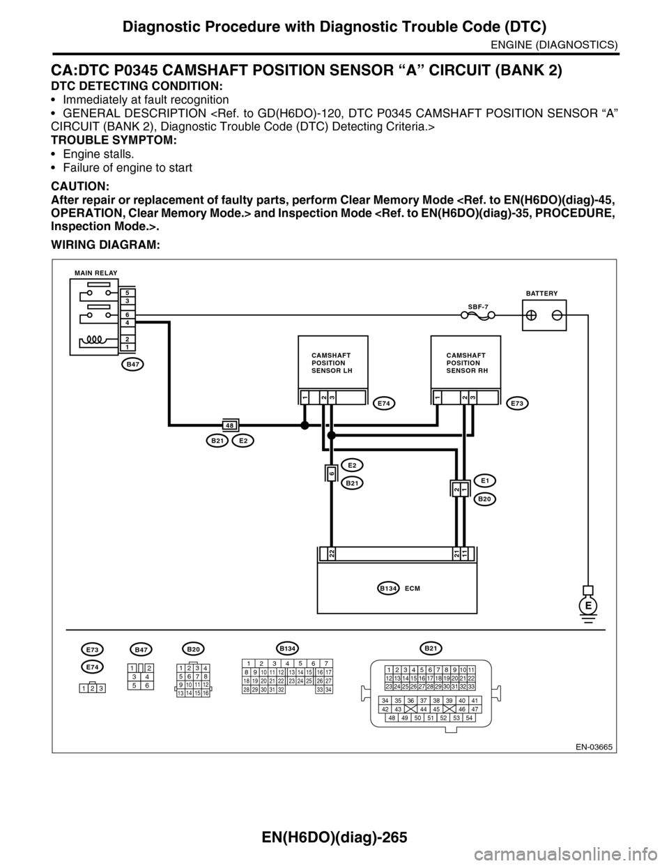
CA:DTC P0345 CAMSHAFT POSITION SENSOR “A” CIRCUIT (BANK 2)
DTC DETECTING CONDITION:
•Immediately at fault recognition
•GENERAL DESCRIPTION
TROUBLE SYMPTOM:
•Engine stalls.
•Failure of engine to start
CAUTION:
After repair or replacement of faulty parts, perform Clear Memory Mode
WIRING DIAGRAM:
EN-03665
B47
12
46
35
E
E2
B21
3
22
SBF-7
E74
E1
B20
2E73
B21E2
1
6
3
11
21
ECMB134
48
1
3412
56
B20
E74
B47
123
E73
BATTERY
CAMSHAFTPOSITIONSENSOR RH
CAMSHAFTPOSITIONSENSOR LH
MAIN RELAY
2
21
B21
123412131415567816171819910 1120212223 24 25 2627 28 29 3031 32 33
3534 37363938 41404342 4445 47464948 51505352 54
1234567891011 121314 15 16
B134
85610 11 12 13 14 157213416
3019 20 2228 29
91718252123 24323126 2733 34
Page 1427 of 2453
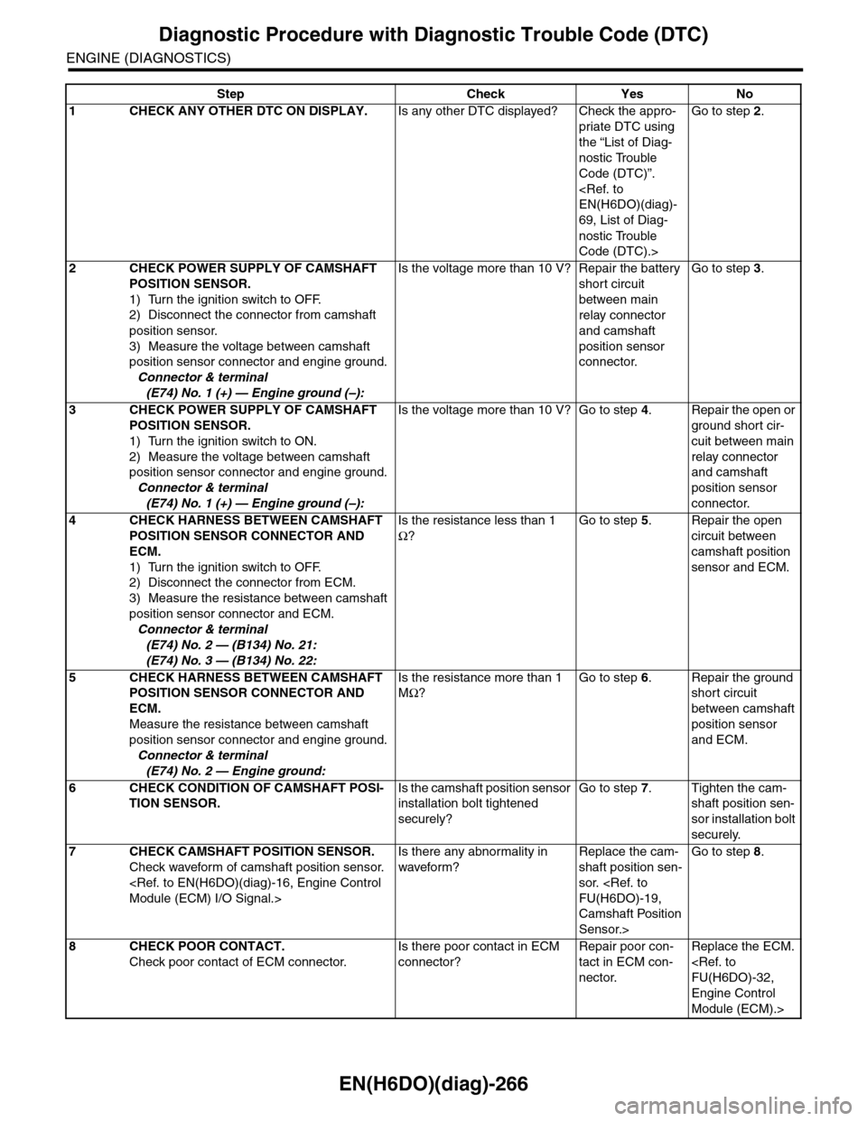
EN(H6DO)(diag)-266
Diagnostic Procedure with Diagnostic Trouble Code (DTC)
ENGINE (DIAGNOSTICS)
Step Check Yes No
1CHECK ANY OTHER DTC ON DISPLAY.Is any other DTC displayed? Check the appro-
priate DTC using
the “List of Diag-
nostic Trouble
Code (DTC)”.
69, List of Diag-
nostic Trouble
Code (DTC).>
Go to step 2.
2CHECK POWER SUPPLY OF CAMSHAFT
POSITION SENSOR.
1) Turn the ignition switch to OFF.
2) Disconnect the connector from camshaft
position sensor.
3) Measure the voltage between camshaft
position sensor connector and engine ground.
Connector & terminal
(E74) No. 1 (+) — Engine ground (–):
Is the voltage more than 10 V? Repair the battery
short circuit
between main
relay connector
and camshaft
position sensor
connector.
Go to step 3.
3CHECK POWER SUPPLY OF CAMSHAFT
POSITION SENSOR.
1) Turn the ignition switch to ON.
2) Measure the voltage between camshaft
position sensor connector and engine ground.
Connector & terminal
(E74) No. 1 (+) — Engine ground (–):
Is the voltage more than 10 V? Go to step 4.Repair the open or
ground short cir-
cuit between main
relay connector
and camshaft
position sensor
connector.
4CHECK HARNESS BETWEEN CAMSHAFT
POSITION SENSOR CONNECTOR AND
ECM.
1) Turn the ignition switch to OFF.
2) Disconnect the connector from ECM.
3) Measure the resistance between camshaft
position sensor connector and ECM.
Connector & terminal
(E74) No. 2 — (B134) No. 21:
(E74) No. 3 — (B134) No. 22:
Is the resistance less than 1
Ω?
Go to step 5.Repair the open
circuit between
camshaft position
sensor and ECM.
5CHECK HARNESS BETWEEN CAMSHAFT
POSITION SENSOR CONNECTOR AND
ECM.
Measure the resistance between camshaft
position sensor connector and engine ground.
Connector & terminal
(E74) No. 2 — Engine ground:
Is the resistance more than 1
MΩ?
Go to step 6.Repair the ground
short circuit
between camshaft
position sensor
and ECM.
6CHECK CONDITION OF CAMSHAFT POSI-
TION SENSOR.
Is the camshaft position sensor
installation bolt tightened
securely?
Go to step 7.Tighten the cam-
shaft position sen-
sor installation bolt
securely.
7CHECK CAMSHAFT POSITION SENSOR.
Check waveform of camshaft position sensor.
Is there any abnormality in
waveform?
Replace the cam-
shaft position sen-
sor.
Camshaft Position
Sensor.>
Go to step 8.
8CHECK POOR CONTACT.
Check poor contact of ECM connector.
Is there poor contact in ECM
connector?
Repair poor con-
tact in ECM con-
nector.
Replace the ECM.
Engine Control
Module (ECM).>
Page 1428 of 2453
EN(H6DO)(diag)-267
Diagnostic Procedure with Diagnostic Trouble Code (DTC)
ENGINE (DIAGNOSTICS)
CB:DTC P0420 CATALYST SYSTEM EFFICIENCY BELOW THRESHOLD (BANK 1)
DTC DETECTING CONDITION:
•Detected when two consecutive driving cycles with fault occur.
•GENERAL DESCRIPTION
TROUBLE SYMPTOM:
•Engine stalls.
•Idle mixture is out of specifications.
CAUTION:
After repair or replacement of faulty parts, perform Clear Memory Mode
Page 1429 of 2453
EN(H6DO)(diag)-268
Diagnostic Procedure with Diagnostic Trouble Code (DTC)
ENGINE (DIAGNOSTICS)
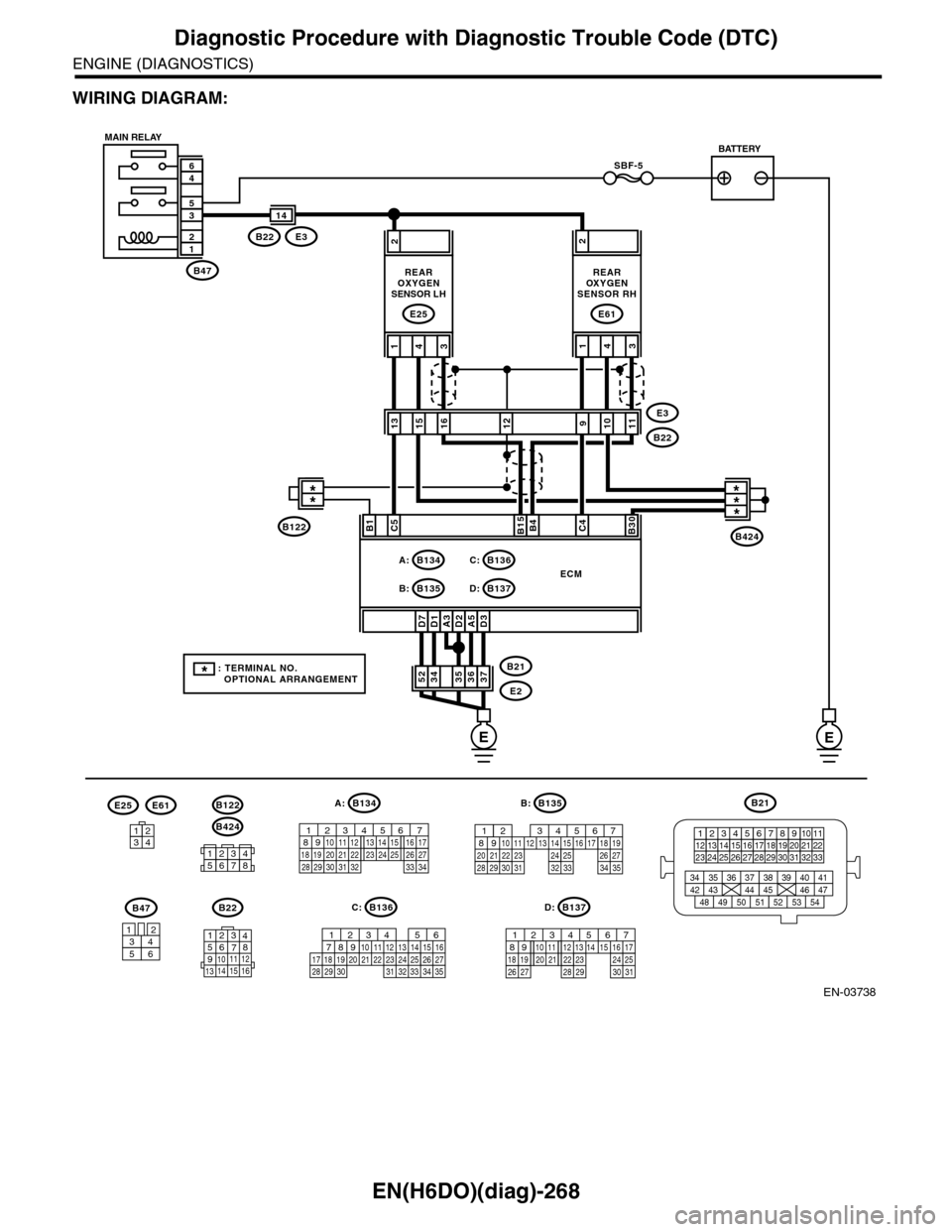
WIRING DIAGRAM:
EN-03738
SBF-5
B47
12
35
46
A3D7D1D2A5D3
2
373635363452B21
E2
ECM
C5B15B4C4B30
431
REAROXYGENSENSOR LH
E25
2
431
REAROXYGENSENSOR RH
E61
E3B22
14
1315E3
B221011129
B424
B47
3456
12
B21
123412131415567816171819910 1120212223 24 25 2627 28 29 3031 32 33
3534 37363938 41404342 4445 47464948 51505352 54
B135
567821943102422 23 2511 12 13 14 1526 2728
16 17 18 1920 2129 30 31 32 33 34 35
B:B134
56 7821943102422 23 2511 12 13 14 1526 2728
16 1718 19 20 2133 34293230 31
A:
16
B134A:
B135B:
B136C:
B137D:
B22
1234567891011 121314 15 16
B136
567821943102422 23 2511 12 13141526 2728
1617 18 19 20 2133 3429323031 35
C:B137
5678219431022 2311 12 13 14 1524 2526
16 1718 19 20 2127 28 29 30 31
D:
12345678
B424
B122
3412
E25E61
MAIN RELAYBATTERY
EE
* : TERMINAL NO. OPTIONAL ARRANGEMENT
***B1
**
B122
Page 1430 of 2453
EN(H6DO)(diag)-269
Diagnostic Procedure with Diagnostic Trouble Code (DTC)
ENGINE (DIAGNOSTICS)
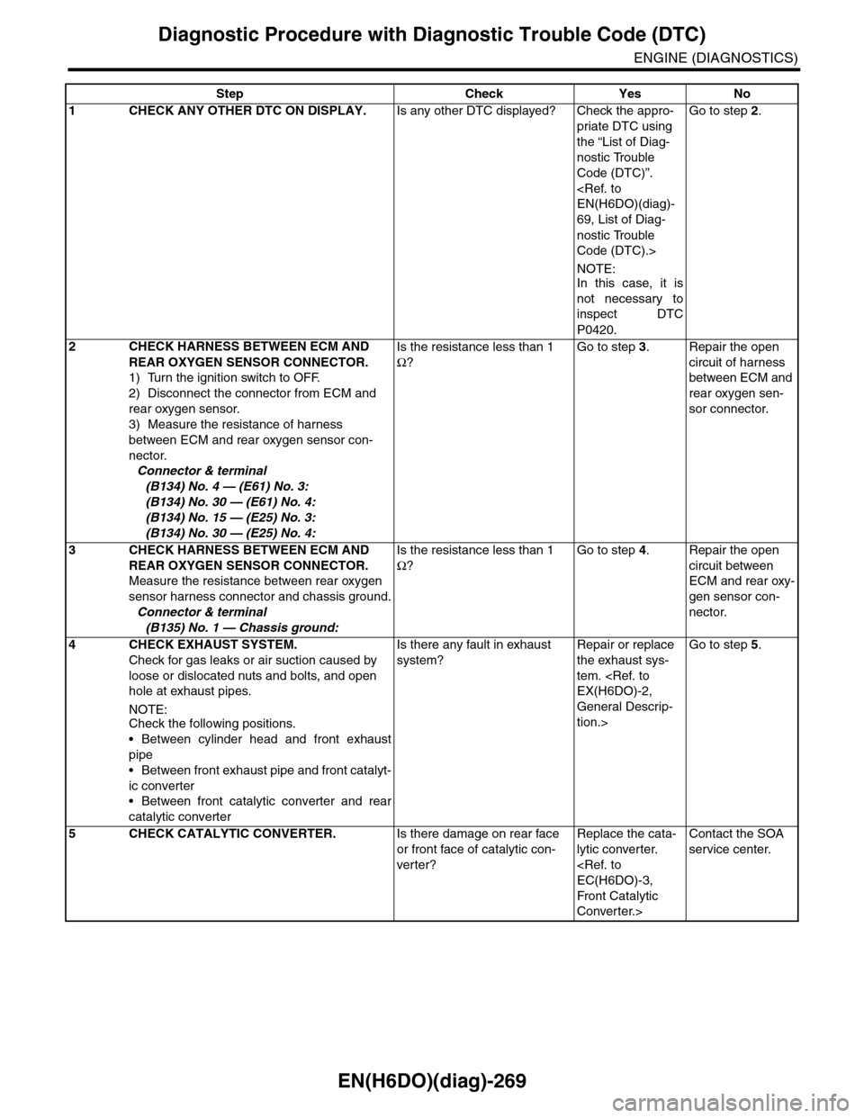
Step Check Yes No
1CHECK ANY OTHER DTC ON DISPLAY.Is any other DTC displayed? Check the appro-
priate DTC using
the “List of Diag-
nostic Trouble
Code (DTC)”.
69, List of Diag-
nostic Trouble
Code (DTC).>
NOTE:In this case, it is
not necessary to
inspect DTC
P0420.
Go to step 2.
2CHECK HARNESS BETWEEN ECM AND
REAR OXYGEN SENSOR CONNECTOR.
1) Turn the ignition switch to OFF.
2) Disconnect the connector from ECM and
rear oxygen sensor.
3) Measure the resistance of harness
between ECM and rear oxygen sensor con-
nector.
Connector & terminal
(B134) No. 4 — (E61) No. 3:
(B134) No. 30 — (E61) No. 4:
(B134) No. 15 — (E25) No. 3:
(B134) No. 30 — (E25) No. 4:
Is the resistance less than 1
Ω?
Go to step 3.Repair the open
circuit of harness
between ECM and
rear oxygen sen-
sor connector.
3CHECK HARNESS BETWEEN ECM AND
REAR OXYGEN SENSOR CONNECTOR.
Measure the resistance between rear oxygen
sensor harness connector and chassis ground.
Connector & terminal
(B135) No. 1 — Chassis ground:
Is the resistance less than 1
Ω?
Go to step 4.Repair the open
circuit between
ECM and rear oxy-
gen sensor con-
nector.
4 CHECK EXHAUST SYSTEM.
Check for gas leaks or air suction caused by
loose or dislocated nuts and bolts, and open
hole at exhaust pipes.
NOTE:Check the following positions.
•Between cylinder head and front exhaust
pipe
•Between front exhaust pipe and front catalyt-
ic converter
•Between front catalytic converter and rear
catalytic converter
Is there any fault in exhaust
system?
Repair or replace
the exhaust sys-
tem.
General Descrip-
tion.>
Go to step 5.
5CHECK CATALYTIC CONVERTER.Is there damage on rear face
or front face of catalytic con-
ver ter?
Replace the cata-
lytic converter.
Front Catalytic
Converter.>
Contact the SOA
service center.
Page 1431 of 2453
EN(H6DO)(diag)-270
Diagnostic Procedure with Diagnostic Trouble Code (DTC)
ENGINE (DIAGNOSTICS)
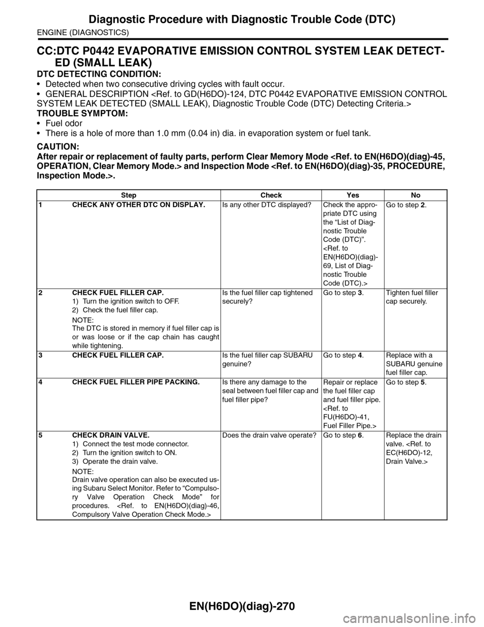
CC:DTC P0442 EVAPORATIVE EMISSION CONTROL SYSTEM LEAK DETECT-
ED (SMALL LEAK)
DTC DETECTING CONDITION:
•Detected when two consecutive driving cycles with fault occur.
•GENERAL DESCRIPTION
TROUBLE SYMPTOM:
•Fuel odor
•There is a hole of more than 1.0 mm (0.04 in) dia. in evaporation system or fuel tank.
CAUTION:
After repair or replacement of faulty parts, perform Clear Memory Mode
Step Check Yes No
1CHECK ANY OTHER DTC ON DISPLAY.Is any other DTC displayed? Check the appro-
priate DTC using
the “List of Diag-
nostic Trouble
Code (DTC)”.
69, List of Diag-
nostic Trouble
Code (DTC).>
Go to step 2.
2CHECK FUEL FILLER CAP.
1) Turn the ignition switch to OFF.
2) Check the fuel filler cap.
NOTE:
The DTC is stored in memory if fuel filler cap is
or was loose or if the cap chain has caught
while tightening.
Is the fuel filler cap tightened
securely?
Go to step 3.Tighten fuel filler
cap securely.
3CHECK FUEL FILLER CAP.Is the fuel filler cap SUBARU
genuine?
Go to step 4.Replace with a
SUBARU genuine
fuel filler cap.
4CHECK FUEL FILLER PIPE PACKING.Is there any damage to the
seal between fuel filler cap and
fuel filler pipe?
Repair or replace
the fuel filler cap
and fuel filler pipe.
Fuel Filler Pipe.>
Go to step 5.
5CHECK DRAIN VALVE.
1) Connect the test mode connector.
2) Turn the ignition switch to ON.
3) Operate the drain valve.
NOTE:
Drain valve operation can also be executed us-
ing Subaru Select Monitor. Refer to “Compulso-
ry Valve Operation Check Mode” for
procedures.
Does the drain valve operate? Go to step 6.Replace the drain
valve.
Drain Valve.>
Page 1432 of 2453
EN(H6DO)(diag)-271
Diagnostic Procedure with Diagnostic Trouble Code (DTC)
ENGINE (DIAGNOSTICS)
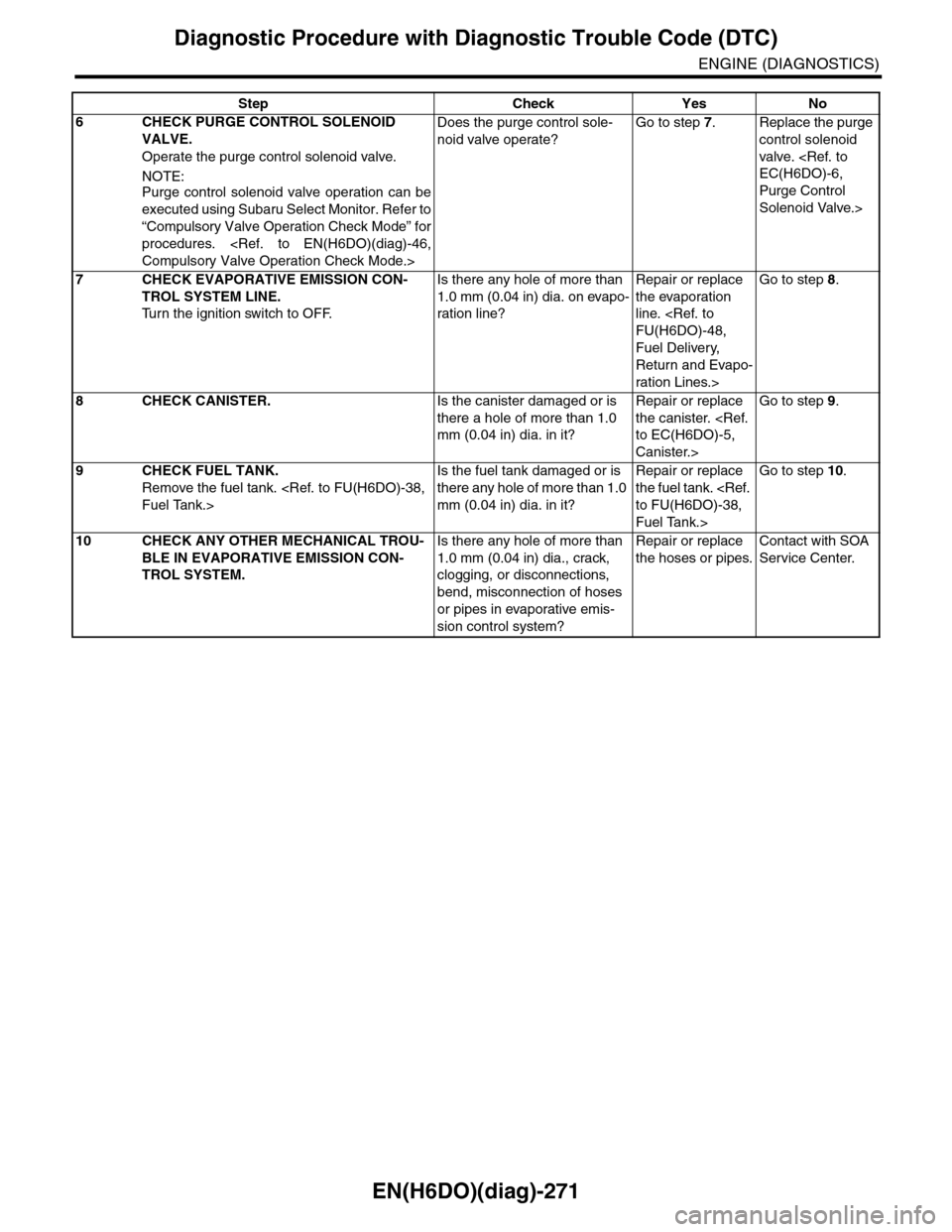
6CHECK PURGE CONTROL SOLENOID
VALVE.
Operate the purge control solenoid valve.
NOTE:Purge control solenoid valve operation can be
executed using Subaru Select Monitor. Refer to
“Compulsory Valve Operation Check Mode” for
procedures.
Does the purge control sole-
noid valve operate?
Go to step 7.Replace the purge
control solenoid
valve.
Purge Control
Solenoid Valve.>
7CHECK EVAPORATIVE EMISSION CON-
TROL SYSTEM LINE.
Tu r n t h e i g n i t i o n s w i t c h t o O F F.
Is there any hole of more than
1.0 mm (0.04 in) dia. on evapo-
ration line?
Repair or replace
the evaporation
line.
Fuel Delivery,
Return and Evapo-
ration Lines.>
Go to step 8.
8CHECK CANISTER.Is the canister damaged or is
there a hole of more than 1.0
mm (0.04 in) dia. in it?
Repair or replace
the canister.
Canister.>
Go to step 9.
9CHECK FUEL TANK.
Remove the fuel tank.
Is the fuel tank damaged or is
there any hole of more than 1.0
mm (0.04 in) dia. in it?
Repair or replace
the fuel tank.
Fuel Tank.>
Go to step 10.
10 CHECK ANY OTHER MECHANICAL TROU-
BLE IN EVAPORATIVE EMISSION CON-
TROL SYSTEM.
Is there any hole of more than
1.0 mm (0.04 in) dia., crack,
clogging, or disconnections,
bend, misconnection of hoses
or pipes in evaporative emis-
sion control system?
Repair or replace
the hoses or pipes.
Contact with SOA
Service Center.
Step Check Yes No