2009 SUBARU TRIBECA torque
[x] Cancel search: torquePage 2226 of 2453
5AT(diag)-109
Diagnostic Procedure with Diagnostic Trouble Code (DTC)
AUTOMATIC TRANSMISSION (DIAGNOSTICS)
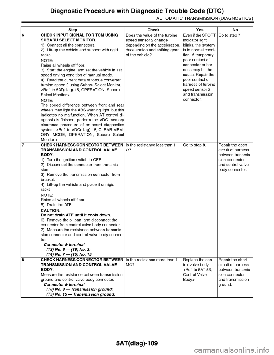
6CHECK INPUT SIGNAL FOR TCM USING
SUBARU SELECT MONITOR.
1) Connect all the connectors.
2) Lift-up the vehicle and support with rigid
racks.
NOTE:
Raise all wheels off floor.
3) Start the engine, and set the vehicle in 1st
speed driving condition of manual mode.
4) Read the current data of torque converter
turbine speed 2 using Subaru Select Monitor.
NOTE:The speed difference between front and rear
wheels may light the ABS warning light, but this
indicates no malfunction. When AT control di-
agnosis is finished, perform the VDC memory
clearance procedure of on-board diagnostics
system.
Monitor.>
Does the value of the turbine
speed sensor 2 change
depending on the acceleration,
deceleration and shifting gear
of the vehicle?
Even if the SPORT
indicator light
blinks, the system
is in normal condi-
tion. A temporary
poor contact of
connector or har-
ness may be the
cause. Repair the
poor contact of
harness of turbine
speed sensor 2
and transmission
connector.
Go to step 7.
7CHECK HARNESS CONNECTOR BETWEEN
TRANSMISSION AND CONTROL VALVE
BODY.
1) Turn the ignition switch to OFF.
2) Disconnect the connector from transmis-
sion.
3) Remove the transmission connector from
bracket.
4) Lift-up the vehicle and place it on rigid
racks.
NOTE:
Raise all wheels off floor.
5) Drain the ATF.
CAUTION:Do not drain ATF until it cools down.
6) Remove the oil pan, and disconnect the
connector from control valve body connector.
7) Measure the resistance between transmis-
sion connector and control valve body connec-
tor.
Connector & terminal
(T3) No. 6 — (T6) No. 3:
(T4) No. 7 — (T5) No. 15:
Is the resistance less than 1
Ω?
Go to step 8.Repair the open
circuit of harness
between transmis-
sion connector
and control valve
body connector.
8CHECK HARNESS CONNECTOR BETWEEN
TRANSMISSION AND CONTROL VALVE
BODY.
Measure the resistance between transmission
ground and control valve body connector.
Connector & terminal
(T6) No. 3 — Transmission ground:
(T5) No. 15 — Transmission ground:
Is the resistance more than 1
MΩ?
Replace the con-
trol valve body.
Body.>
Repair the short
circuit of harness
between transmis-
sion connector
and transmission
ground.
Step Check Yes No
Page 2255 of 2453
CS-3
General Description
CONTROL SYSTEMS
B: PREPARATION TOOL
1. SPECIAL TOOL
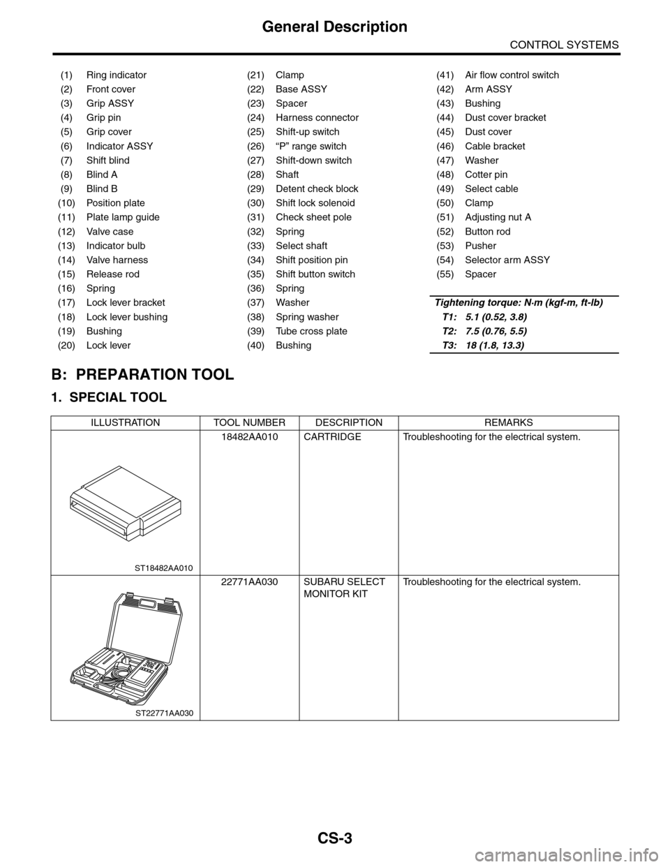
(1) Ring indicator (21) Clamp (41) Air flow control switch
(2) Front cover (22) Base ASSY (42) Arm ASSY
(3) Grip ASSY (23) Spacer (43) Bushing
(4) Grip pin (24) Harness connector (44) Dust cover bracket
(5) Grip cover (25) Shift-up switch (45) Dust cover
(6) Indicator ASSY (26) “P” range switch (46) Cable bracket
(7) Shift blind (27) Shift-down switch (47) Washer
(8) Blind A (28) Shaft (48) Cotter pin
(9) Blind B (29) Detent check block (49) Select cable
(10) Position plate (30) Shift lock solenoid (50) Clamp
(11) Plate lamp guide (31) Check sheet pole (51) Adjusting nut A
(12) Valve case (32) Spring (52) Button rod
(13) Indicator bulb (33) Select shaft (53) Pusher
(14) Valve harness (34) Shift position pin (54) Selector arm ASSY
(15) Release rod (35) Shift button switch (55) Spacer
(16) Spring (36) Spring
(17) Lock lever bracket (37) WasherTightening torque: N·m (kgf-m, ft-lb)
(18) Lock lever bushing (38) Spring washerT1: 5.1 (0.52, 3.8)
(19) Bushing (39) Tube cross plateT2: 7.5 (0.76, 5.5)
(20) Lock lever (40) BushingT3: 18 (1.8, 13.3)
ILLUSTRATION TOOL NUMBER DESCRIPTION REMARKS
18482AA010 CARTRIDGE Troubleshooting for the electrical system.
22771AA030 SUBARU SELECT
MONITOR KIT
Tr o u b l e s h o o t i n g f o r t h e e l e c t r i c a l s y s t e m .
ST18482AA010
ST22771AA030
Page 2256 of 2453
CS-4
General Description
CONTROL SYSTEMS
C: CAUTION
•Wear work clothing, including a cap, protective
goggles and protective shoes during operation.
•Remove contamination including dirt and corro-
sion before removal, installation or disassembly.
•Keep the disassembled parts in order and pro-
tect them from dust and dirt.
•Before removal, installation or disassembly, be
sure to clarify the failure. Avoid unnecessary re-
moval, installation, disassembly and replacement.
•Use SUBARU genuine fluid, grease etc. or
equivalent. Do not mix fluid, grease, etc. with that of
another grade or from other manufacturers.
•Be sure to tighten fasteners including bolts and
nuts to the specified torque.
•Place shop jacks or rigid racks at the specified
points.
•Apply grease onto sliding or revolution surfaces
before installation.
•Before installing O-rings or snap rings, apply suf-
ficient amount of fluid to avoid damage and defor-
mation.
•Before securing a part in a vise, place cushioning
material such as wood blocks, aluminum plate or
cloth between the part and the vise.
•Before disconnecting electrical connectors, be
sure to disconnect the negative terminal from bat-
tery.
Page 2271 of 2453
CS-19
Select Lever
CONTROL SYSTEMS
3. Select Lever
A: REMOVAL
1) Set the vehicle on a lift.
2) Disconnect the ground cable from battery.
3) Shift the select lever to “N” range.
4) Lift–up the vehicle.
5) Remove the rear exhaust pipe and muffler.
6) Remove the heat shield cover.
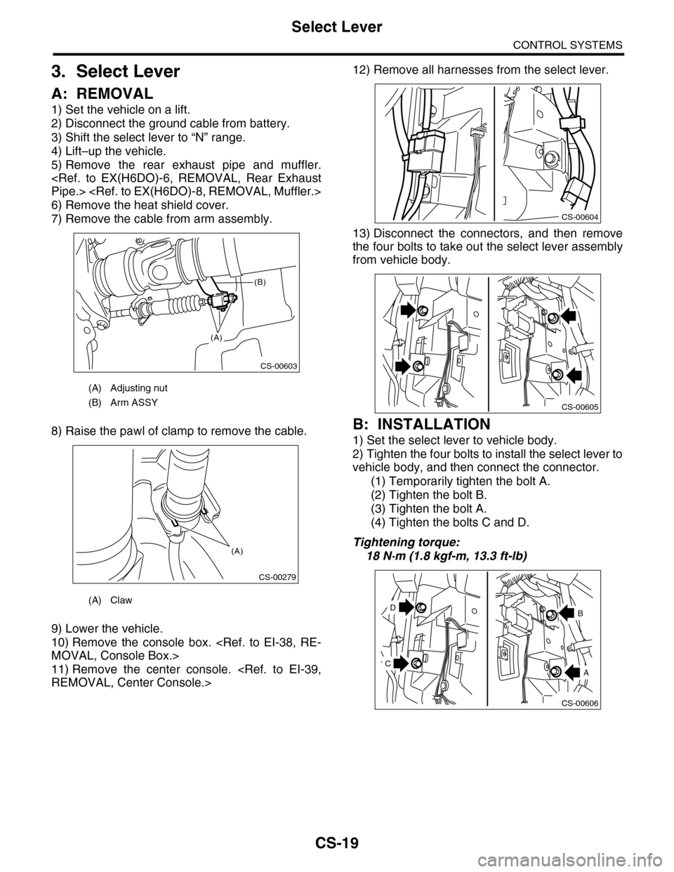
7) Remove the cable from arm assembly.
8) Raise the pawl of clamp to remove the cable.
9) Lower the vehicle.
10) Remove the console box.
11) Remove the center console.
12) Remove all harnesses from the select lever.
13) Disconnect the connectors, and then remove
the four bolts to take out the select lever assembly
from vehicle body.
B: INSTALLATION
1) Set the select lever to vehicle body.
2) Tighten the four bolts to install the select lever to
vehicle body, and then connect the connector.
(1) Temporarily tighten the bolt A.
(2) Tighten the bolt B.
(3) Tighten the bolt A.
(4) Tighten the bolts C and D.
Tightening torque:
18 N·m (1.8 kgf-m, 13.3 ft-lb)
(A) Adjusting nut
(B) Arm ASSY
(A) Claw
CS-00603
(A)
(B)
CS-00279
(A)
CS-00604
CS-00605
CS-00606
D
A
B
C
Page 2277 of 2453
![SUBARU TRIBECA 2009 1.G Service Workshop Manual CS-25
Select Lever
CONTROL SYSTEMS
D: ASSEMBLY
1) Clean all the parts before assembly.
2) Apply grease [Multemp AC-D, and SH-W or
equivalent] to each part. <Ref. to CS-2, AT SE-
LECT LE SUBARU TRIBECA 2009 1.G Service Workshop Manual CS-25
Select Lever
CONTROL SYSTEMS
D: ASSEMBLY
1) Clean all the parts before assembly.
2) Apply grease [Multemp AC-D, and SH-W or
equivalent] to each part. <Ref. to CS-2, AT SE-
LECT LE](/manual-img/17/7322/w960_7322-2276.png)
CS-25
Select Lever
CONTROL SYSTEMS
D: ASSEMBLY
1) Clean all the parts before assembly.
2) Apply grease [Multemp AC-D, and SH-W or
equivalent] to each part.
tion.>
3) Assemble in the reverse order of disassembly.
NOTE:
•Refer to “COMPONENT” for each tightening
torque.
•When pressing in the shift position pin, insert
from the left side of the vehicle.
•Affix the harness of the shift button switch and
the mode change switch at the marked positions.
•Connect the terminals of all switches to the re-
spective connectors.
4) After completing installation, shift the select le-
ver from the “P” range to the “D” range, then check
whether or not the selection indicator in the combi-
nation meter and the select lever position matches.
Also check whether the pointer and position mark
matches, and what the operating force is.
E: INSPECTION
1) Inspect the removed parts by comparing with
new ones for deformation, damage and wear. Re-
pair or replace if defective.
2) Confirm the select lever operating condition be-
fore assembly. Normal if it operates smoothly. CS-00641
(A) Mode change switch (color code: Yellow)
(B) Shift button switch (color code: Brown)
(C) Mode change switch and shift button switch
ground (color code: White)
(D) Shift up switch (color code: Green)
(E) Shift up switch (color code: Gray)
(F) Shift up/down switch ground (color code: Blue)
(G) “P” range switch (wire color: Red)
(H) Shift lock solenoid (color code: Blue)
(I) Shift lock solenoid (color code: Black)
(J) Indicator lamp (color code: Blue)
CS-00642
5432112 11 10 9876
(J)
(J)(F)(E)(D)(A)(B)(C)
(H) (G)(I)
Page 2278 of 2453
CS-26
Select Cable
CONTROL SYSTEMS
4. Select Cable
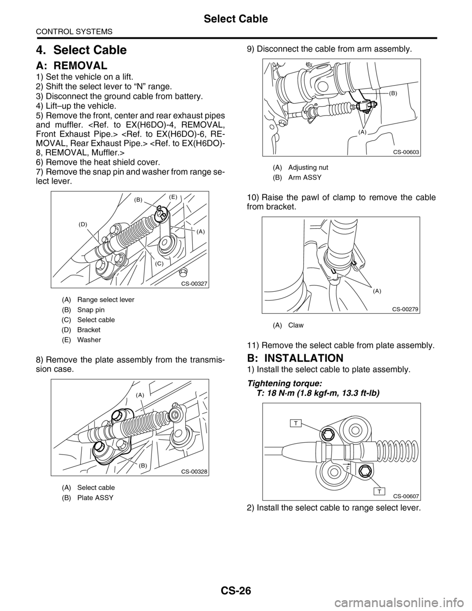
A: REMOVAL
1) Set the vehicle on a lift.
2) Shift the select lever to “N” range.
3) Disconnect the ground cable from battery.
4) Lift–up the vehicle.
5) Remove the front, center and rear exhaust pipes
and muffler.
6) Remove the heat shield cover.
7) Remove the snap pin and washer from range se-
lect lever.
8) Remove the plate assembly from the transmis-
sion case.
9) Disconnect the cable from arm assembly.
10) Raise the pawl of clamp to remove the cable
from bracket.
11) Remove the select cable from plate assembly.
B: INSTALLATION
1) Install the select cable to plate assembly.
Tightening torque:
T: 18 N·m (1.8 kgf-m, 13.3 ft-lb)
2) Install the select cable to range select lever.
(A) Range select lever
(B) Snap pin
(C) Select cable
(D) Bracket
(E) Washer
(A) Select cable
(B) Plate ASSY
CS-00327
(B)
(D)
(C)
(E)
(A)
(A)
(B)CS-00328
(A) Adjusting nut
(B) Arm ASSY
(A) Claw
CS-00603
(A)
(B)
CS-00279
(A)
CS-00607
T
T
Page 2279 of 2453
CS-27
Select Cable
CONTROL SYSTEMS
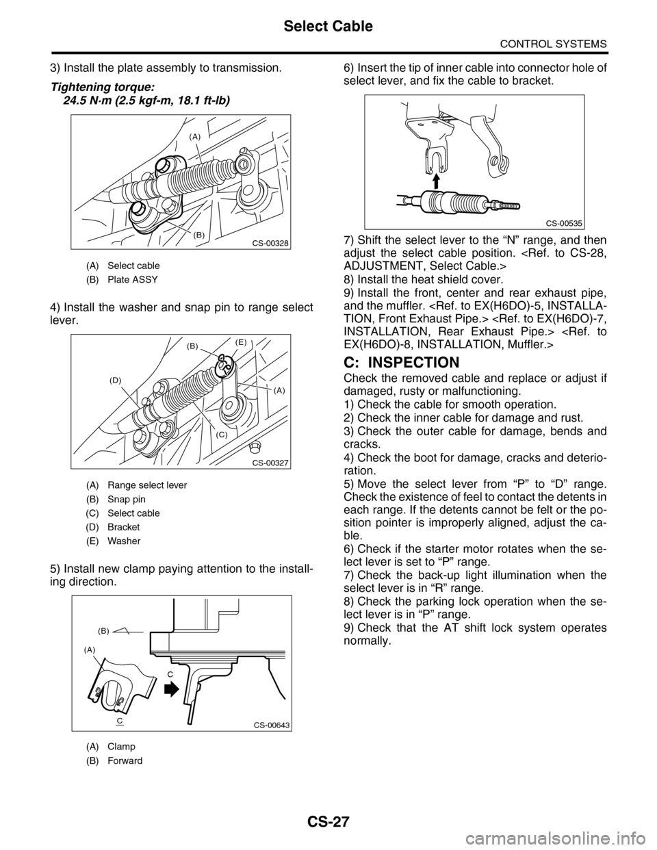
3) Install the plate assembly to transmission.
Tightening torque:
24.5 N·m (2.5 kgf-m, 18.1 ft-lb)
4) Install the washer and snap pin to range select
lever.
5) Install new clamp paying attention to the install-
ing direction.
6) Insert the tip of inner cable into connector hole of
select lever, and fix the cable to bracket.
7) Shift the select lever to the “N” range, and then
adjust the select cable position.
8) Install the heat shield cover.
9) Install the front, center and rear exhaust pipe,
and the muffler.
C: INSPECTION
Check the removed cable and replace or adjust if
damaged, rusty or malfunctioning.
1) Check the cable for smooth operation.
2) Check the inner cable for damage and rust.
3) Check the outer cable for damage, bends and
cracks.
4) Check the boot for damage, cracks and deterio-
ration.
5) Move the select lever from “P” to “D” range.
Check the existence of feel to contact the detents in
each range. If the detents cannot be felt or the po-
sition pointer is improperly aligned, adjust the ca-
ble.
6) Check if the starter motor rotates when the se-
lect lever is set to “P” range.
7) Check the back-up light illumination when the
select lever is in “R” range.
8) Check the parking lock operation when the se-
lect lever is in “P” range.
9) Check that the AT shift lock system operates
normally.
(A) Select cable
(B) Plate ASSY
(A) Range select lever
(B) Snap pin
(C) Select cable
(D) Bracket
(E) Washer
(A) Clamp
(B) Forward
(A)
(B)CS-00328
CS-00327
(B)
(D)
(C)
(E)
(A)
CS-00643
(A)
(B)
C
C
CS-00535
Page 2280 of 2453
CS-28
Select Cable
CONTROL SYSTEMS
D: ADJUSTMENT
1) Shift the select lever to “N” range.
2) Remove the rear exhaust pipe and muffler.
3) Remove the heat shield cover.
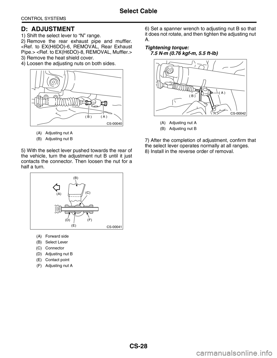
4) Loosen the adjusting nuts on both sides.
5) With the select lever pushed towards the rear of
the vehicle, turn the adjustment nut B until it just
contacts the connector. Then loosen the nut for a
half a turn.
6) Set a spanner wrench to adjusting nut B so that
it does not rotate, and then tighten the adjusting nut
A.
Tightening torque:
7.5 N·m (0.76 kgf-m, 5.5 ft-lb)
7) After the completion of adjustment, confirm that
the select lever operates normally at all ranges.
8) Install in the reverse order of removal.
(A) Adjusting nut A
(B) Adjusting nut B
(A) Forward side
(B) Select Lever
(C) Connector
(D) Adjusting nut B
(E) Contact point
(F) Adjusting nut A
CS-00040
( A )( B )
CS-00041
(A)
(B)
(C)
(D)
(E)
(F)
(A) Adjusting nut A
(B) Adjusting nut B
CS-00042
( A )( B )