Page 2398 of 2453
WI-114
Navigation System
WIRING SYSTEM
WI-08117
NAVI-03NAVI-03
G
B1
i131AUDIO MODULE
1
RY
B2
2
BrW
B3
3
W
B6
6
GOr
B7
7
WL
B10
10
R
B11
11
L
B12
12
P
B17
17
LW
B18
18
YB
B19
19
BrY
GRYBrWWGOrWLRLPLWYBBrYYBr
B20
YBr
B9B8
2098
i112
123456
i112
Y
YJOINT CONNECTOR1*
Br2*
Br2*
1*
i120TV MONITORB:
:TERMINAL NO. OPTIONAL ARRANGEMENT AMONG 1, 2 AND 3
:TERMINAL NO. OPTIONAL ARRANGEMENT AMONG 4, 5 AND 6
1*
2*
i131
123 8910413 14 15 16567111217181920
i120B:
TWISTED PAIR LINE
TWISTED PAIR LINE
(BLACK)
(BLACK)
Page 2399 of 2453
WI-115
Navigation System
WIRING SYSTEM
WI-08118
NAVI-04NAVI-04
i118NAVIGATION SWITCH
W
1
WB
2
WR
3
WG
4
WL
5
BW
6
BR
7
BY
WWBWRWGWLBWBRBY
8
i121NAVIGATION SWITCH
12345678
i121
i118
12345678
(BLACK)
(BLACK)
Page 2443 of 2453

WI-159
Instrument Panel Wiring Harness
WIRING SYSTEM
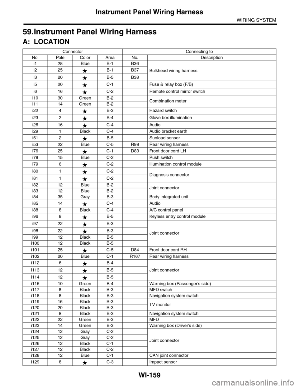
59.Instrument Panel Wiring Harness
A: LOCATION
Connector Connecting to
No. Pole Color Area No. Description
i1 28 Blue B-1 B36
Bulkhead wiring harnessi2 25 B-1 B37
i3 20 B-5 B38
i5 20 C-1 Fuse & relay box (F/B)
i6 16 C-2 Remote control mirror switch
i10 30 Green B-2Combination meteri11 14 Green B-2
i22 4 B-3 Hazard switch
i23 2 B-4 Glove box illumination
i26 16 C-4 Audio
i29 1 Black C-4 Audio bracket earth
i51 2 B-5 Sunload sensor
i53 22 Blue C-5 R98 Rear wiring harness
i76 25 C-1 D83 Front door cord LH
i78 15 Blue C-2 Push switch
i79 6 C-2 Illumination control module
i80 1 C-2Diagnosis connectori81 1 C-2
i82 12 Blue B-2Joint connectori83 12 Blue B-2
i84 35 Gray B-3 Body integrated unit
i85 14 C-4 Audio
i88 8 Black C-4 A/C control panel
i96 8 B-5 Keyless entry control module
i97 22 B-3
Joint connectori98 22 B-3
i99 12 Black B-5
i100 12 Black B-5
i101 25 C-5 D84 Front door cord RH
i102 20 Blue C-1 R167 Rear wiring harness
i112 6 B-4
Joint connectori113 12 B-5
i114 12 B-5
i116 10 Green B-4 Warning box (Passenger’s side)
i117 8 Black B-3 MFD switch
i118 8 Black B-3 Navigation system switch
i119 16 Black B-3TV monitori120 20 Black B-3
i121 8 Black B-3 Navigation system switch
i122 22 Green B-3 MFD
i123 14 Green B-3 Warning box (Driver’s side)
i124 12 Gray C-2
Joint connectori125 12 Gray C-2
i126 12 Black C-1
i127 12 Black C-2
i128 12 Blue C-1 CAN joint connector
i129 8 C-3 Impact sensor
Page 2448 of 2453

WI-164
Rear Wiring Harness
WIRING SYSTEM
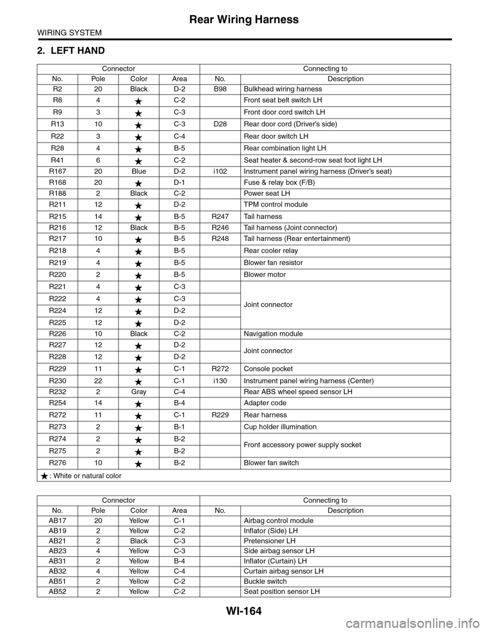
2. LEFT HAND
Connector Connecting to
No. Pole Color Area No. Description
R2 20 Black D-2 B98 Bulkhead wiring harness
R8 4 C-2 Front seat belt switch LH
R9 3 C-3 Front door cord switch LH
R13 10 C-3 D28 Rear door cord (Driver’s side)
R22 3 C-4 Rear door switch LH
R28 4 B-5 Rear combination light LH
R41 6 C-2 Seat heater & second-row seat foot light LH
R167 20 Blue D-2 i102 Instrument panel wiring harness (Driver’s seat)
R168 20 D-1 Fuse & relay box (F/B)
R188 2 Black C-2 Power seat LH
R211 12 D-2 TPM control module
R215 14 B-5 R247 Tail harness
R216 12 Black B-5 R246 Tail harness (Joint connector)
R217 10 B-5 R248 Tail harness (Rear entertainment)
R218 4 B-5 Rear cooler relay
R219 4 B-5 Blower fan resistor
R220 2 B-5 Blower motor
R221 4 C-3
Joint connectorR222 4 C-3
R224 12 D-2
R225 12 D-2
R226 10 Black C-2 Navigation module
R227 12 D-2Joint connectorR228 12 D-2
R229 11 C-1 R272 Console pocket
R230 22 C-1 i130 Instrument panel wiring harness (Center)
R232 2 Gray C-4 Rear ABS wheel speed sensor LH
R254 14 B-4 Adapter code
R272 11 C-1 R229 Rear harness
R273 2 B-1 Cup holder illumination
R274 2 B-2Fr o nt a cc es so r y p ower s up pl y s ocke tR275 2 B-2
R276 10 B-2 Blower fan switch
: White or natural color
Connector Connecting to
No. Pole Color Area No. Description
AB17 20 Yellow C-1 Airbag control module
AB19 2 Yellow C-2 Inflator (Side) LH
AB21 2 Black C-3 Pretensioner LH
AB23 4 Yellow C-3 Side airbag sensor LH
AB31 2 Yellow B-4 Inflator (Curtain) LH
AB32 4 Yellow C-4 Curtain airbag sensor LH
AB51 2 Yellow C-2 Buckle switch
AB52 2 Yellow C-2 Seat position sensor LH