Page 972 of 2453

TPM(diag)-22
Tire Pressure Warning Light/Trouble Indicator Light Illumination Pattern (DTC)
TIRE PRESSURE MONITORING SYSTEM (DIAGNOSTICS)
C: TIRE PRESSURE WARNING LIGHT DOES NOT COME OFF
DETECTING CONDITION:
•Defective combination meter
•Defective harness
•Tires pressure drop
•Transmitter ID not registered
TROUBLE SYMPTOM:
Tire pressure warning light does not go off after engine starts.
WIRING DIAGRAM:
TPM00019
TO POWER SUPPLY CIRCUIT
FB-36 F/B FUSE NO.5(IG)
26
COMBINATIONMETERA:i10
A3
A10
TIRE INFLATION PRESSURE WARNINGLIGHT
FB-17F/B FUSE NO. 7 (B)
i102
R167
R211
FB-48F/B FUSE NO. 4 (IG)
A4
INVERTING CIRCUIT
15
5
9
TPM CONTROL MODULE
i102
1238910411 12 1314 15 16567
A:i10
12345 678910111219 20 2113 14 15 161718 22
R211
123456789101112
Step Check Yes No
1CHECK DIAGNOSTIC TROUBLE CODE
(DTC)
Connect Subaru Select Monitor, read Diagnos-
tic Trouble Code.
DIAGNOSTIC TROUBLE CODE (DTC),
OPERATION, Subaru Select Monitor.>
Is DTC displayed? Perform the diag-
nosis according to
DTC.
TPM(diag)-26, List
of Diagnostic Trou-
ble Code (DTC).>
Go to step 2.
Page 974 of 2453

TPM(diag)-24
Tire Pressure Warning Light/Trouble Indicator Light Illumination Pattern (DTC)
TIRE PRESSURE MONITORING SYSTEM (DIAGNOSTICS)
D: TIRE PRESSURE WARNING LIGHT IS BLINKING
DETECTING CONDITION:
•Tire pressure monitoring control module is faulty.
•Defective harness
•Transmitter is faulty.
TROUBLE SYMPTOM:
Tire pressure warning light blinks continuously after engine starting.
WIRING DIAGRAM:
TPM00019
TO POWER SUPPLY CIRCUIT
FB-36 F/B FUSE NO.5(IG)
26
COMBINATIONMETERA:i10
A3
A10
TIRE INFLATION PRESSURE WARNINGLIGHT
FB-17F/B FUSE NO. 7 (B)
i102
R167
R211
FB-48F/B FUSE NO. 4 (IG)
A4
INVERTING CIRCUIT
15
5
9
TPM CONTROL MODULE
i102
1238910411 12 1314 15 16567
A:i10
12345 678910111219 20 2113 14 15 161718 22
R211
123456789101112
Step Check Yes No
1CHECK DIAGNOSTIC TROUBLE CODE
(DTC)
Connect Subaru Select Monitor, read Diagnos-
tic Trouble Code.
DIAGNOSTIC TROUBLE CODE (DTC),
OPERATION, Subaru Select Monitor.>
Is diagnostics code (DTC) dis-
played?
Pe r for m t h e d ia g -
nosis according to
DTC.
TPM(diag)-26, List
of Diagnostic Trou-
ble Code (DTC).>
Go to step 2.
Page 984 of 2453
TPM(diag)-34
Diagnostic Procedure with Diagnostic Trouble Code (DTC)
TIRE PRESSURE MONITORING SYSTEM (DIAGNOSTICS)
U: DTC 61 VEHICLE SPEED IS ABNORMAL
DTC DETECTING CONDITION:
Vehicle speed function codes were received from the transmitter, but the vehicle speed signal was not input
to the module.
TROUBLE SYMPTOM:
Tire pressure warning light blinks.
WIRING DIAGRAM:
TPM00020
4
COMBINATIONMETER
A:i10
A1
A27
R2
R7
R211
A2
I/F
8
9
TPM CONTROL MODULE
i102
1238910411 12 1314 15 16567
A:i10
12345 678910111219 20 2113 14 15 161718 22
R211
16
B310
MICROCOMPUTER
SPEEDOMETER
FB-17 F/B FUSE NO. 7(B)
TO POWER SUPPLYCIRCUIT
i3B38
B38
1234 5678910 11 12 13 14 15 16 17 18 19 20
36
VDC CONTROL MODULE
123456789101112
B310
12345678910 11 12 13 14
15 16 17 18 19 2021 22 23 24 25 26 27 2829 30 31 32 33 3435 36 37 38 39403940
27 283940
Page 1126 of 2453
CO(H6DO)-7
Radiator Fan System
COOLING
2. Radiator Fan System
A: WIRING DIAGRAM
CO-02209
RADIATOR FANCONTROL UNIT
132
B136
ECM
16
F109
F106
7
B360
2918
F106
123
B7
E
SBF-6MAIN SBF
NO.2
NO.26
B143B:
F36E:
E6
3127456
F36E:B143
123456712131415161718
B:
8191192010
EM
SUB FAN MOTORMAIN FAN MOTOR
THROUGH JOINTCONNECTOR
MAIN FANRELAY 1
MAIN FUSEBOX (M/B)
IGNITIONSWITCH
F17F11112
M
12
F111
F17
12
F109
3412 8910 1112 13 14 15 16 17 18 19 20 21 22 23 24567
B136
16101112131415252430
9871718192028212223293231
123456
2726333435
B360
12345678910111213141516
Page 2210 of 2453
5AT(diag)-93
Diagnostic Procedure with Diagnostic Trouble Code (DTC)
AUTOMATIC TRANSMISSION (DIAGNOSTICS)
AD:DTC P0882 TCM POWER INPUT SIGNAL LOW
DTC DETECTING CONDITION:
Malfunction of PVIGN power supply relay or open, short circuit of PVIGN power supply circuit.
TROUBLE SYMPTOM:
Gear is not changed.
WIRING DIAGRAM:
AT-03294
8710
B54
B357
TCM
B54
B357
12789563410 11 1219 20 2113 14 15 16 17 18222324
MAIN SBF SBF-8
NO.12
E
32
41
1234
BATTERY
IGNITIONSWITCH
1234
1234
RELAYP-VING
Step Check Yes No
1CHECK FUSE.
1) Turn the ignition switch to OFF.
2) Remove the MAIN SBF, SBF 8 and fuse
(No. 12), and then check those are not blown
out.
Is the fuse blown out? Replace the fuse.
If the replaced
fuse has blown out
easily, repair the
short circuit of har-
ness of each fuse.
Go to step 2.
Page 2287 of 2453

WI-3
Basic Diagnostic Procedure
WIRING SYSTEM
1. Basic Diagnostic Procedure
A: BASIC PROCEDURES
1. GENERAL DESCRIPTION
The most important purpose of diagnostics is to
quickly determine which part is malfunctioning, to
save time and labor.
2. IDENTIFICATION OF TROUBLE SYMP-
TOM
Determine what the problem is based on the symp-
tom.
3. PROBABLE CAUSE OF TROUBLE
Look at the wiring diagram and check the system’s
circuit. Then check the switch, relay, fuse, ground,
etc.
4. LOCATION AND REPAIR OF TROUBLE
1) Using the diagnostics, narrow down the causes.
2) If necessary, use a voltmeter, ohmmeter, etc.
3) Before replacing certain component parts
(switch, relay, etc.), check the power supply,
ground, for open wiring harness, poor connectors,
etc. If no problem is encountered, check the com-
ponent parts.
5. SYSTEM OPERATION CHECK
After repairing, ensure that the system operates
properly.
B: BASIC INSPECTION
1. VOLTAGE MEASUREMENT
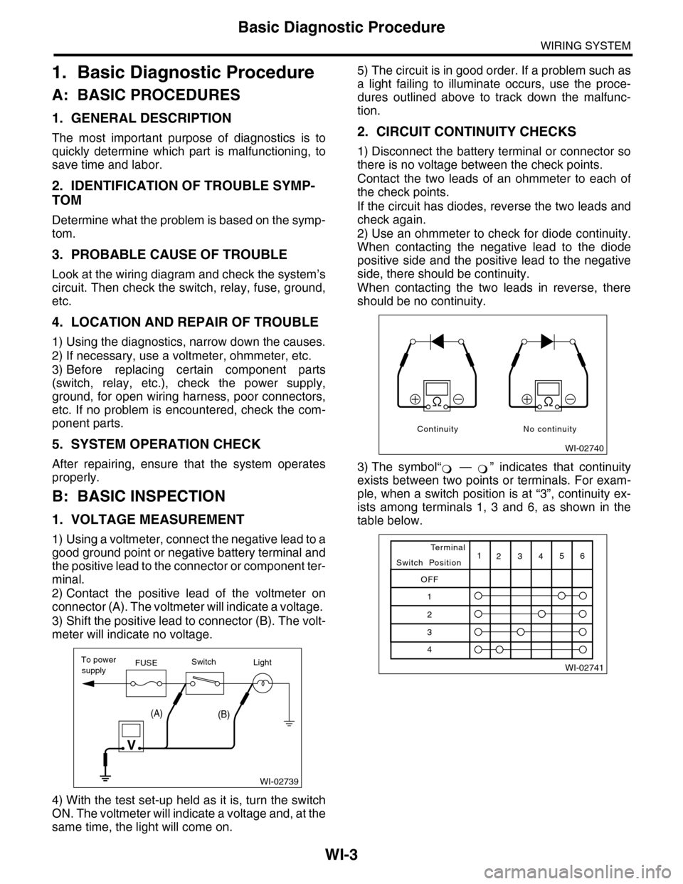
1) Using a voltmeter, connect the negative lead to a
good ground point or negative battery terminal and
the positive lead to the connector or component ter-
minal.
2) Contact the positive lead of the voltmeter on
connector (A). The voltmeter will indicate a voltage.
3) Shift the positive lead to connector (B). The volt-
meter will indicate no voltage.
4) With the test set-up held as it is, turn the switch
ON. The voltmeter will indicate a voltage and, at the
same time, the light will come on.
5) The circuit is in good order. If a problem such as
a light failing to illuminate occurs, use the proce-
dures outlined above to track down the malfunc-
tion.
2. CIRCUIT CONTINUITY CHECKS
1) Disconnect the battery terminal or connector so
there is no voltage between the check points.
Contact the two leads of an ohmmeter to each of
the check points.
If the circuit has diodes, reverse the two leads and
check again.
2) Use an ohmmeter to check for diode continuity.
When contacting the negative lead to the diode
positive side and the positive lead to the negative
side, there should be continuity.
When contacting the two leads in reverse, there
should be no continuity.
3) The symbol“ — ” indicates that continuity
exists between two points or terminals. For exam-
ple, when a switch position is at “3”, continuity ex-
ists among terminals 1, 3 and 6, as shown in the
table below.
WI-02739
To powerFUSEsupplySwitchLight
V
(A)(B)
WI-02740
Continuity No continuity
�
Page 2294 of 2453

WI-10
Basic Diagnostic Procedure
WIRING SYSTEM
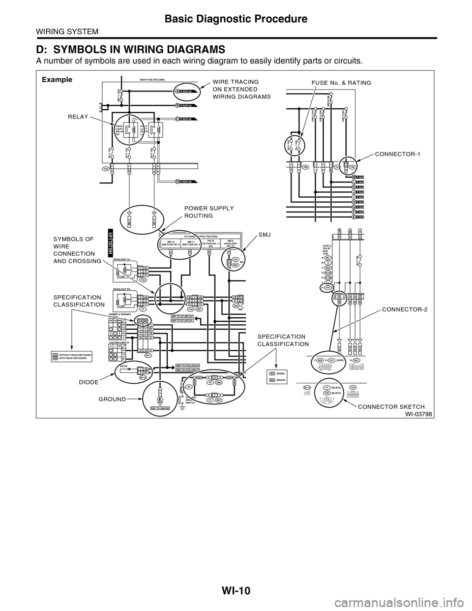
D: SYMBOLS IN WIRING DIAGRAMS
A number of symbols are used in each wiring diagram to easily identify parts or circuits.
WI-03798
LRLWRL3725
MAIN FUSE BOX (M/B)
MB-11MB-10
F39
P-SUP-02B
P-SUP-02A
P-SUP-02C
No.3 10ANo.9 15ANo.8 15A
SBF-1 100A
HEAD-LIGHTRELAYRH
HEAD-LIGHTRELAYLH
G
P-SUP-04D
H/L(2L)-01RLLWGRLB
TO POWER SUPPLY ROUTINGMB-10M/B FUSE NO. 8MB-11M/B FUSE NO. 9FB-16F/B FUSE NO. 11(IG)MB-5HEADLIGHTRELAY
LW 4R3YLLWRYL2
YB1RY2
LW2R1YL3
P
LW B 1RA1
F44
F45
F23
F7B61
B62
B
RL2R1YL3
B71
B112
LY8RY7YBB1716
3
1716
UPLOWPA S SHFHUHLE
SMJLB H1
B36SMJ
DIODE
: WITHOUT REAR DEFOGGER: WITH REAR DEFOGGER
PA R K I N GBRAKESWITCH
R4
OFFHCTCEL
LOWHIGH
HEADLIGHT RH
HEADLIGHT LH
LIGHTING SWITCH
DIMMER & PASSINGSWITCH
LOWHIGH
B51A:B52C:F41G: (GRAY)
(BLACK)(BLACK)
FB-37
D4D7BGD11
A2WR G4BLG1BR D10
FB-35FB-34
123456712345678
LgBOr
FUSE &RELAYBOX(F/B)
i5B:B51A:
B152D:B52C:
B158E:
F41G:F40F:
FB-36
A3BGG7
No.5 10A
P-SUP-03H
P-SUP-03F
P-SUP-04KP-SUP-04J
No.1 20ANo.2 15A
SBF-6 30A
LR2R3L1R3BW 2W
SBF-2 50ASBF-3 50ASBF-4 50A
F36F38F68
P-SUP-04E
P-SUP-04MP-SUP-04L
P-SUP-03I
P-SUP-04G
12345678
F44B11212F23
123
F7
SPECIFICATIONCLASSIFICATION
SPECIFICATIONCLASSIFICATION
2
LY1313
WROR
ORWRREF. TO FOG (H4)-01
REF. TO ST (MT)-01REF. TO ST (AT)-01
REF. TO FOG (H6)-01
REF. TO GND-02
CONNECTOR-1
FUSE No. & RATING
CONNECTOR-2
CONNECTOR SKETCH
RELAY
WIRE TRACINGON EXTENDEDWIRING DIAGRAMS
Example
DIODE
GROUND
POWER SUPPLYROUTING
SMJSYMBOLS OFWIRECONNECTIONAND CROSSING
PP17R3B99
PP7R1B97
WGWGSDSD: WAGON: SEDANSDWG
Page 2295 of 2453

WI-11
Basic Diagnostic Procedure
WIRING SYSTEM
1. RELAY
A symbol used to indicate a relay.
2. CONNECTOR 1
The sketch of the connector indicates the one-pole
types.
3. WIRING CONNECTION
Some wiring diagrams are indicated in foldouts for
convenience. Wiring destinations are indicated
where necessary by corresponding symbols.
(When two pages are needed for clear indication)
4. FUSE NO. & RATING
The “FUSE No. & RATING“ corresponds with that
used in the fuse box (main fuse box, fuse and joint
box).
5. CONNECTOR 2
•Each connector is indicated by a symbol.
•Each terminal number is indicated in the corre-
sponding wiring diagram in an abbreviated form.
•For example, terminal number "G4" refers to No.
4 terminal of connector (G: F41) shown in the con-
nector sketch.
6. CONNECTOR SKETCH
•Each connector sketch clearly identifies the
shape and color of a connector as well as terminal
locations. Non-colored connectors are indicated in
white or natural color.
•When more than two types of connector number
are indicated in a connector sketch, it means that
the same type connectors are used.
7. GROUND
Each grounding point can be located easily by re-
ferring to the corresponding wiring harness.
8. DIODE
A symbol is used to indicate a diode.
9. WIRE TRACING ON EXTENDED WIRING
DIAGRAMS
For a wiring diagram extending over at least two
pages, a symbol (consisting of the same characters
with arrows), facilitates wire tracing from one page
to the next.
A ←→ B, B ←→ B
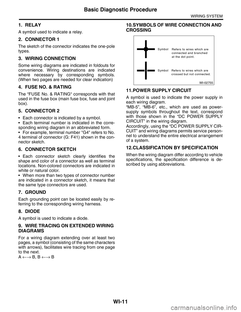
10.SYMBOLS OF WIRE CONNECTION AND
CROSSING
11.POWER SUPPLY CIRCUIT
A symbol is used to indicate the power supply in
each wiring diagram.
“MB-5”, “MB-6”, etc., which are used as power-
supply symbols throughout the text, correspond
with those shown in the “DC POWER SUPPLY
CIRCUIT” in the wiring diagram.
Accordingly, using the “DC POWER SUPPLY CIR-
CUIT” and wiring diagrams permits service person-
nel to understand the entire electrical arrangement
of a system.
12.CLASSIFICATION BY SPECIFICATION
When the wiring diagram differ according to vehicle
specifications, the specification difference is de-
scribed by using abbreviations.
WI-02755
Symbol
Symbol Refers to wires which arecrossed but not connected.
Refers to wires which areconnected and branchedat the dot point.