Page 652 of 2453

SL-23
Keyless Entry System
SECURITY AND LOCKS
12.CHECK IGNITION SWITCH ILLUMINATION.
13.CHECK HORN OPERATION
Step Check Yes No
1CHECK FUSE.
Remove and visually check the fuse No. 14 (in
the main fuse box).
Is the fuse blown out? Replace the fuse
with a new one.
Go to step 2.
2CHECK POWER SUPPLY.
1) Disconnect the ignition switch illumination
harness connector.
2) Measure the voltage between harness con-
nector terminal and chassis ground.
Connector & terminal
(B414) No. 2 (+) — Chassis ground (– ):
Is the voltage more than 10 V? Go to step 3.Check the harness
for open circuits
and shorts
between the igni-
tion switch illumi-
nation and fuse.
3CHECK IGNITION SWITCH ILLUMINATION
CIRCUIT.
1) Disconnect the harness connector of body
integrated unit and ignition switch illumination
harness connector.
2) Measure the resistance between body inte-
grated unit harness connector terminal and
ignition switch illumination harness connector
terminal.
Connector & terminal
(B280) No. 4 — (B414) No. 1:
Is the resistance less than 10
Ω?
Replace the igni-
tion switch illumi-
nation bulb with a
new one.
LI-35, REMOVAL,
Ignition Switch Illu-
mination.>
Check the harness
for open circuits
and shorts
between the body
integrated unit and
ignition switch illu-
mination.
Step Check Yes No
1CHECK HORN OPERATION.
Make sure the horn sounds when the horn
switch is pushed.
Does the horn sound? Go to step 2.Check the horn cir-
cuit.
2CHECK HORN OPERATION.
1) Disconnect the harness connector of body
integrated unit.
2) Connect the harness connector terminal to
ground using a suitable lead wire.
Connector & terminal
(B280) No. 11 (+) — Chassis ground (– ):
Does the horn sound? Check the body
integrated unit.
LAN(diag)-2, Basic
Diagnostic Proce-
dure.>
Check the harness
for open circuits
and/or shorts
between the body
integrated unit and
horn relay.
Page 1081 of 2453

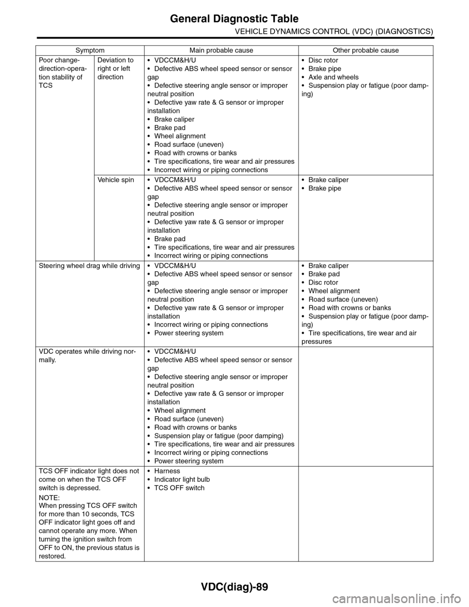
VDC(diag)-89
General Diagnostic Table
VEHICLE DYNAMICS CONTROL (VDC) (DIAGNOSTICS)
Po or ch a ng e -
direction-opera-
tion stability of
TCS
Deviation to
right or left
direction
•VDCCM&H/U
•Defective ABS wheel speed sensor or sensor
gap
•Defective steering angle sensor or improper
neutral position
•Defective yaw rate & G sensor or improper
installation
•Brake caliper
•Brake pad
•Wheel alignment
•Road surface (uneven)
•Road with crowns or banks
•Tire specifications, tire wear and air pressures
•Incorrect wiring or piping connections
•Disc rotor
•Brake pipe
•Axle and wheels
•Suspension play or fatigue (poor damp-
ing)
Ve h i c l e s p i n • V D C C M & H / U
•Defective ABS wheel speed sensor or sensor
gap
•Defective steering angle sensor or improper
neutral position
•Defective yaw rate & G sensor or improper
installation
•Brake pad
•Tire specifications, tire wear and air pressures
•Incorrect wiring or piping connections
•Brake caliper
•Brake pipe
Steering wheel drag while driving • VDCCM&H/U
•Defective ABS wheel speed sensor or sensor
gap
•Defective steering angle sensor or improper
neutral position
•Defective yaw rate & G sensor or improper
installation
•Incorrect wiring or piping connections
•Power steering system
•Brake caliper
•Brake pad
•Disc rotor
•Wheel alignment
•Road surface (uneven)
•Road with crowns or banks
•Suspension play or fatigue (poor damp-
ing)
•Tire specifications, tire wear and air
pressures
VDC operates while driving nor-
mally.
•VDCCM&H/U
•Defective ABS wheel speed sensor or sensor
gap
•Defective steering angle sensor or improper
neutral position
•Defective yaw rate & G sensor or improper
installation
•Wheel alignment
•Road surface (uneven)
•Road with crowns or banks
•Suspension play or fatigue (poor damping)
•Tire specifications, tire wear and air pressures
•Incorrect wiring or piping connections
•Power steering system
TCS OFF indicator light does not
come on when the TCS OFF
switch is depressed.
NOTE:When pressing TCS OFF switch
for more than 10 seconds, TCS
OFF indicator light goes off and
cannot operate any more. When
turning the ignition switch from
OFF to ON, the previous status is
restored.
•Harness
•Indicator light bulb
•TCS OFF switch
Symptom Main probable cause Other probable cause
Page 2255 of 2453

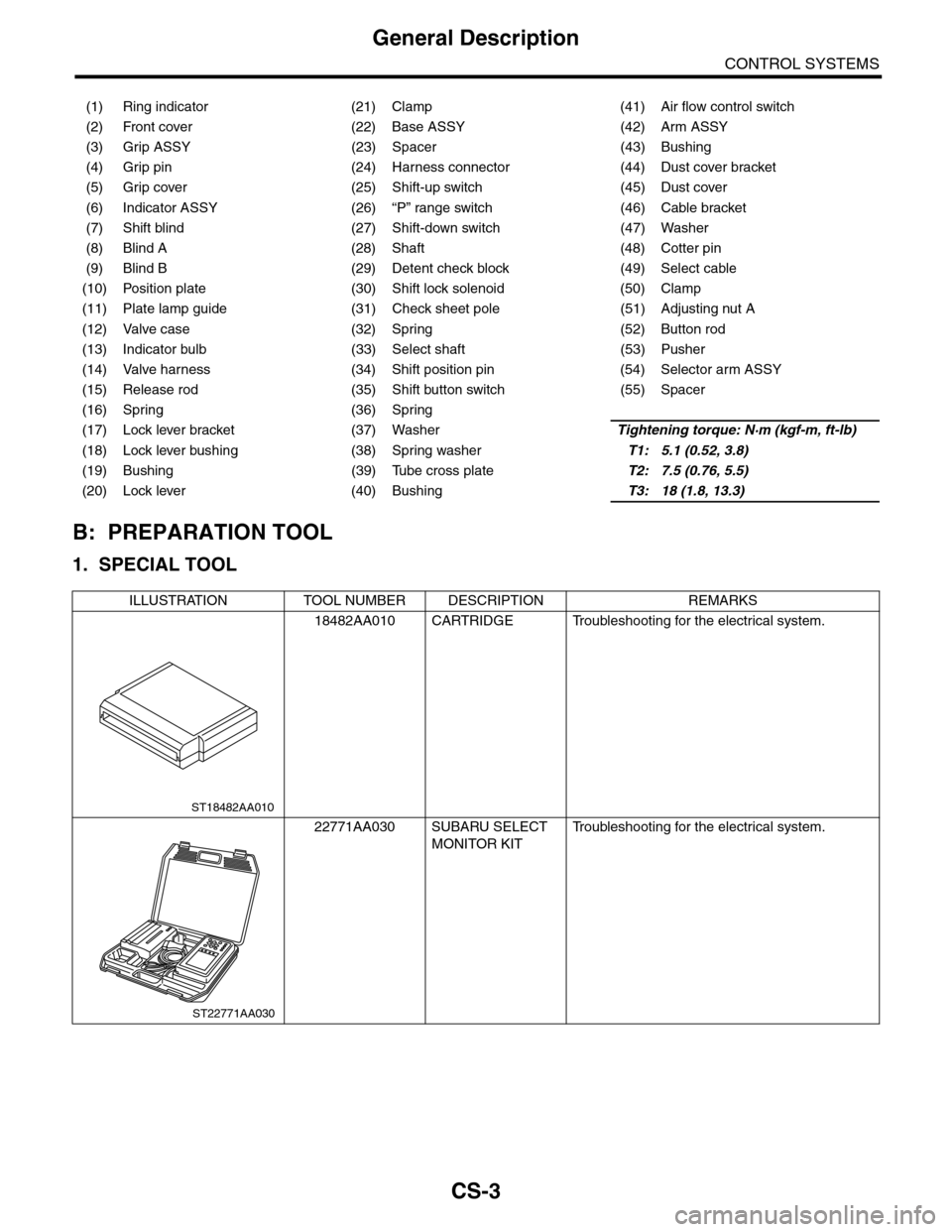
CS-3
General Description
CONTROL SYSTEMS
B: PREPARATION TOOL
1. SPECIAL TOOL
(1) Ring indicator (21) Clamp (41) Air flow control switch
(2) Front cover (22) Base ASSY (42) Arm ASSY
(3) Grip ASSY (23) Spacer (43) Bushing
(4) Grip pin (24) Harness connector (44) Dust cover bracket
(5) Grip cover (25) Shift-up switch (45) Dust cover
(6) Indicator ASSY (26) “P” range switch (46) Cable bracket
(7) Shift blind (27) Shift-down switch (47) Washer
(8) Blind A (28) Shaft (48) Cotter pin
(9) Blind B (29) Detent check block (49) Select cable
(10) Position plate (30) Shift lock solenoid (50) Clamp
(11) Plate lamp guide (31) Check sheet pole (51) Adjusting nut A
(12) Valve case (32) Spring (52) Button rod
(13) Indicator bulb (33) Select shaft (53) Pusher
(14) Valve harness (34) Shift position pin (54) Selector arm ASSY
(15) Release rod (35) Shift button switch (55) Spacer
(16) Spring (36) Spring
(17) Lock lever bracket (37) WasherTightening torque: N·m (kgf-m, ft-lb)
(18) Lock lever bushing (38) Spring washerT1: 5.1 (0.52, 3.8)
(19) Bushing (39) Tube cross plateT2: 7.5 (0.76, 5.5)
(20) Lock lever (40) BushingT3: 18 (1.8, 13.3)
ILLUSTRATION TOOL NUMBER DESCRIPTION REMARKS
18482AA010 CARTRIDGE Troubleshooting for the electrical system.
22771AA030 SUBARU SELECT
MONITOR KIT
Tr o u b l e s h o o t i n g f o r t h e e l e c t r i c a l s y s t e m .
ST18482AA010
ST22771AA030
Page 2273 of 2453
CS-21
Select Lever
CONTROL SYSTEMS
6) Remove the indicator lamp and then remove the
bulb.
7) Remove the shift lock solenoid assembly.
8) Remove the indicator assembly.
9) Remove the bulb case.
10) Remove the plate lamp guide.
11) Remove the position plate.
12) Remove the blind assembly.
CS-00612
CS-00613
CS-00614
CS-00615
CS-00616
ST-00617
CS-00618