Page 535 of 2453

LI-2
General Description
LIGHTING SYSTEM
1. General Description
A: SPECIFICATION
B: CAUTION
•Before removing or installing parts, always disconnect the battery ground cable from battery. When replac-
ing the audio, control module and other parts provided with memory functions, record the memory contents
before disconnecting the battery ground cable. Otherwise, the memory is cleared.
•Reassemble the parts in the reverse order of disassembly procedure unless otherwise indicated.
•Adjust parts to the given specifications.
•Connect the connectors securely during reassembly.
•After reassembly, make sure functional parts operate smoothly.
WARNING:
•The air bag system wiring harness is routed near electrical parts and switches. Airbag system
wiring harnesses and connectors are yellow. Do not use electrical test equipment on these cir-
cuits.
•Be careful not to damage the air bag system wiring harness when servicing electrical parts and
switches.
C: PREPARATION TOOL
1. GENERAL TOOL
HeadlightHalogen type low beam 12 V — 55 W
Halogen type high beam 12 V — 65 W
Fr o nt t ur n si gn a l, p ar k in g 1 2 V — 27 / 8 W
Fr o nt si d e m ar ke r li gh t12 V — 5 W
Fr o nt fog li g ht12 V — 55 W
Side turn signal light 12 V — 2.7 W (LED)
Rear combination lightStop/Tail light/Rear side marker light 12 V — 21/5 W
Tu r n s i g n a l l i g h t 1 2 V — 2 1 W
Rear finisher light12 V — 3.8 W
Back-up light12 V — 16 W
License plate light12 V — 5 W
High-mounted stop light 12 V — 1.3 W (LED)
Room light12 V — 8 W
Spot map light12 V — 8 W
Luggage room light12 V — 13 W
Rear gate light12 V — 5 W
Glove box light12 V — 1.4 W
Door step light12 V — 3.5 W
TOOL NAME REMARKS
Circuit tester Used for measuring resistance and voltage.
Page 635 of 2453

SL-6
General Description
SECURITY AND LOCKS
5. KEYLESS ENTRY SYSTEM
B: CAUTION
•Before disassembling or reassembling parts, al-
ways disconnect the battery ground cable from bat-
tery. When repairing the audio, control module, etc.
which are provided with memory functions, record
the memory contents before disconnecting the
ground cable from battery. Otherwise, these con-
tents are erased upon disconnection.
•Reassemble the parts in the reverse order of dis-
assembly unless otherwise indicated.
•Adjust the parts to the specifications described in
this manual if so designated.
•Connect the connectors securely during reas-
sembly.
•After reassembly, ensure the functional parts op-
erate smoothly.
•The air bag system wiring harness is routed near
electrical parts and switches.
•Airbag system wiring harnesses and connectors
are yellow. Do not use the electrical test equipment
on these circuits.
•Be careful not to damage the airbag system wir-
ing harness when servicing the ignition key cylin-
der.
(1) Keyless entry control module (3) Door switch (5) Horn
(2) Rear gate latch switch (4) Body integrated unit (6) Keyless buzzer
SL-00440
(2)
(3)
(4)
(5)
(5)
(6)
(1)
Page 687 of 2453
SR-3
General Description
SUNROOF/T-TOP/CONVERTIBLE TOP (SUNROOF)
B: CAUTION
•Before disassembling or reassembling parts, al-
ways disconnect the battery ground cable from bat-
tery. When replacing the audio, control unit, and
other parts provided with memory functions, record
the memory contents before disconnecting the bat-
tery ground cable in order to prevent memory dele-
tion.
•Reassemble the parts in the reverse order of dis-
assembly unless otherwise indicated.
•Adjust parts to the given specifications.
•Connect the connectors securely for reassem-
bly.
•After reassembly, make sure functional parts op-
erate smoothly.
C: PREPARATION TOOL
1. GENERAL TOOL
TOOL NAME REMARKS
Circuit Tester Used for measuring resistance and
voltage.
TO RX®T20Used for the removal of the sun roof
lid and sunshade.
Page 1164 of 2453
EN(H6DO)(diag)-3
Check List for Interview
ENGINE (DIAGNOSTICS)
2. Check List for Interview
A: CHECK
1. CHECK LIST No. 1
Check the following item when problem has occurred.
NOTE:
Use copies of this page for interviewing customers.
Customer’s name Engine No.
Date of sale Fuel brand
Date of repair Odometer readingkm
V. I . N . miles
Weather Fine
Cloudy
Rainy
Snowy
Various/Others:
Ambient air temperature °C (°F)
Hot
Warm
Cool
Cold
Place Highway
Suburbs
Inner city
Uphill
Downhill
Rough road
Others:
Engine temperature Cold
Warming-up
After warming-up
Any temperature
Others:
Engine speed rpm
Ve h i c l e s p e e d k m / h ( M P H )
Driving conditions Not affected
At starting
While idling
At racing
While accelerating
While cruising
While decelerating
While turning (RH/LH)
Headlight ON/ OFFRear defogger ON/ OFF
Blower ON/ OFFAudio ON/ OFF
A/C compressor ON/ OFFCar phone ON/ OFF
Radiator fan ON/ OFF
Fr o nt wi pe r ON/ OFF
Rear wiper ON/ OFF
Page 2304 of 2453

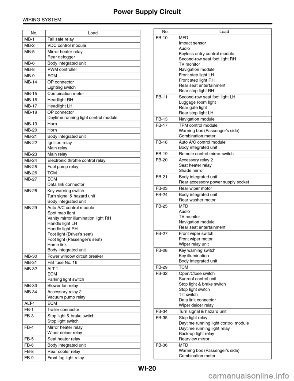
WI-20
Power Supply Circuit
WIRING SYSTEM
No. Load
MB-1 Fail safe relay
MB-2 VDC control module
MB-5 Mirror heater relay
Rear defogger
MB-6 Body integrated unit
MB-8 PWM controller
MB-9 ECM
MB-14 OP connector
Lighting switch
MB-15 Combination meter
MB-16 Headlight RH
MB-17 Headlight LH
MB-18 OP connector
Daytime running light control module
MB-19 Horn
MB-20 Horn
MB-21 Body integrated unit
MB-22 Ignition relay
Main relay
MB-23 Main relay
MB-24 Electronic throttle control relay
MB-25 Fuel pump relay
MB-26 TCM
MB-27 ECM
Data link connector
MB-28 Key warning switch
Tu r n s i g n a l & h a z a r d u n i t
Body integrated unit
MB-29 Auto A/C control module
Spot map light
Va n i t y m i r r o r i l l u m i n a t i o n l i g h t R H
Handle light LH
Handle light RH
Foot light (Driver’s seat)
Foot light (Passenger’s seat)
Home link
Body integrated unit
MB-30 Power window circuit breaker
MB-31 F/B fuse No. 16
MB-32 ALT-1
ECM
Par king light switch
MB-33 Blower fan relay
MB-34 Accessory relay 2
Va c u u m p u m p r e l ay
ALT-1 ECM
FB-1 Trailer connector
FB-3 Stop light & brake switch
Stop light switch
FB-4 Mirror heater relay
Wiper deicer relay
FB-5 Seat heater relay
FB-6 Body integrated unit
FB-8 Rear cooler relay
FB-9 Front fog light relay
FB-10 MFD
Impact sensor
Audio
Keyless entr y control module
Second-row seat foot light RH
TV monitor
Navigation module
Fr o n t s te p li gh t LH
Fr o n t s te p li gh t RH
Rear seat entertainment
Rear step light RH
FB-11 Second-row seat foot light LH
Luggage room light
Rear gate light
Rear step light LH
FB-13 Navigation module
FB-17 TPM control module
War ning box (Passenger’s side)
Combination meter
FB-18 Auto A/C control module
Body integrated unit
FB-19 Remote control mirror switch
FB-20 Accessory relay 2
Seat heater relay
Shade mirror
FB-21 Body integrated unit
Rear accessory power supply socket
FB-23 Rear wiper motor
FB-24 Body integrated unit
Rear washer motor
FB-25 MFD
Audio
TV monitor
Navigation module
Rear seat entertainment
FB-27 Front wiper switch
Fr o n t wi p er mo t or
Wiper relay unit
FB-28 Key warning switch
Key illumination
Body integrated unit
FB-29 TCM
FB-32 Open/Close switch
Sunroof control unit
Stop light & brake switch
Stop light switch
Tilt switch
Data link connector
Wiper deicer relay
FB-34 Turn signal & hazard unit
FB-35 Stop light relay
Daytime running light control module
Daytime running light relay
Back-up light relay
Rearview mirror
FB-36 MFD
War ning box (Passenger’s side)
Combination meter
No. Load
Page 2308 of 2453

WI-24
Ground Circuit
WIRING SYSTEM
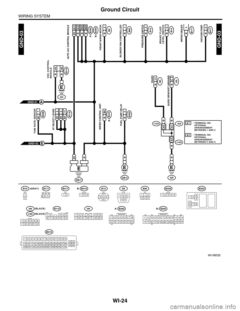
WI-08032
GND-03GND-03
B177B2
WIPER DEICER
B10B3
PRESSURE SWITCH
B8B2
FRONT WIPER MOTOR
BRAKE FLUIDLEVEL SWITCH
A:
B16B2B282
B:
B410
B:
B283B A16
AUTO A/C CONTROL MODULE
B86B1
BLOWER FAN CONTROLLER
B116BY 2BY 6BY 11
AT SELECT LEVER
B B2
WIPER CONTROL UNIT
3
B362B
FUEL PUMP RELAY
RADIOi85B 11i29B
AUDIO BRACKET GROUND
GND-02E
BB
GB-7
BBY
GRGB-5
(GRAY)B16
12
B10
2314
B8
13245
B362
12
78
3456
GND-01A
B177
B417B2
VACUUM PUMP
2
B359BY
1
YAW RATE SENSOR
BY A11B A16B B24B B26
B310
VDC CONTROLMODULEB 43B 46
GV
21
B283A:
345678910
16 17 18 19 20
121112132425262122231415
B282B:
B:
12345678
910 1112 1314 1516
B310
1234
1516171819202122232425262728293031323334353637383940414245464344568910 11 12 13 147
B417
1212345123
B359B410B86
i100
i100i99BB
B
1*
2*
2*
123456789101112
i99(BLACK)
i100(BLACK)
: TERMINAL NO. OPTIONAL ARRANGEMENT BETWEEN 1 AND 2
: TERMINAL NO. OPTIONAL ARRANGEMENT BETWEEN 5 AND 6
1*
2*
i85
2345817910111213614
B116
123467891011512
12345
Page 2393 of 2453

WI-109
Audio System
WIRING SYSTEM
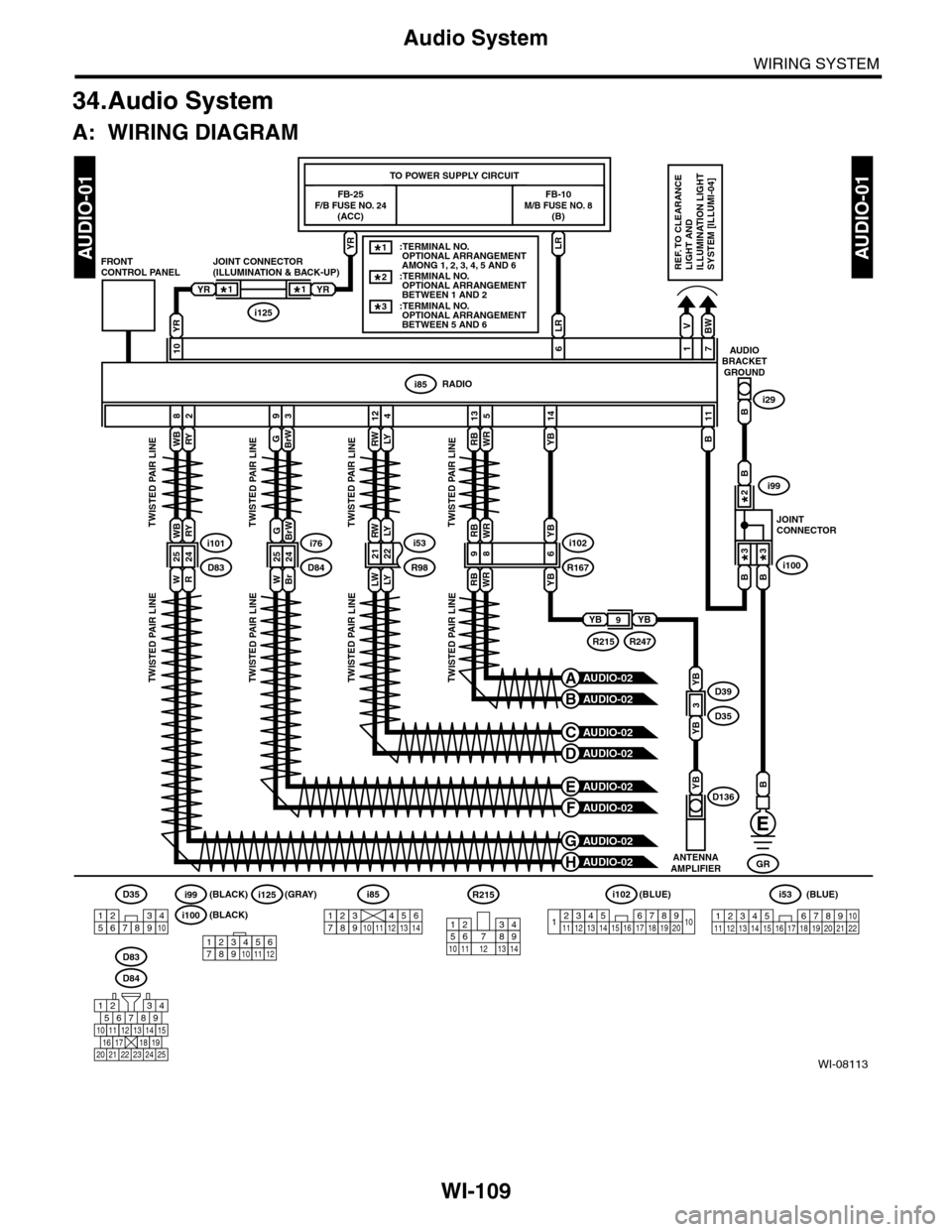
34.Audio System
A: WIRING DIAGRAM
WI-08113
AUDIO-01AUDIO-01
ANTENNAAMPLIFIER
YBD136
LRYR
FB-25F/B FUSE NO. 24(ACC)
FB-10M/B FUSE NO. 8(B)
TO POWER SUPPLY CIRCUIT
RWLY
RWLY
124
RADIOi85
V
1
BW
7
BrW
3
G
9
B
11
YB
14
YR
10AUDIOBRACKETGROUND
Bi29
i53
LWLYR982122
JOINT CONNECTOR(ILLUMINATION & BACK-UP)FRONTCONTROL PANEL
YRYR
i125
LR
6
B
GR
i85
1234567891011121314
D84
567821943
10
2422 23 25
11121314151617181920 21
WBRY
WBRY
82
i101
WR
2524D83
TWISTED PAIR LINETWISTED PAIR LINETWISTED PAIR LINETWISTED PAIR LINE
TWISTED PAIR LINETWISTED PAIR LINETWISTED PAIR LINETWISTED PAIR LINE
RBWR
RBWR
135
i102
RBWR
R16798
YB
YB
6i76
D84WBr
GBrW
2524
REF. TO CLEARANCELIGHT ANDILLUMINATION LIGHTSYSTEM [ILLUMI-04]
D83
1*1*
B
B
B
AUDIO-02H
AUDIO-02G
AUDIO-02F
AUDIO-02E
AUDIO-02D
AUDIO-02C
AUDIO-02B
AUDIO-02A
JOINTCONNECTOR
i100
i99
3*3*
2*
YBYB9
R247R215
D39
D35YB
YB
3
1234567891413121110151617181920
i102(BLUE)
123 8910411 12 13 14 15 16567171819202122
i53(BLUE)D35
12345678910
R215
12
10 115634897131412123456789101112
i125(GRAY)
i100(BLACK)
i99(BLACK)
::TERMINAL NO. OPTIONAL ARRANGEMENT BETWEEN 1 AND 2 ::TERMINAL NO. OPTIONAL ARRANGEMENT BETWEEN 5 AND 6
2*
3*
::TERMINAL NO. OPTIONAL ARRANGEMENT AMONG 1, 2, 3, 4, 5 AND 6
1*
Page 2394 of 2453

WI-110
Audio System
WIRING SYSTEM
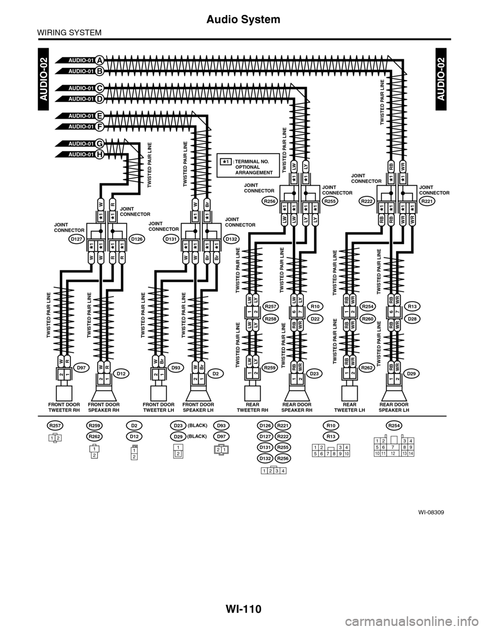
WI-08309
AUDIO-02AUDIO-02
FRONT DOORTWEETER RHFRONT DOORTWEETER LH
R
12D97W
W
WW
R
RR
TWISTED PAIR LINE
FRONT DOORSPEAKER RH
W
12D12R
AUDIO-01A
AUDIO-01B
AUDIO-01C
AUDIO-01D
AUDIO-01E
AUDIO-01F
AUDIO-01G
AUDIO-01H
JOINTCONNECTOR
D127
JOINTCONNECTOR
D126
Br
12D93W
W
WW
Br
BrBr
FRONT DOORSPEAKER LH
W
12D2Br
JOINTCONNECTOR
D131
JOINTCONNECTOR
D132
LW
LWLW
LY
LYLY
JOINTCONNECTOR
R256
JOINTCONNECTOR
R255
REARTWEETER RH
LY
21R259LW
REAR DOORSPEAKER RH
RB
21D23WR
TWISTED PAIR LINETWISTED PAIR LINE
TWISTED PAIR LINETWISTED PAIR LINE
TWISTED PAIR LINE
TWISTED PAIR LINETWISTED PAIR LINE
TWISTED PAIR LINETWISTED PAIR LINETWISTED PAIR LINETWISTED PAIR LINE
TWISTED PAIR LINETWISTED PAIR LINETWISTED PAIR LINETWISTED PAIR LINE
R10
RB
LW
WR
LY
D2267R257
LW
LW
LY
LY
R25812
RB
RBRB
WR
WRWR
JOINTCONNECTOR
R222
JOINTCONNECTOR
R221
REARTWEETER LH
WR
21R262RB
REAR DOORSPEAKER LH
RB
21D29WR
R13
RB
RB
WR
WR
D2867R254
RB
RB
WR
WR
R26012
*1 : TERMINAL NO. OPTIONAL ARRANGEMENT
*1*1*1*1*1*1*1*1
*1*1*1*1*1*1*1*1
*1*1*1*1
*1*1*1*1
R257
12D97
D93
21
D23
D29
12
R262
R259
121
R254
12
10115634897131412
R13
R10
D132
D131
R256
R255
D127
D126
R222
R221
15234678910
1234
D12
D2
12
(BLACK)
(BLACK)