2009 SUBARU TRIBECA monitor
[x] Cancel search: monitorPage 1272 of 2453
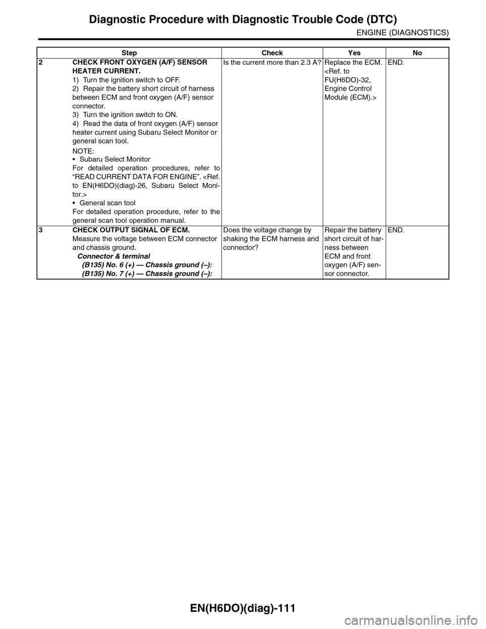
EN(H6DO)(diag)-111
Diagnostic Procedure with Diagnostic Trouble Code (DTC)
ENGINE (DIAGNOSTICS)
2CHECK FRONT OXYGEN (A/F) SENSOR
HEATER CURRENT.
1) Turn the ignition switch to OFF.
2) Repair the battery short circuit of harness
between ECM and front oxygen (A/F) sensor
connector.
3) Turn the ignition switch to ON.
4) Read the data of front oxygen (A/F) sensor
heater current using Subaru Select Monitor or
general scan tool.
NOTE:•Subaru Select Monitor
For detailed operation procedures, refer to
“READ CURRENT DATA FOR ENGINE”.
tor.>
•General scan tool
For detailed operation procedure, refer to the
general scan tool operation manual.
Is the current more than 2.3 A? Replace the ECM.
Engine Control
Module (ECM).>
END.
3CHECK OUTPUT SIGNAL OF ECM.
Measure the voltage between ECM connector
and chassis ground.
Connector & terminal
(B135) No. 6 (+) — Chassis ground (–):
(B135) No. 7 (+) — Chassis ground (–):
Does the voltage change by
shaking the ECM harness and
connector?
Repair the battery
short circuit of har-
ness between
ECM and front
oxygen (A/F) sen-
sor connector.
END.
Step Check Yes No
Page 1275 of 2453
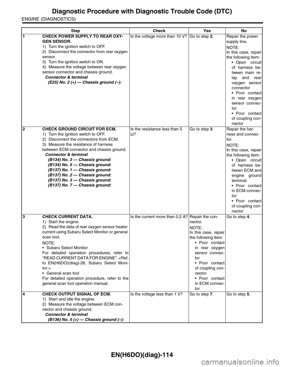
EN(H6DO)(diag)-114
Diagnostic Procedure with Diagnostic Trouble Code (DTC)
ENGINE (DIAGNOSTICS)
Step Check Yes No
1CHECK POWER SUPPLY TO REAR OXY-
GEN SENSOR.
1) Turn the ignition switch to OFF.
2) Disconnect the connector from rear oxygen
sensor.
3) Turn the ignition switch to ON.
4) Measure the voltage between rear oxygen
sensor connector and chassis ground.
Connector & terminal
(E25) No. 2 (+) — Chassis ground (–):
Is the voltage more than 10 V? Go to step 2.Repair the power
supply line.
NOTE:
In this case, repair
the following item:
•Open circuit
of harness be-
tween main re-
lay and rear
oxygen sensor
connector
•Poor contact
in rear oxygen
sensor connec-
tor
•Poor contact
of coupling con-
nector
2CHECK GROUND CIRCUIT FOR ECM.
1) Turn the ignition switch to OFF.
2) Disconnect the connectors from ECM.
3) Measure the resistance of harness
between ECM connector and chassis ground.
Connector & terminal
(B134) No. 3 — Chassis ground:
(B134) No. 5 — Chassis ground:
(B137) No. 1 — Chassis ground:
(B137) No. 2 — Chassis ground:
(B137) No. 3 — Chassis ground:
(B137) No. 7 — Chassis ground:
Is the resistance less than 5
Ω?
Go to step 3.Repair the har-
ness and connec-
tor.
NOTE:In this case, repair
the following item:
•Open circuit
of harness be-
tween ECM and
engine ground
terminal
•Poor contact
in ECM connec-
tor
•Poor contact
of coupling con-
nector
3CHECK CURRENT DATA.
1) Start the engine.
2) Read the data of rear oxygen sensor heater
current using Subaru Select Monitor or general
scan tool.
NOTE:•Subaru Select Monitor
For detailed operation procedures, refer to
“READ CURRENT DATA FOR ENGINE”.
tor.>
•General scan tool
For detailed operation procedure, refer to the
general scan tool operation manual.
Is the current more than 0.2 A? Repair the con-
nector.
NOTE:In this case, repair
the following item:
•Poor contact
in rear oxygen
sensor connec-
tor
•Poor contact
of coupling con-
nector
•Poor contact
in ECM connec-
tor
Go to step 4.
4CHECK OUTPUT SIGNAL OF ECM.
1) Start and idle the engine.
2) Measure the voltage between ECM con-
nector and chassis ground.
Connector & terminal
(B136) No. 5 (+) — Chassis ground (–):
Is the voltage less than 1 V? Go to step 7.Go to step 5.
Page 1276 of 2453
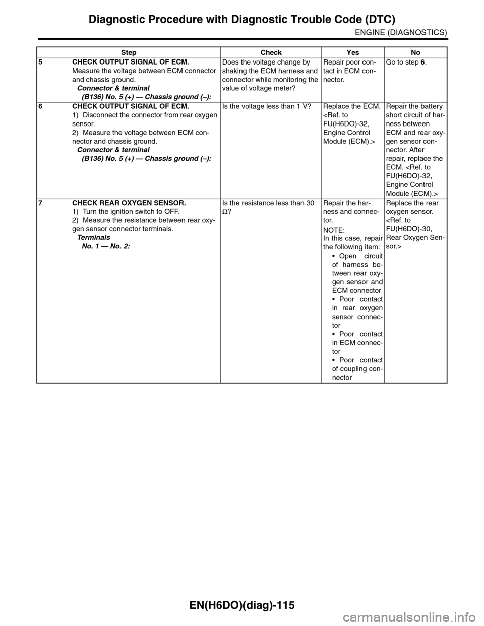
EN(H6DO)(diag)-115
Diagnostic Procedure with Diagnostic Trouble Code (DTC)
ENGINE (DIAGNOSTICS)
5CHECK OUTPUT SIGNAL OF ECM.
Measure the voltage between ECM connector
and chassis ground.
Connector & terminal
(B136) No. 5 (+) — Chassis ground (–):
Does the voltage change by
shaking the ECM harness and
connector while monitoring the
value of voltage meter?
Repair poor con-
tact in ECM con-
nector.
Go to step 6.
6CHECK OUTPUT SIGNAL OF ECM.
1) Disconnect the connector from rear oxygen
sensor.
2) Measure the voltage between ECM con-
nector and chassis ground.
Connector & terminal
(B136) No. 5 (+) — Chassis ground (–):
Is the voltage less than 1 V? Replace the ECM.
Engine Control
Module (ECM).>
Repair the battery
short circuit of har-
ness between
ECM and rear oxy-
gen sensor con-
nector. After
repair, replace the
ECM.
Engine Control
Module (ECM).>
7CHECK REAR OXYGEN SENSOR.
1) Turn the ignition switch to OFF.
2) Measure the resistance between rear oxy-
gen sensor connector terminals.
Te r m i n a l s
No. 1 — No. 2:
Is the resistance less than 30
Ω?
Repair the har-
ness and connec-
tor.
NOTE:
In this case, repair
the following item:
•Open circuit
of harness be-
tween rear oxy-
gen sensor and
ECM connector
•Poor contact
in rear oxygen
sensor connec-
tor
•Poor contact
in ECM connec-
tor
•Poor contact
of coupling con-
nector
Replace the rear
oxygen sensor.
Rear Oxygen Sen-
sor.>
Step Check Yes No
Page 1279 of 2453
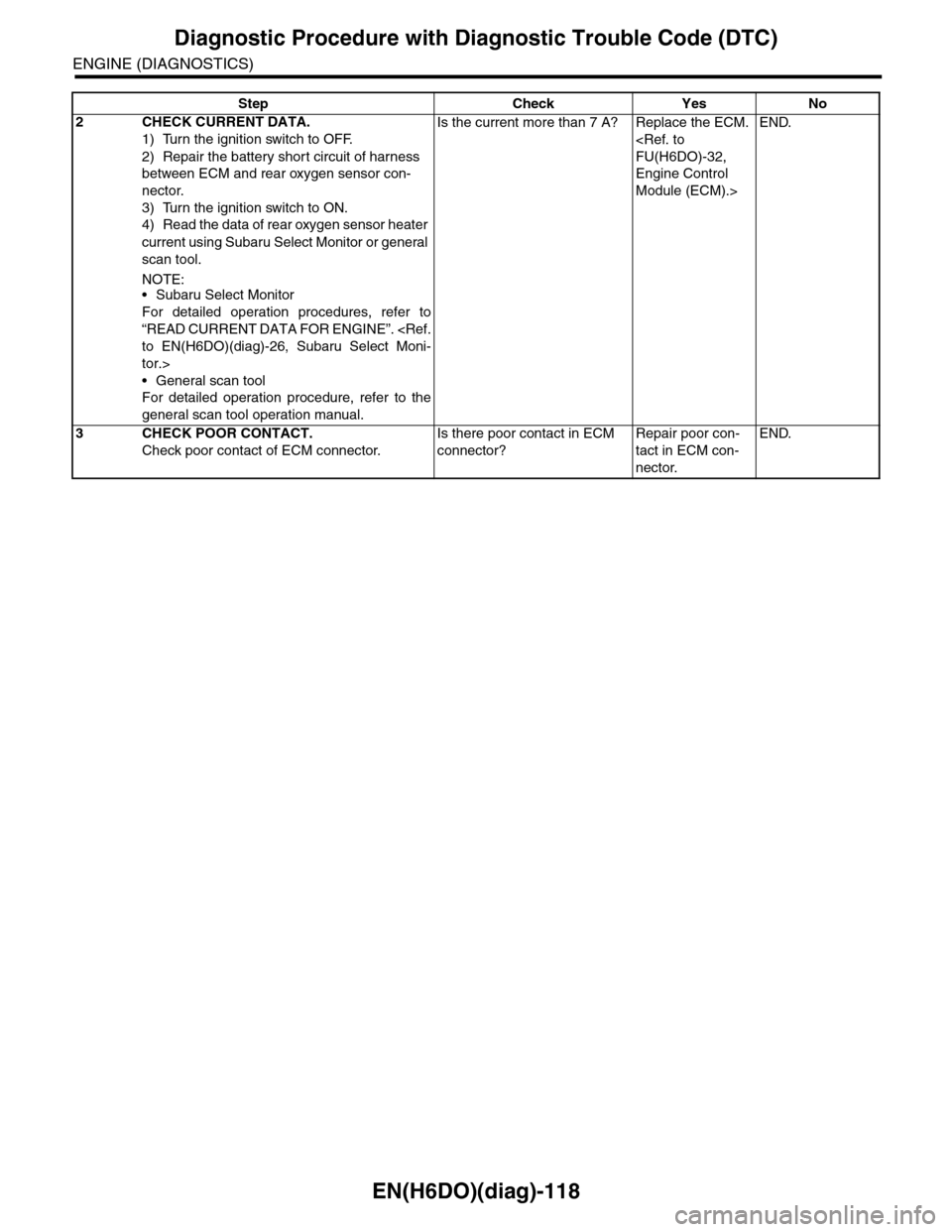
EN(H6DO)(diag)-118
Diagnostic Procedure with Diagnostic Trouble Code (DTC)
ENGINE (DIAGNOSTICS)
2CHECK CURRENT DATA.
1) Turn the ignition switch to OFF.
2) Repair the battery short circuit of harness
between ECM and rear oxygen sensor con-
nector.
3) Turn the ignition switch to ON.
4) Read the data of rear oxygen sensor heater
current using Subaru Select Monitor or general
scan tool.
NOTE:•Subaru Select Monitor
For detailed operation procedures, refer to
“READ CURRENT DATA FOR ENGINE”.
tor.>
•General scan tool
For detailed operation procedure, refer to the
general scan tool operation manual.
Is the current more than 7 A? Replace the ECM.
Engine Control
Module (ECM).>
END.
3CHECK POOR CONTACT.
Check poor contact of ECM connector.
Is there poor contact in ECM
connector?
Repair poor con-
tact in ECM con-
nector.
END.
Step Check Yes No
Page 1281 of 2453
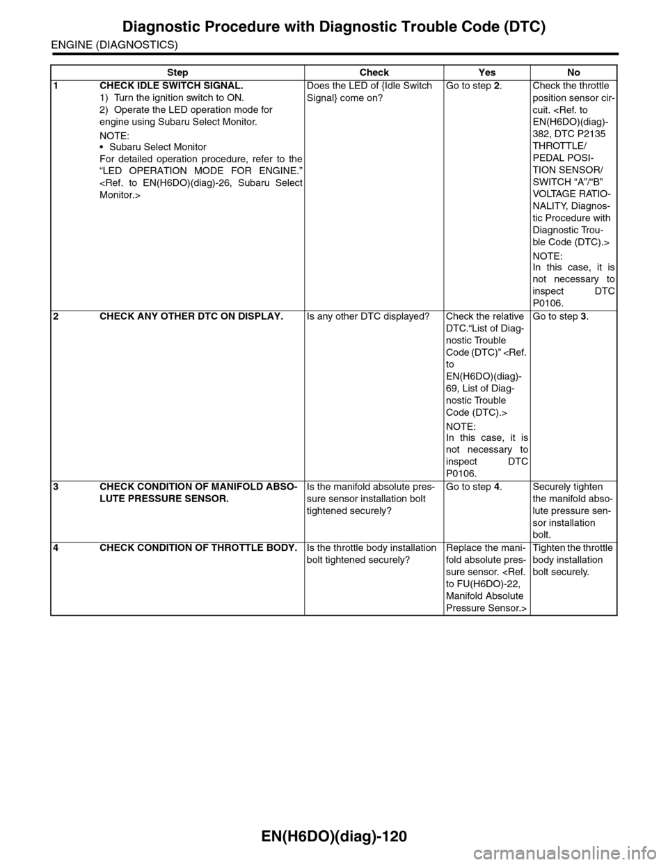
EN(H6DO)(diag)-120
Diagnostic Procedure with Diagnostic Trouble Code (DTC)
ENGINE (DIAGNOSTICS)
Step Check Yes No
1CHECK IDLE SWITCH SIGNAL.
1) Turn the ignition switch to ON.
2) Operate the LED operation mode for
engine using Subaru Select Monitor.
NOTE:•Subaru Select Monitor
For detailed operation procedure, refer to the
“LED OPERATION MODE FOR ENGINE.”
Does the LED of {Idle Switch
Signal} come on?
Go to step 2.Check the throttle
position sensor cir-
cuit.
382, DTC P2135
THROTTLE/
PEDAL POSI-
TION SENSOR/
SWITCH “A”/“B”
VOLTAGE RATIO-
NALITY, Diagnos-
tic Procedure with
Diagnostic Trou-
ble Code (DTC).>
NOTE:
In this case, it is
not necessary to
inspect DTC
P0106.
2CHECK ANY OTHER DTC ON DISPLAY.Is any other DTC displayed? Check the relative
DTC.“List of Diag-
nostic Trouble
Code (DTC)”
EN(H6DO)(diag)-
69, List of Diag-
nostic Trouble
Code (DTC).>
NOTE:
In this case, it is
not necessary to
inspect DTC
P0106.
Go to step 3.
3CHECK CONDITION OF MANIFOLD ABSO-
LUTE PRESSURE SENSOR.
Is the manifold absolute pres-
sure sensor installation bolt
tightened securely?
Go to step 4.Securely tighten
the manifold abso-
lute pressure sen-
sor installation
bolt.
4CHECK CONDITION OF THROTTLE BODY.Is the throttle body installation
bolt tightened securely?
Replace the mani-
fold absolute pres-
sure sensor.
Manifold Absolute
Pressure Sensor.>
Tighten the throttle
body installation
bolt securely.
Page 1293 of 2453
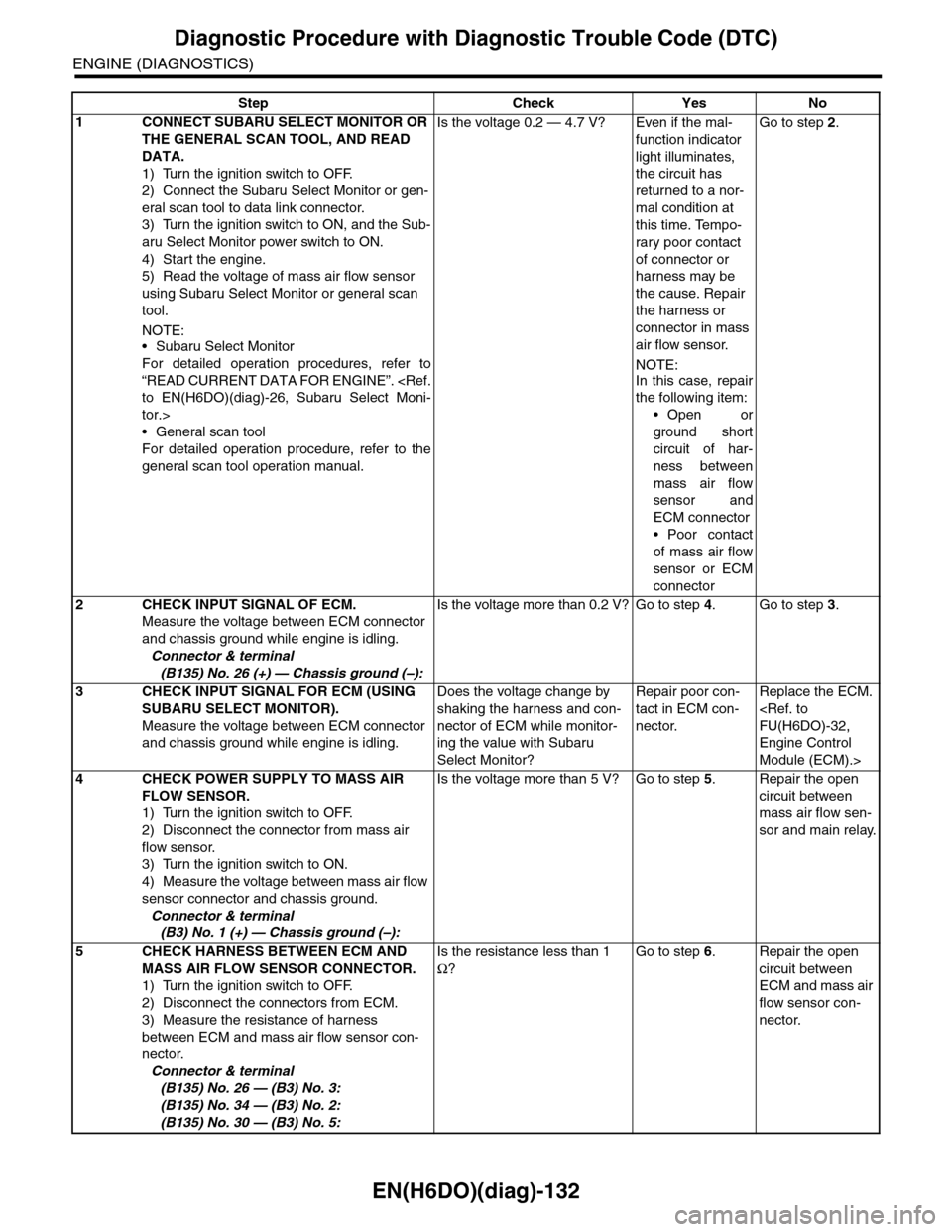
EN(H6DO)(diag)-132
Diagnostic Procedure with Diagnostic Trouble Code (DTC)
ENGINE (DIAGNOSTICS)
Step Check Yes No
1CONNECT SUBARU SELECT MONITOR OR
THE GENERAL SCAN TOOL, AND READ
DATA.
1) Turn the ignition switch to OFF.
2) Connect the Subaru Select Monitor or gen-
eral scan tool to data link connector.
3) Turn the ignition switch to ON, and the Sub-
aru Select Monitor power switch to ON.
4) Start the engine.
5) Read the voltage of mass air flow sensor
using Subaru Select Monitor or general scan
tool.
NOTE:•Subaru Select Monitor
For detailed operation procedures, refer to
“READ CURRENT DATA FOR ENGINE”.
tor.>
•General scan tool
For detailed operation procedure, refer to the
general scan tool operation manual.
Is the voltage 0.2 — 4.7 V? Even if the mal-
function indicator
light illuminates,
the circuit has
returned to a nor-
mal condition at
this time. Tempo-
rary poor contact
of connector or
harness may be
the cause. Repair
the harness or
connector in mass
air flow sensor.
NOTE:
In this case, repair
the following item:
•Open or
ground short
circuit of har-
ness between
mass air flow
sensor and
ECM connector
•Poor contact
of mass air flow
sensor or ECM
connector
Go to step 2.
2CHECK INPUT SIGNAL OF ECM.
Measure the voltage between ECM connector
and chassis ground while engine is idling.
Connector & terminal
(B135) No. 26 (+) — Chassis ground (–):
Is the voltage more than 0.2 V? Go to step 4.Go to step 3.
3CHECK INPUT SIGNAL FOR ECM (USING
SUBARU SELECT MONITOR).
Measure the voltage between ECM connector
and chassis ground while engine is idling.
Does the voltage change by
shaking the harness and con-
nector of ECM while monitor-
ing the value with Subaru
Select Monitor?
Repair poor con-
tact in ECM con-
nector.
Replace the ECM.
Engine Control
Module (ECM).>
4CHECK POWER SUPPLY TO MASS AIR
FLOW SENSOR.
1) Turn the ignition switch to OFF.
2) Disconnect the connector from mass air
flow sensor.
3) Turn the ignition switch to ON.
4) Measure the voltage between mass air flow
sensor connector and chassis ground.
Connector & terminal
(B3) No. 1 (+) — Chassis ground (–):
Is the voltage more than 5 V? Go to step 5.Repair the open
circuit between
mass air flow sen-
sor and main relay.
5CHECK HARNESS BETWEEN ECM AND
MASS AIR FLOW SENSOR CONNECTOR.
1) Turn the ignition switch to OFF.
2) Disconnect the connectors from ECM.
3) Measure the resistance of harness
between ECM and mass air flow sensor con-
nector.
Connector & terminal
(B135) No. 26 — (B3) No. 3:
(B135) No. 34 — (B3) No. 2:
(B135) No. 30 — (B3) No. 5:
Is the resistance less than 1
Ω?
Go to step 6.Repair the open
circuit between
ECM and mass air
flow sensor con-
nector.
Page 1296 of 2453
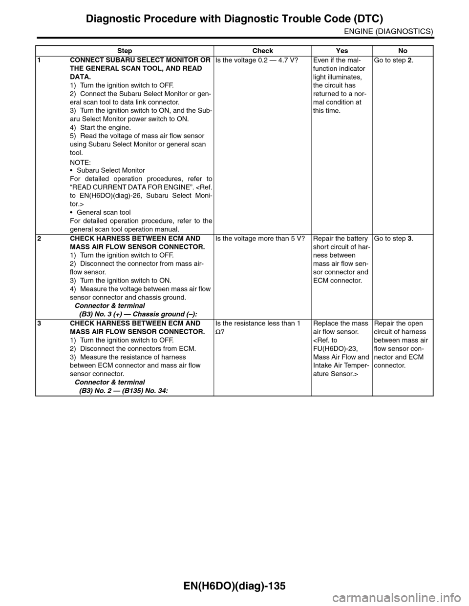
EN(H6DO)(diag)-135
Diagnostic Procedure with Diagnostic Trouble Code (DTC)
ENGINE (DIAGNOSTICS)
Step Check Yes No
1CONNECT SUBARU SELECT MONITOR OR
THE GENERAL SCAN TOOL, AND READ
DATA.
1) Turn the ignition switch to OFF.
2) Connect the Subaru Select Monitor or gen-
eral scan tool to data link connector.
3) Turn the ignition switch to ON, and the Sub-
aru Select Monitor power switch to ON.
4) Start the engine.
5) Read the voltage of mass air flow sensor
using Subaru Select Monitor or general scan
tool.
NOTE:•Subaru Select Monitor
For detailed operation procedures, refer to
“READ CURRENT DATA FOR ENGINE”.
tor.>
•General scan tool
For detailed operation procedure, refer to the
general scan tool operation manual.
Is the voltage 0.2 — 4.7 V? Even if the mal-
function indicator
light illuminates,
the circuit has
returned to a nor-
mal condition at
this time.
Go to step 2.
2CHECK HARNESS BETWEEN ECM AND
MASS AIR FLOW SENSOR CONNECTOR.
1) Turn the ignition switch to OFF.
2) Disconnect the connector from mass air-
flow sensor.
3) Turn the ignition switch to ON.
4) Measure the voltage between mass air flow
sensor connector and chassis ground.
Connector & terminal
(B3) No. 3 (+) — Chassis ground (–):
Is the voltage more than 5 V? Repair the battery
short circuit of har-
ness between
mass air flow sen-
sor connector and
ECM connector.
Go to step 3.
3CHECK HARNESS BETWEEN ECM AND
MASS AIR FLOW SENSOR CONNECTOR.
1) Turn the ignition switch to OFF.
2) Disconnect the connectors from ECM.
3) Measure the resistance of harness
between ECM connector and mass air flow
sensor connector.
Connector & terminal
(B3) No. 2 — (B135) No. 34:
Is the resistance less than 1
Ω?
Replace the mass
air flow sensor.
Mass Air Flow and
Intake Air Temper-
ature Sensor.>
Repair the open
circuit of harness
between mass air
flow sensor con-
nector and ECM
connector.
Page 1298 of 2453
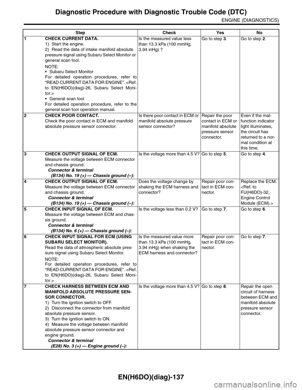
EN(H6DO)(diag)-137
Diagnostic Procedure with Diagnostic Trouble Code (DTC)
ENGINE (DIAGNOSTICS)
Step Check Yes No
1CHECK CURRENT DATA.
1) Start the engine.
2) Read the data of intake manifold absolute
pressure signal using Subaru Select Monitor or
general scan tool.
NOTE:
•Subaru Select Monitor
For detailed operation procedures, refer to
“READ CURRENT DATA FOR ENGINE”.
tor.>
•General scan tool
For detailed operation procedure, refer to the
general scan tool operation manual.
Is the measured value less
than 13.3 kPa (100 mmHg,
3.94 inHg) ?
Go to step 3.Go to step 2.
2CHECK POOR CONTACT.
Check the poor contact in ECM and manifold
absolute pressure sensor connector.
Is there poor contact in ECM or
manifold absolute pressure
sensor connector?
Repair the poor
contact in ECM or
manifold absolute
pressure sensor
connector.
Even if the mal-
function indicator
light illuminates,
the circuit has
returned to a nor-
mal condition at
this time.
3CHECK OUTPUT SIGNAL OF ECM.
Measure the voltage between ECM connector
and chassis ground.
Connector & terminal
(B134) No. 19 (+) — Chassis ground (–):
Is the voltage more than 4.5 V? Go to step 5.Go to step 4.
4CHECK OUTPUT SIGNAL OF ECM.
Measure the voltage between ECM connector
and chassis ground.
Connector & terminal
(B134) No. 19 (+) — Chassis ground (–):
Does the voltage change by
shaking the ECM harness and
connector?
Repair poor con-
tact in ECM con-
nector.
Replace the ECM.
Engine Control
Module (ECM).>
5CHECK INPUT SIGNAL OF ECM.
Measure the voltage between ECM and chas-
sis ground.
Connector & terminal
(B134) No. 6 (+) — Chassis ground (–):
Is the voltage less than 0.2 V? Go to step 7.Go to step 6.
6CHECK INPUT SIGNAL FOR ECM (USING
SUBARU SELECT MONITOR).
Read the data of atmospheric absolute pres-
sure signal using Subaru Select Monitor.
NOTE:For detailed operation procedures, refer to
“READ CURRENT DATA FOR ENGINE”.
tor.>
Is the measured value more
than 13.3 kPa (100 mmHg,
3.94 inHg) when shaking the
ECM harness and connector?
Repair poor con-
tact in ECM con-
nector.
Go to step 7.
7CHECK HARNESS BETWEEN ECM AND
MANIFOLD ABSOLUTE PRESSURE SEN-
SOR CONNECTOR.
1) Turn the ignition switch to OFF.
2) Disconnect the connector from manifold
absolute pressure sensor.
3) Turn the ignition switch to ON.
4) Measure the voltage between manifold
absolute pressure sensor connector and
engine ground.
Connector & terminal
(E28) No. 3 (+) — Engine ground (–):
Is the voltage more than 4.5 V? Go to step 8.Repair the open
circuit of harness
between ECM and
manifold absolute
pressure sensor
connector.