Page 1017 of 2453
VDC(diag)-25
Warning Light Illumination Pattern
VEHICLE DYNAMICS CONTROL (VDC) (DIAGNOSTICS)
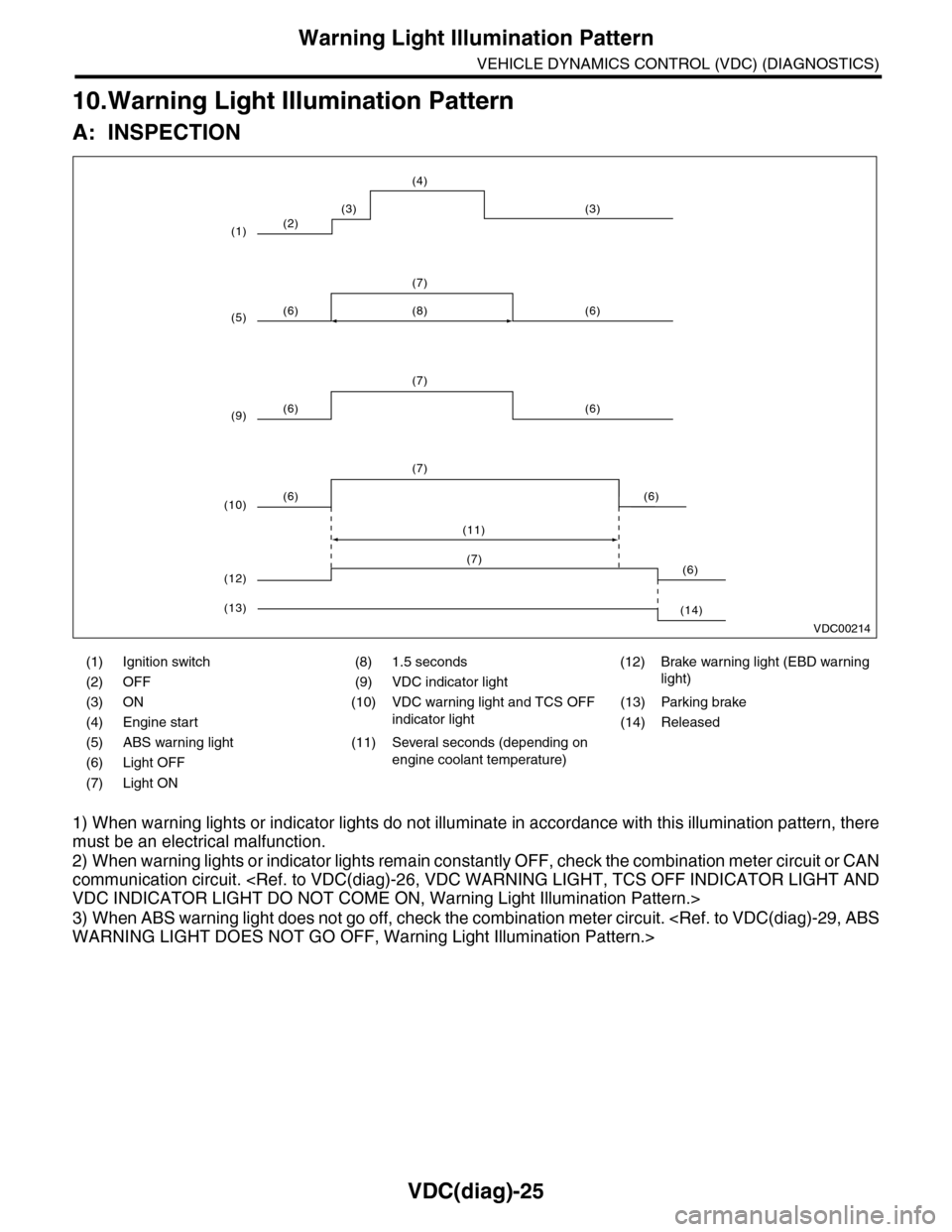
10.Warning Light Illumination Pattern
A: INSPECTION
1) When warning lights or indicator lights do not illuminate in accordance with this illumination pattern, there
must be an electrical malfunction.
2) When warning lights or indicator lights remain constantly OFF, check the combination meter circuit or CAN
communication circuit.
VDC INDICATOR LIGHT DO NOT COME ON, Warning Light Illumination Pattern.>
3) When ABS warning light does not go off, check the combination meter circuit.
WARNING LIGHT DOES NOT GO OFF, Warning Light Illumination Pattern.>
(1) Ignition switch (8) 1.5 seconds (12) Brake warning light (EBD warning
light)(2) OFF (9) VDC indicator light
(3) ON (10) VDC warning light and TCS OFF
indicator light
(13) Parking brake
(4) Engine start (14) Released
(5) ABS warning light (11) Several seconds (depending on
engine coolant temperature)(6) Light OFF
(7) Light ON
VDC00214
(2)
(6) (6)
(7)
(6) (6)
(7)
(8)
(6) (6)
(7)
(11)
(3) (3)
(4)
(1)
(5)
(9)
(10)
(6)(7)
(12)
(14)(13)
Page 1020 of 2453
VDC(diag)-28
Warning Light Illumination Pattern
VEHICLE DYNAMICS CONTROL (VDC) (DIAGNOSTICS)
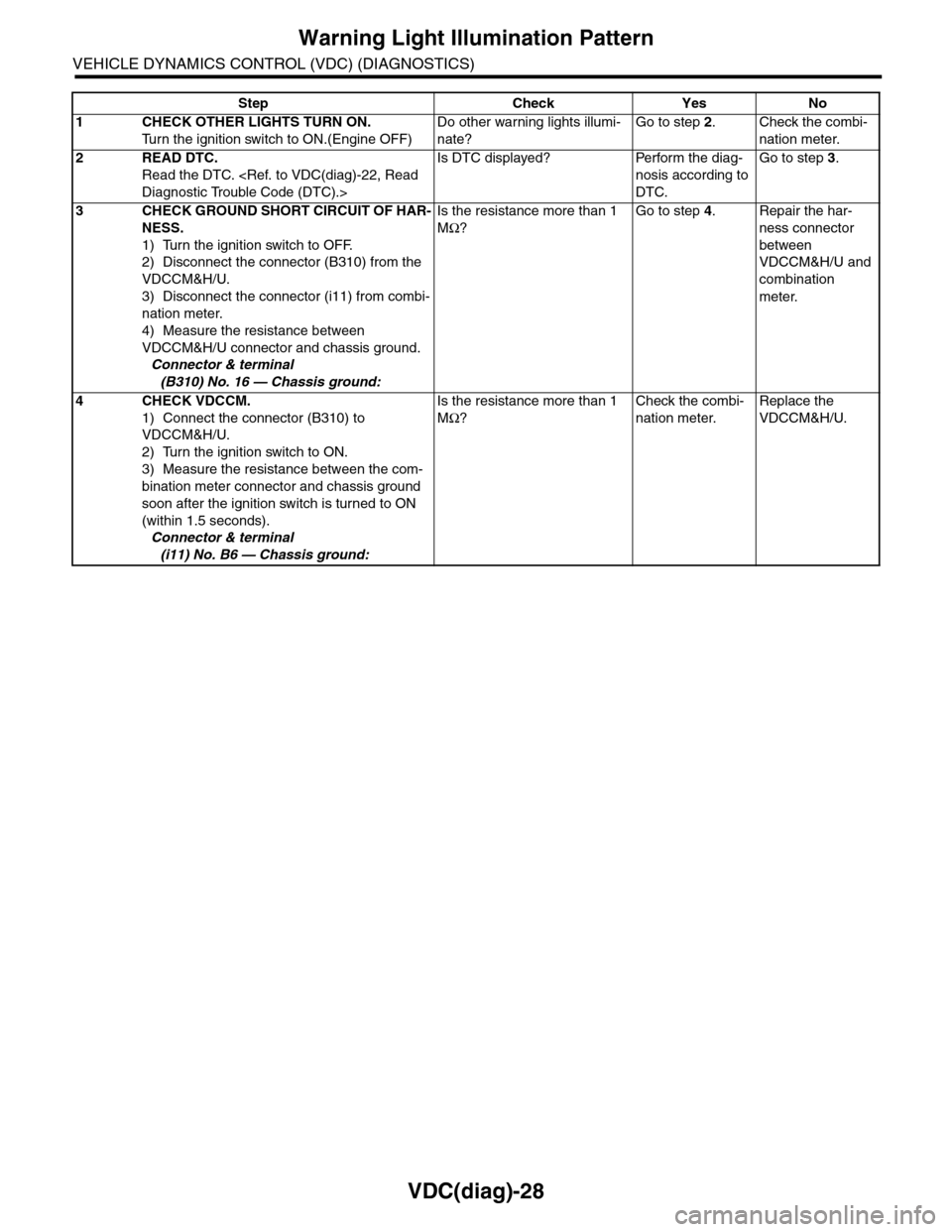
Step Check Yes No
1CHECK OTHER LIGHTS TURN ON.
Tu r n t h e i g n i t i o n s w i t c h t o O N . ( E n g i n e O F F )
Do other warning lights illumi-
nate?
Go to step 2.Check the combi-
nation meter.
2READ DTC.
Read the DTC.
Diagnostic Trouble Code (DTC).>
Is DTC displayed? Perform the diag-
nosis according to
DTC.
Go to step 3.
3CHECK GROUND SHORT CIRCUIT OF HAR-
NESS.
1) Turn the ignition switch to OFF.
2) Disconnect the connector (B310) from the
VDCCM&H/U.
3) Disconnect the connector (i11) from combi-
nation meter.
4) Measure the resistance between
VDCCM&H/U connector and chassis ground.
Connector & terminal
(B310) No. 16 — Chassis ground:
Is the resistance more than 1
MΩ?
Go to step 4.Repair the har-
ness connector
between
VDCCM&H/U and
combination
meter.
4CHECK VDCCM.
1) Connect the connector (B310) to
VDCCM&H/U.
2) Turn the ignition switch to ON.
3) Measure the resistance between the com-
bination meter connector and chassis ground
soon after the ignition switch is turned to ON
(within 1.5 seconds).
Connector & terminal
(i11) No. B6 — Chassis ground:
Is the resistance more than 1
MΩ?
Check the combi-
nation meter.
Replace the
VDCCM&H/U.
Page 1023 of 2453
VDC(diag)-31
Warning Light Illumination Pattern
VEHICLE DYNAMICS CONTROL (VDC) (DIAGNOSTICS)
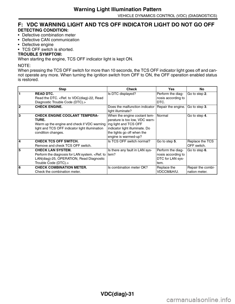
F: VDC WARNING LIGHT AND TCS OFF INDICATOR LIGHT DO NOT GO OFF
DETECTING CONDITION:
•Defective combination meter
•Defective CAN communication
•Defective engine
•TCS OFF switch is shorted.
TROUBLE SYMPTOM:
When starting the engine, TCS OFF indicator light is kept ON.
NOTE:
When pressing the TCS OFF switch for more than 10 seconds, the TCS OFF indicator light goes off and can-
not operate any more. When turning the ignition switch from OFF to ON, the OFF operation enabled status
is restored.
Step Check Yes No
1READ DTC.
Read the DTC.
Diagnostic Trouble Code (DTC).>
Is DTC displayed? Perform the diag-
nosis according to
DTC.
Go to step 2.
2CHECK ENGINE.Does the malfunction indicator
light illuminate?
Repair the engine. Go to step 3.
3CHECK ENGINE COOLANT TEMPERA-
TURE.
War m up the engine and check if VDC war ning
light and TCS OFF indicator light illumination
condition changes.
When the engine coolant tem-
perature is too low, VDC warn-
ing light and TCS OFF
indicator light illuminate. Do
the lights go off when the
engine is warmed-up?
Normal Go to step 4.
4CHECK TCS OFF SWITCH.
Remove and check TCS OFF switch.
Is TCS OFF switch normal? Go to step 5.Replace the TCS
OFF switch.
5CHECK LAN SYSTEM.
Perfor m the diagnosis for LAN system.
LAN(diag)-25, OPERATION, Read Diagnostic
Tr o u b l e C o d e ( D T C ) . >
Is there any fault in LAN sys-
tem?
Pe r for m t h e d ia g -
nosis according to
DTC for LAN sys-
tem.
Go to step 6.
6CHECK COMBINATION METER.
Check the combination meter.
Is combination meter OK? Replace the
VDCCM&H/U.
Repair the combi-
nation meter.
Page 1041 of 2453
VDC(diag)-49
Diagnostic Procedure with Diagnostic Trouble Code (DTC)
VEHICLE DYNAMICS CONTROL (VDC) (DIAGNOSTICS)
X: DTC C0042 POWER VOLTAGE MALFUNCTION
DTC DETECTING CONDITION:
CHECK THE VDCCM&H/U power supply voltage.
TROUBLE SYMPTOM:
•ABS does not operate.
•EBD may not operate.
•VDC does not operate.
NOTE:
Warning lights go off if voltage returns.
Page 1165 of 2453
EN(H6DO)(diag)-4
Check List for Interview
ENGINE (DIAGNOSTICS)
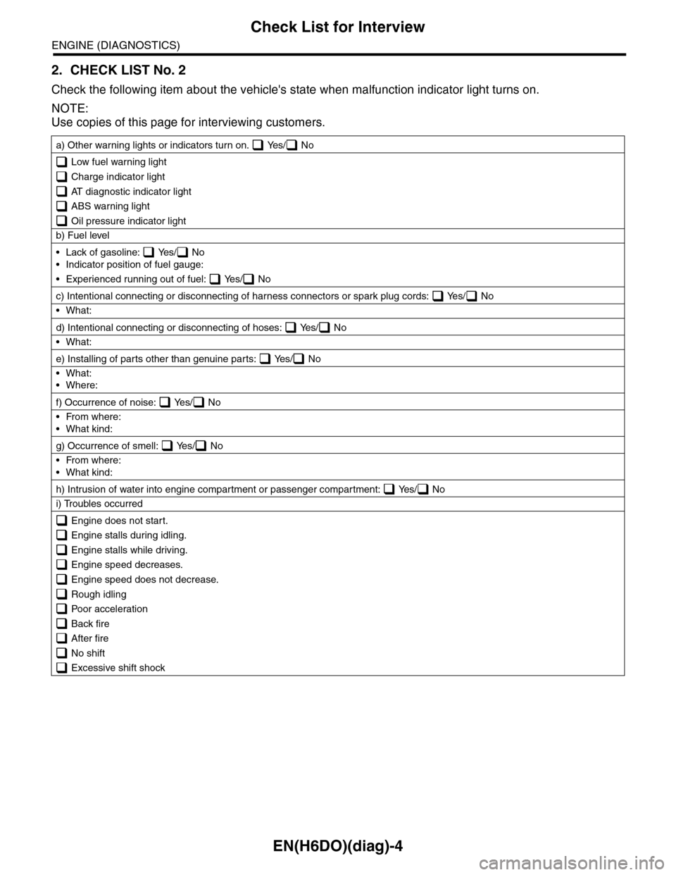
2. CHECK LIST No. 2
Check the following item about the vehicle's state when malfunction indicator light turns on.
NOTE:
Use copies of this page for interviewing customers.
a) Other warning lights or indicators turn on. Yes/ No
Low fuel warning light
Charge indicator light
AT diagnostic indicator light
ABS warning light
Oil pressure indicator light
b) Fuel level
•Lack of gasoline: Yes/ No
•Indicator position of fuel gauge:
•Experienced running out of fuel: Yes/ No
c) Intentional connecting or disconnecting of harness connectors or spark plug cords: Yes/ No
•What:
d) Intentional connecting or disconnecting of hoses: Yes/ No
•What:
e) Installing of parts other than genuine parts: Yes/ No
•What:
•Where:
f) Occurrence of noise: Yes/ No
•From where:
•What kind:
g) Occurrence of smell: Yes/ No
•From where:
•What kind:
h) Intrusion of water into engine compartment or passenger compartment: Yes/ No
i) Troubles occurred
Engine does not start.
Engine stalls during idling.
Engine stalls while driving.
Engine speed decreases.
Engine speed does not decrease.
Rough idling
Poor acceleration
Back fire
After fire
No shift
Excessive shift shock
Page 2336 of 2453
WI-52
AT Control System
WIRING SYSTEM
WI-08058
5AT-015AT-01FB-36F/B FUSE NO. 5(IG)
TO POWER SUPPLY CIRCUIT
BrW
BY
5AT-02A
5AT-02B
A3A4
PV
A29A30
BYBY
A15A16
REF. TO GROUND CIRCUIT [GND-05]
LCD(RANGE POSITION/GEAR POSITION)
MICRO COMPUTER
AT OIL TEMPERATUREWARNING LIGHT
CAN TRANSCEIVER & RECEIVER
DIMMER & STABILIZINGPOWER CIRCUIT
I/F
DRIVER
COMBINATIONMETER
i10A:AW DWA R N I N GLIGHTSPORTINDICATORLIGHT
TWISTED PAIR LINE
TWISTED PAIR LINE
BrW
JOINT CONNECTOR
i127
i1261*
2*
BrW
2*
: TERMINAL NO. OPTIONAL ARRANGEMENT AMONG 7, 8 AND 92*
: TERMINAL NO. OPTIONAL ARRANGEMENT AMONG 1, 2, 3, 4, 5 AND 63*
: TERMINAL NO. OPTIONAL ARRANGEMENT AMONG 7, 8, 9, 10, 11 AND 124*
: TERMINAL NO. OPTIONAL ARRANGEMENT AMONG 10, 11 AND 121*
PP
JOINT CONNECTOR
i128
3*3*
VV4*4*
i10
19 20 2115 16 17 182223242526272829301234568910 11 12 13 147
A:
123456789101112
i128
123456789101112
i126(BLACK) (BLUE) (GREEN)
i127(BLACK)
Page 2342 of 2453
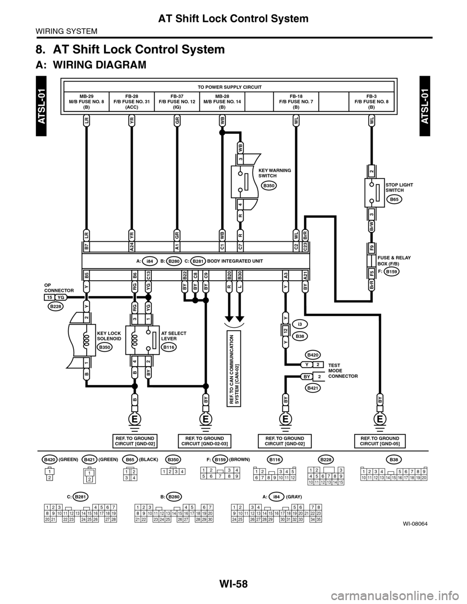
WI-58
AT Shift Lock Control System
WIRING SYSTEM
8. AT Shift Lock Control System
A: WIRING DIAGRAM
WI-08064
ATSL-01ATSL-01
B65(BLACK)(GREEN) (BROWN)
(GRAY)
F:B350
1234
B159
157628349
B228
131415
123456789101112
5467821931022 23111213141524 25 26 2716171828 29192021 30
B280B:
56782194310242223 25111213141526 27 281617181920 21
B281C:
YRLRGRWBWLWL
B350
BrRWL
BrW
C23C2
R
C7
WB
C1
GR
A1
LR
BYY
B7
YR
A24
B5A21
Y
A3
BY
C9
BY
C8
BY
B22B30B20
YG
C13
LRYG
B6
R
WB
BrR
F9
F5
FUSE & RELAYBOX (F/B)
TESTMODECONNECTOR
STOP LIGHTSWITCH
KEY WARNINGSWITCH
BODY INTEGRATED UNIT
OPCONNECTOR
KEY LOCKSOLENOID
B159
i3
B38
B421
B420
F:
i84A:
B228
B280B:B281C:
B65
3
4
31
BBY
24
YG15
RG
RG
Y
2
B
1
BYBYB
B350
AT SELECTLEVER
B116
A: i84
1234567891011121415161718192021222324252627282930313233343513
REF. TO GROUNDCIRCUIT [GND-05]
BY
REF. TO GROUNDCIRCUIT [GND-02]REF. TO GROUNDCIRCUIT [GND-02-03]REF. TO GROUNDCIRCUIT [GND-02]
FB-28F/B FUSE NO. 31(ACC)
MB-29M/B FUSE NO. 8(B)
FB-37F/B FUSE NO. 12(IG)
MB-28M/B FUSE NO. 14(B)
FB-18F/B FUSE NO. 7(B)
FB-3F/B FUSE NO. 8(B)
TO POWER SUPPLY CIRCUIT
2
3
1234
REF. TO CAN COMMUNICATIONSYSTEM [CAN-02]
12
Y
Y
2
2
Y
BY
12
B421(GREEN)B420
121
B116
123467891011512
B38
1234 5678910 11 12 13 14 15 16 17 18 19 20