Page 2043 of 2453
5AT-27
Automatic Transmission Fluid
AUTOMATIC TRANSMISSION
C: CONDITION CHECK
NOTE:
When replacing ATF, check the inside condition of transmission body by inspecting the drained ATF.
Fluid condition Trouble and possible cause Corrective action
Large amount of metallic pieces are
found.
Internal metal parts of transmission body are
excessively wor n.
Replace ATF and check if AT operates
correctly.
Is thick and is a varnish-form fluid. Clutch etc. is burned.Replace ATF and check the AT body or
vehicle for faulty.
Clouded fluid or bubbles are found in
fluid.Water is mixed.Replace ATF and check the water enter-
ing point.
Page 2047 of 2453
5AT-31
Time Lag Test
AUTOMATIC TRANSMISSION
6. Time Lag Test
A: INSPECTION
NOTE:
When the select lever is shifted while the engine is
idling, there will be a certain time elapse or lag be-
fore shock is felt. Using this, check the condition of
forward brake, reverse brake, 1st one-way clutch,
forward one-way clutch and 3rd one-way clutch.
•Perform the test at normal operation fluid tem-
perature of 70 — 80°C (158 — 176°F).
•Be sure to allow a one minute interval between
tests.
•Make three measurements and take the average
value.
1) Fully apply the parking brake.
2) Start the engine.
Check the idle speed (A/C OFF).
3) Shift the select lever from “N” to “D” range. Using
a stop watch, measure the time-lag from shifting
the lever until the shock is felt.
Time-lag
Specification: 1.2 sec. or less
If “N” → “D” time-lag is longer than specification:
•Line pressure too low
•Forward brake worn
•One–way clutch not operating properly
4) In the same manner, measure the time lag of “N”
→ “R”.
Time-lag
Specification: 1.5 sec. or less
If “N” → “R” time lag is longer than specification:
•Line pressure too low
•Reverse brake worn
Page 2056 of 2453
5AT-40
Automatic Transmission Assembly
AUTOMATIC TRANSMISSION
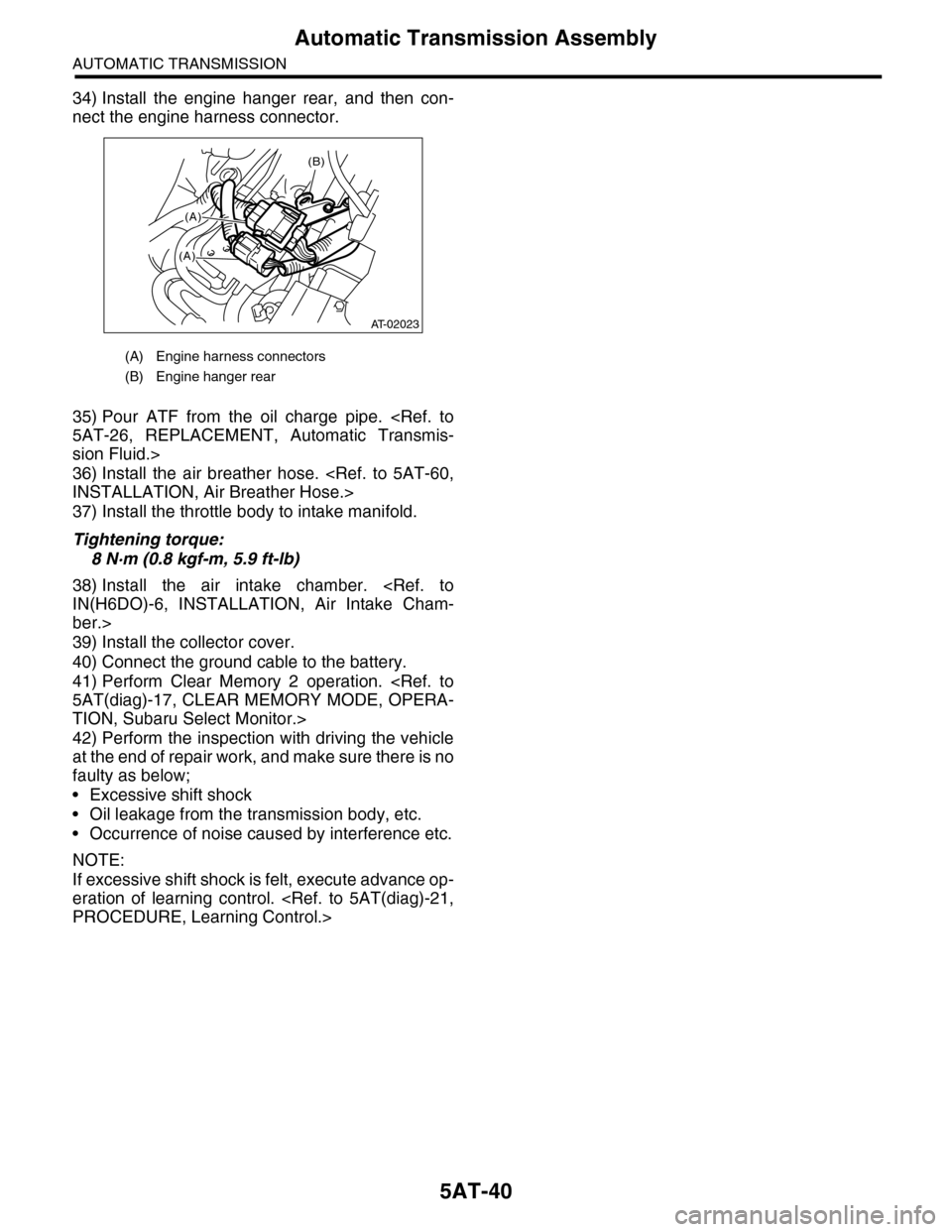
34) Install the engine hanger rear, and then con-
nect the engine harness connector.
35) Pour ATF from the oil charge pipe.
5AT-26, REPLACEMENT, Automatic Transmis-
sion Fluid.>
36) Install the air breather hose.
INSTALLATION, Air Breather Hose.>
37) Install the throttle body to intake manifold.
Tightening torque:
8 N·m (0.8 kgf-m, 5.9 ft-lb)
38) Install the air intake chamber.
IN(H6DO)-6, INSTALLATION, Air Intake Cham-
ber.>
39) Install the collector cover.
40) Connect the ground cable to the battery.
41) Perform Clear Memory 2 operation.
5AT(diag)-17, CLEAR MEMORY MODE, OPERA-
TION, Subaru Select Monitor.>
42) Perform the inspection with driving the vehicle
at the end of repair work, and make sure there is no
faulty as below;
•Excessive shift shock
•Oil leakage from the transmission body, etc.
•Occurrence of noise caused by interference etc.
NOTE:
If excessive shift shock is felt, execute advance op-
eration of learning control.
PROCEDURE, Learning Control.>
(A) Engine harness connectors
(B) Engine hanger rear
(B)
(A)
(A)
AT-02023
Page 2060 of 2453
5AT-44
Extension Case Oil Seal
AUTOMATIC TRANSMISSION
15) Pour ATF from the oil charge pipe.
Specified fluid:
SUBARU ATF (Part No. K0140Y0700)
Recommended fluid:
IDEMITSU ATF HP
CASTROL TRANSMAX J
PENNZOIL QUAKERSTATE • PENNZOIL ATF-
J
NOTE:
Use of the recommended fluid is permitted only in
regions where the specified fluid is not available.
Capacity:
Fill with the same amount of ATF as drained.
16) Check the level and leaks of the ATF.
5AT-26, Automatic Transmission Fluid.>
Page 2064 of 2453
5AT-48
Front Vehicle Speed Sensor
AUTOMATIC TRANSMISSION
6) Install the extension case.
Tightening torque:
25 N·m (2.5 kgf-m, 18 ft-lb)
7) Install the rear vehicle speed sensor.
Tightening torque:
7 N·m (0.7 kgf-m, 5.2 ft-lb)
8) Install the transmission assembly to the vehicle.
Transmission Assembly.>
9) Pour ATF from the oil charge pipe.
26, REPLACEMENT, Automatic Transmission Flu-
id.>
10) Check the level and leaks of ATF.
26, INSPECTION, Automatic Transmission Fluid.>
AT-03226
AT-03225
Page 2065 of 2453
5AT-49
Rear Vehicle Speed Sensor
AUTOMATIC TRANSMISSION
15.Rear Vehicle Speed Sensor
A: REMOVAL
1) Set the vehicle on a lift.
2) Disconnect the ground cable from battery.
3) Remove the air intake chamber.
IN(H6DO)-6, REMOVAL, Air Intake Chamber.>
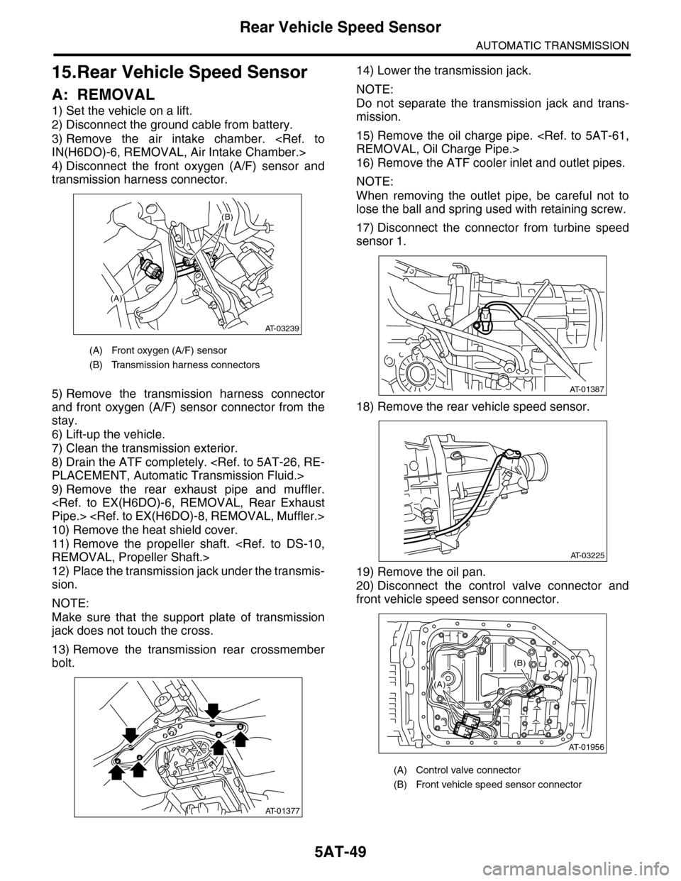
4) Disconnect the front oxygen (A/F) sensor and
transmission harness connector.
5) Remove the transmission harness connector
and front oxygen (A/F) sensor connector from the
stay.
6) Lift-up the vehicle.
7) Clean the transmission exterior.
8) Drain the ATF completely.
PLACEMENT, Automatic Transmission Fluid.>
9) Remove the rear exhaust pipe and muffler.
Pipe.>
10) Remove the heat shield cover.
11) Remove the propeller shaft.
REMOVAL, Propeller Shaft.>
12) Place the transmission jack under the transmis-
sion.
NOTE:
Make sure that the support plate of transmission
jack does not touch the cross.
13) Remove the transmission rear crossmember
bolt.
14) Lower the transmission jack.
NOTE:
Do not separate the transmission jack and trans-
mission.
15) Remove the oil charge pipe.
REMOVAL, Oil Charge Pipe.>
16) Remove the ATF cooler inlet and outlet pipes.
NOTE:
When removing the outlet pipe, be careful not to
lose the ball and spring used with retaining screw.
17) Disconnect the connector from turbine speed
sensor 1.
18) Remove the rear vehicle speed sensor.
19) Remove the oil pan.
20) Disconnect the control valve connector and
front vehicle speed sensor connector.
(A) Front oxygen (A/F) sensor
(B) Transmission harness connectors
(A)
(B)
AT-03239
AT-01377
(A) Control valve connector
(B) Front vehicle speed sensor connector
AT-01387
AT-03225
AT-01956
(B)
(A)
Page 2067 of 2453
5AT-51
Rear Vehicle Speed Sensor
AUTOMATIC TRANSMISSION
7) Install the rear vehicle speed sensor and turbine
speed sensor 1, and then fasten the harness.
Tightening torque:
7 N·m (0.7 kgf-m, 5.2 ft-lb)
8) Install a new aluminum washer and oil cooler
pipe.
Tightening torque:
40 N·m (4.1 kgf-m, 29.5 ft-lb) (ATF inlet pipe)
45 N·m (4.6 kgf-m, 33.2 ft-lb) (ATF outlet pipe)
9) Install the oil charge pipe.
STALLATION, Oil Charge Pipe.>
10) Install the transmission rear crossmember bolt.
Tightening torque:
70 N·m (7.1 kgf-m, 51.6 ft-lb)
11) Install the propeller shaft.
STALLATION, Propeller Shaft.>
12) Install the heat shield cover.
13) Install the rear exhaust pipe and muffler.
to EX(H6DO)-7, INSTALLATION, Rear Exhaust
Pipe.>
Muffler.>
14) Lower the vehicle.
15) Install the transmission connector to the stay,
and then connect the connector.
16) Install the air intake chamber.
IN(H6DO)-6, INSTALLATION, Air Intake Cham-
ber.>
17) Pour ATF from the oil charge pipe.
5AT-26, REPLACEMENT, Automatic Transmis-
sion Fluid.>
18) Check the level and leaks of ATF.
26, INSPECTION, Automatic Transmission Fluid.>
Page 2070 of 2453
5AT-54
Control Valve Body
AUTOMATIC TRANSMISSION
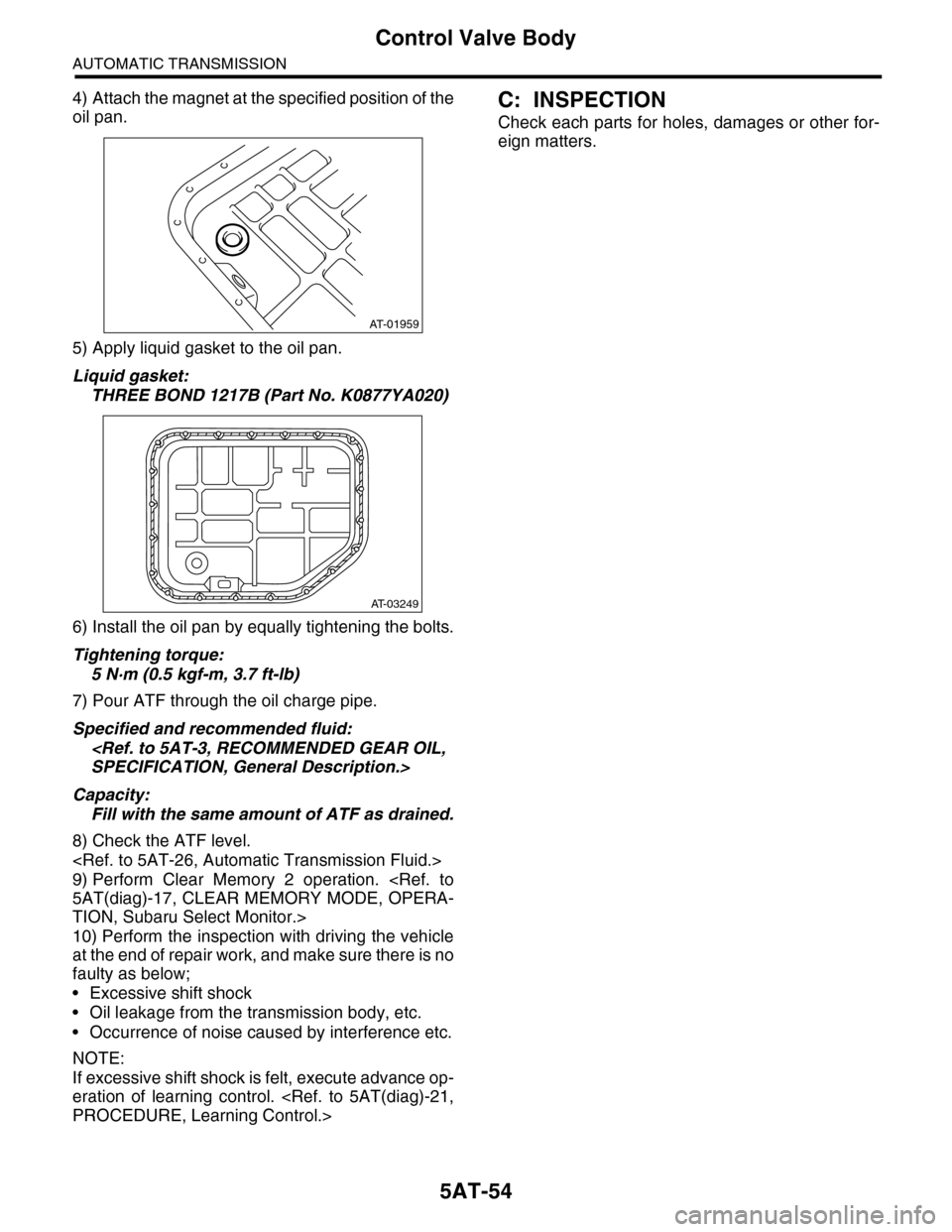
4) Attach the magnet at the specified position of the
oil pan.
5) Apply liquid gasket to the oil pan.
Liquid gasket:
THREE BOND 1217B (Part No. K0877YA020)
6) Install the oil pan by equally tightening the bolts.
Tightening torque:
5 N·m (0.5 kgf-m, 3.7 ft-lb)
7) Pour ATF through the oil charge pipe.
Specified and recommended fluid:
SPECIFICATION, General Description.>
Capacity:
Fill with the same amount of ATF as drained.
8) Check the ATF level.
9) Perform Clear Memory 2 operation.
5AT(diag)-17, CLEAR MEMORY MODE, OPERA-
TION, Subaru Select Monitor.>
10) Perform the inspection with driving the vehicle
at the end of repair work, and make sure there is no
faulty as below;
•Excessive shift shock
•Oil leakage from the transmission body, etc.
•Occurrence of noise caused by interference etc.
NOTE:
If excessive shift shock is felt, execute advance op-
eration of learning control.
PROCEDURE, Learning Control.>
C: INSPECTION
Check each parts for holes, damages or other for-
eign matters.
AT-01959
AT-03249