Page 1563 of 2453
FU(H6DO)-2
General Description
FUEL INJECTION (FUEL SYSTEMS)
1. General Description
A: SPECIFICATION
Fuel tankCapacity 64 2 (16.9 US gal, 14.1 Imp gal)
Location Rear floor bottom
Fuel pump
Ty p e I m p e l l e r
Shutoff discharge pressure550 — 850 kPa (5.61 — 8.67 kg/cm2, 79.8 — 123.3 psi)
Discharge rate155 2 (41 US gal, 34.1 Imp gal)/h or more
[12 V at 300 kPa (3.06 kg/cm2, 43.5 psi)]
Fuel filterIn-tank type
Page 1589 of 2453
FU(H6DO)-28
Front Oxygen (A/F) Sensor
FUEL INJECTION (FUEL SYSTEMS)
14.Front Oxygen (A/F) Sensor
A: REMOVAL
1) Set the vehicle on a lift.
2) Disconnect the ground cable from battery.
3) Lift-up the vehicle.
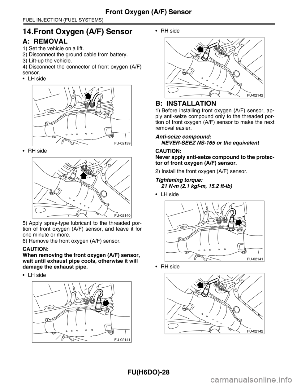
4) Disconnect the connector of front oxygen (A/F)
sensor.
•LH side
•RH side
5) Apply spray-type lubricant to the threaded por-
tion of front oxygen (A/F) sensor, and leave it for
one minute or more.
6) Remove the front oxygen (A/F) sensor.
CAUTION:
When removing the front oxygen (A/F) sensor,
wait until exhaust pipe cools, otherwise it will
damage the exhaust pipe.
•LH side
•RH side
B: INSTALLATION
1) Before installing front oxygen (A/F) sensor, ap-
ply anti-seize compound only to the threaded por-
tion of front oxygen (A/F) sensor to make the next
removal easier.
Anti-seize compound:
NEVER-SEEZ NS-165 or the equivalent
CAUTION:
Never apply anti-seize compound to the protec-
tor of front oxygen (A/F) sensor.
2) Install the front oxygen (A/F) sensor.
Tightening torque:
21 N·m (2.1 kgf-m, 15.2 ft-lb)
•LH side
•RH side
FU-02139
FU-02140
FU-02141
FU-02142
FU-02141
FU-02142
Page 1591 of 2453
FU(H6DO)-30
Rear Oxygen Sensor
FUEL INJECTION (FUEL SYSTEMS)
15.Rear Oxygen Sensor
A: REMOVAL
1) Set the vehicle on a lift.
2) Disconnect the ground cable from battery.
3) Lift-up the vehicle.
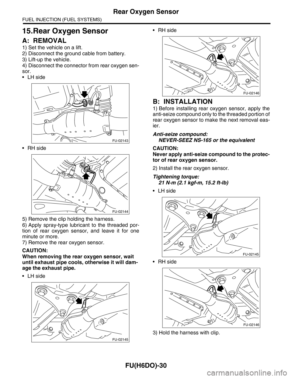
4) Disconnect the connector from rear oxygen sen-
sor.
•LH side
•RH side
5) Remove the clip holding the harness.
6) Apply spray-type lubricant to the threaded por-
tion of rear oxygen sensor, and leave it for one
minute or more.
7) Remove the rear oxygen sensor.
CAUTION:
When removing the rear oxygen sensor, wait
until exhaust pipe cools, otherwise it will dam-
age the exhaust pipe.
•LH side
•RH side
B: INSTALLATION
1) Before installing rear oxygen sensor, apply the
anti-seize compound only to the threaded portion of
rear oxygen sensor to make the next removal eas-
ier.
Anti-seize compound:
NEVER-SEEZ NS-165 or the equivalent
CAUTION:
Never apply anti-seize compound to the protec-
tor of rear oxygen sensor.
2) Install the rear oxygen sensor.
Tightening torque:
21 N·m (2.1 kgf-m, 15.2 ft-lb)
•LH side
•RH side
3) Hold the harness with clip.
FU-02143
FU-02144
FU-02145
FU-02146
FU-02145
FU-02146
Page 1611 of 2453
FU(H6DO)-50
Fuel Delivery, Return and Evaporation Lines
FUEL INJECTION (FUEL SYSTEMS)
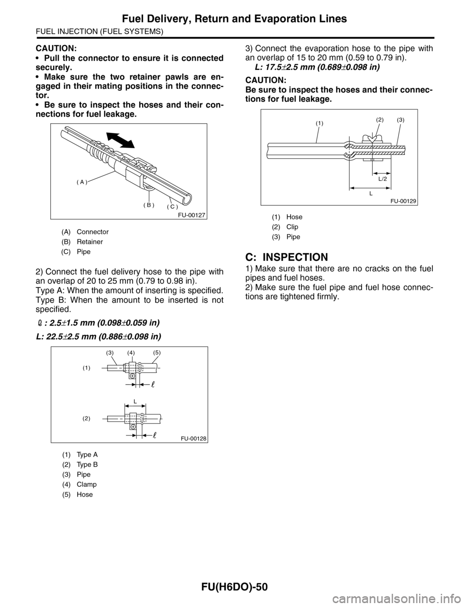
CAUTION:
•Pull the connector to ensure it is connected
securely.
•Make sure the two retainer pawls are en-
gaged in their mating positions in the connec-
tor.
•Be sure to inspect the hoses and their con-
nections for fuel leakage.
2) Connect the fuel delivery hose to the pipe with
an overlap of 20 to 25 mm (0.79 to 0.98 in).
Type A: When the amount of inserting is specified.
Type B: When the amount to be inserted is not
specified.
2: 2.5±1.5 mm (0.098±0.059 in)
L: 22.5±2.5 mm (0.886±0.098 in)
3) Connect the evaporation hose to the pipe with
an overlap of 15 to 20 mm (0.59 to 0.79 in).
L: 17.5±2.5 mm (0.689±0.098 in)
CAUTION:
Be sure to inspect the hoses and their connec-
tions for fuel leakage.
C: INSPECTION
1) Make sure that there are no cracks on the fuel
pipes and fuel hoses.
2) Make sure the fuel pipe and fuel hose connec-
tions are tightened firmly.
(A) Connector
(B) Retainer
(C) Pipe
(1) Type A
(2) Type B
(3) Pipe
(4) Clamp
(5) Hose
FU-00127
( A )
( B )( C )
(3)(4)(5)
L
(1)
(2)
FU-00128
(1) Hose
(2) Clip
(3) Pipe
FU-00129
(1)(2)
L/2
L
(3)
Page 1887 of 2453
ME(H6DO)-21
Compression
MECHANICAL
2. Compression
A: INSPECTION
CAUTION:
After warming-up, engine becomes very hot. Be
careful not to burn yourself during measure-
ment.
1) After warming-up the engine, turn the ignition
switch to OFF.
2) Make sure that the battery is fully charged.
3) Release the fuel pressure.
PRESSURE, PROCEDURE, Fuel.>
4) Remove all the spark plugs.
4, REMOVAL, Spark Plug.>
5) Check the starter motor for satisfactory perfor-
mance and operation.
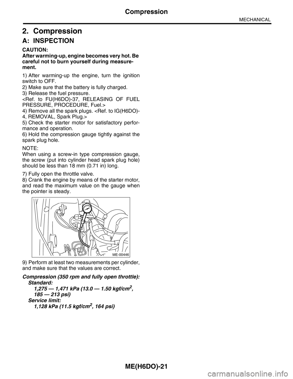
6) Hold the compression gauge tightly against the
spark plug hole.
NOTE:
When using a screw-in type compression gauge,
the screw (put into cylinder head spark plug hole)
should be less than 18 mm (0.71 in) long.
7) Fully open the throttle valve.
8) Crank the engine by means of the starter motor,
and read the maximum value on the gauge when
the pointer is steady.
9) Perform at least two measurements per cylinder,
and make sure that the values are correct.
Compression (350 rpm and fully open throttle):
Standard:
1,275 — 1,471 kPa (13.0 — 1.50 kgf/cm2,
185 — 213 psi)
Service limit:
1,128 kPa (11.5 kgf/cm2, 164 psi)
ME-00446
Page 2293 of 2453
WI-9
Basic Diagnostic Procedure
WIRING SYSTEM
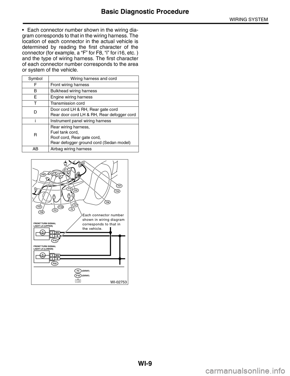
•Each connector number shown in the wiring dia-
gram corresponds to that in the wiring harness. The
location of each connector in the actual vehicle is
determined by reading the first character of the
connector (for example, a “F” for F8, “i” for i16, etc. )
and the type of wiring harness. The first character
of each connector number corresponds to the area
or system of the vehicle.
Symbol Wiring harness and cord
FFront wiring harness
BBulkhead wiring harness
EEngine wiring harness
TTransmission cord
DDoor cord LH & RH, Rear gate cord
Rear door cord LH & RH, Rear defogger cord
iInstrument panel wiring harness
R
Rear wiring harness,
Fuel tank cord,
Roof cord, Rear gate cord,
Rear defogger ground cord (Sedan model)
AB Airbag wiring harness
F23
F98F21
F58
F100F5
F27
F47
F34F19F22
F96
WI-02753
Each connector number shown in wiring diagram corresponds to that in the vehicle.
F19
FRONT TURN SIGNAL LIGHT LH (UPPER)
BG2B1
F22
FRONT TURN SIGNAL LIGHT LH (LOWER)
BG3B2
(GRAY)F3(GRAY)F19
12