2009 SUBARU TRIBECA air filter
[x] Cancel search: air filterPage 1866 of 2453
LU(H6DO)-17
General Diagnostics Table
LUBRICATION
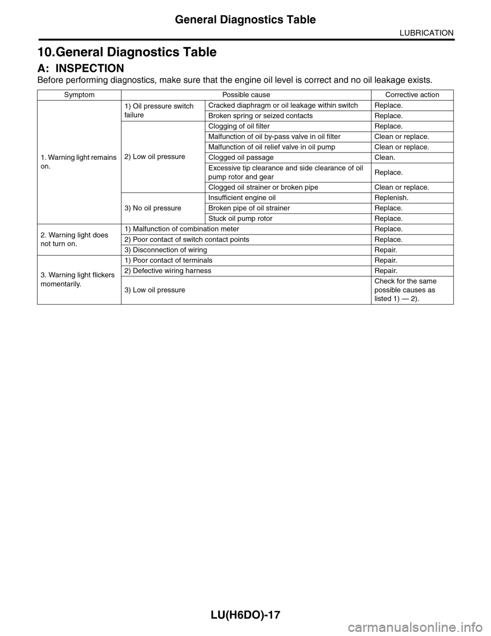
10.General Diagnostics Table
A: INSPECTION
Before performing diagnostics, make sure that the engine oil level is correct and no oil leakage exists.
Symptom Possible cause Corrective action
1. Warning light remains
on.
1) Oil pressure switch
failure
Cracked diaphragm or oil leakage within switch Replace.
Broken spring or seized contacts Replace.
2) Low oil pressure
Clogging of oil filter Replace.
Malfunction of oil by-pass valve in oil filter Clean or replace.
Malfunction of oil relief valve in oil pump Clean or replace.
Clogged oil passage Clean.
Excessive tip clearance and side clearance of oil
pump rotor and gearReplace.
Clogged oil strainer or broken pipe Clean or replace.
3) No oil pressure
Insufficient engine oil Replenish.
Broken pipe of oil strainer Replace.
Stuck oil pump rotor Replace.
2. Warning light does
not turn on.
1) Malfunction of combination meter Replace.
2) Poor contact of switch contact points Replace.
3) Disconnection of wiring Repair.
3. Warning light flickers
momentarily.
1) Poor contact of terminals Repair.
2) Defective wiring harness Repair.
3) Low oil pressure
Check for the same
possible causes as
listed 1) — 2).
Page 1921 of 2453
ME(H6DO)-55
Camshaft
MECHANICAL
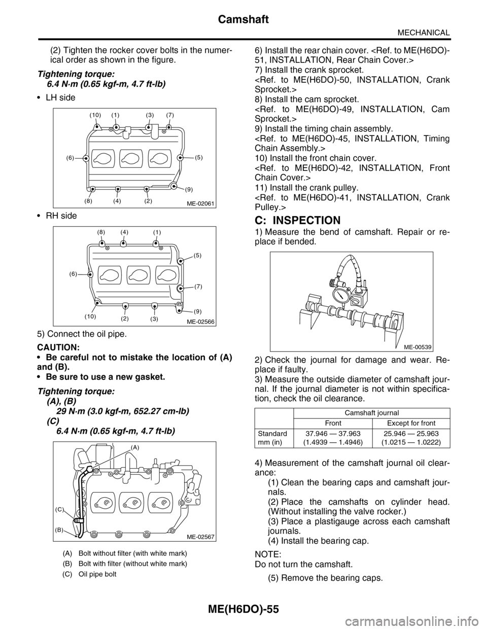
(2) Tighten the rocker cover bolts in the numer-
ical order as shown in the figure.
Tightening torque:
6.4 N·m (0.65 kgf-m, 4.7 ft-lb)
•LH side
•RH side
5) Connect the oil pipe.
CAUTION:
•Be careful not to mistake the location of (A)
and (B).
•Be sure to use a new gasket.
Tightening torque:
(A), (B)
29 N·m (3.0 kgf-m, 652.27 cm-lb)
(C)
6.4 N·m (0.65 kgf-m, 4.7 ft-lb)
6) Install the rear chain cover.
7) Install the crank sprocket.
8) Install the cam sprocket.
9) Install the timing chain assembly.
10) Install the front chain cover.
11) Install the crank pulley.
C: INSPECTION
1) Measure the bend of camshaft. Repair or re-
place if bended.
2) Check the journal for damage and wear. Re-
place if faulty.
3) Measure the outside diameter of camshaft jour-
nal. If the journal diameter is not within specifica-
tion, check the oil clearance.
4) Measurement of the camshaft journal oil clear-
ance:
(1) Clean the bearing caps and camshaft jour-
nals.
(2) Place the camshafts on cylinder head.
(Without installing the valve rocker.)
(3) Place a plastigauge across each camshaft
journals.
(4) Install the bearing cap.
NOTE:
Do not turn the camshaft.
(5) Remove the bearing caps.
(A) Bolt without filter (with white mark)
(B) Bolt with filter (without white mark)
(C) Oil pipe bolt
ME-02061(2)
(7)(3)(1)(10)
(6)
(8)(4)
(5)
(9)
ME-02566
(8)(4)(1)
(5)
(7)
(9)(3)(2)
(6)
(10)
ME-02567
(A)
(C)
(B)
Camshaft journal
Front Except for front
Standard
mm (in)
37.946 — 37.963
(1.4939 — 1.4946)
25.946 — 25.963
(1.0215 — 1.0222)
ME-00539
Page 1986 of 2453
PM-3
Schedule
PERIODIC MAINTENANCE SERVICES
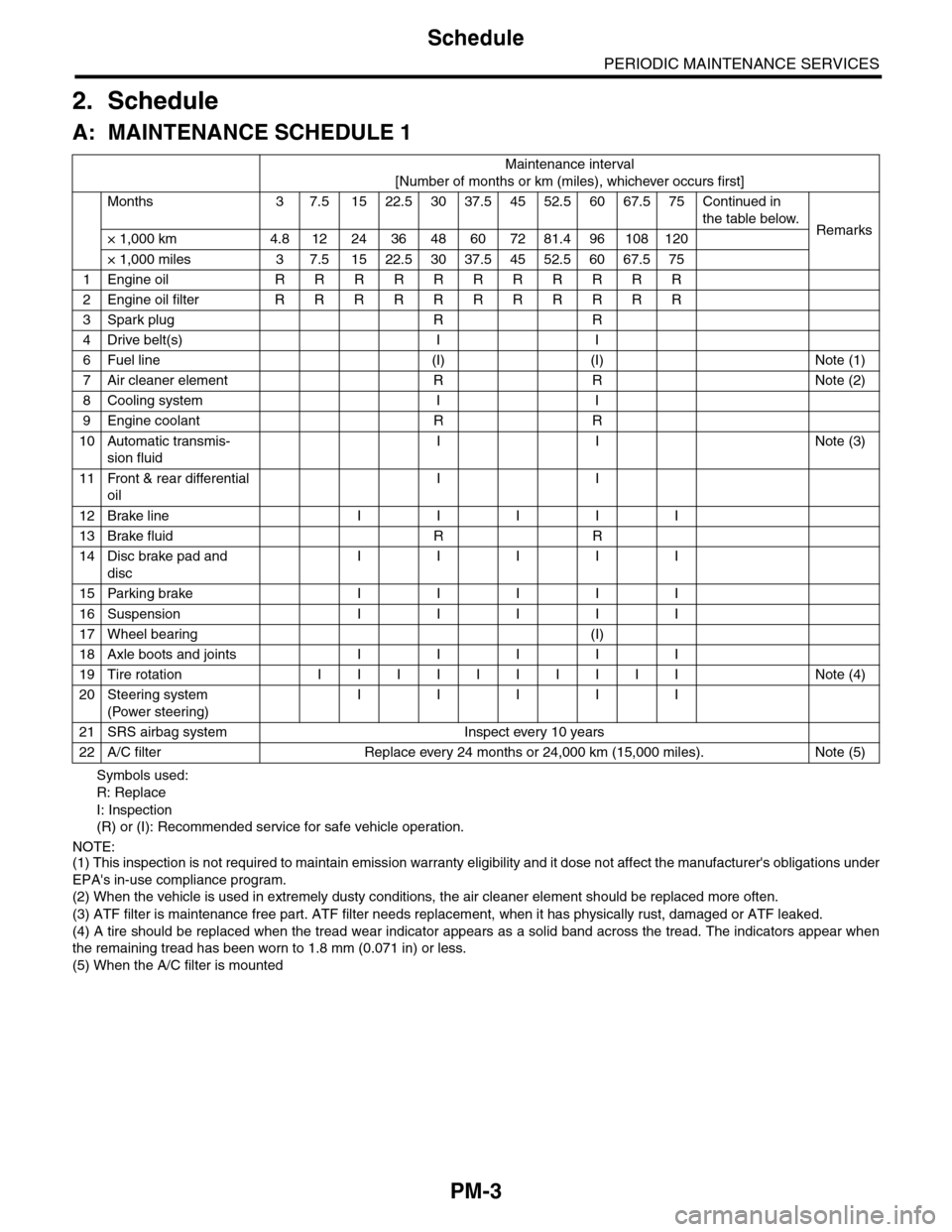
2. Schedule
A: MAINTENANCE SCHEDULE 1
Symbols used:
R: Replace
I: Inspection
(R) or (I): Recommended service for safe vehicle operation.
NOTE:(1) This inspection is not required to maintain emission warranty eligibility and it dose not affect the manufacturer's obligations under
EPA's in-use compliance program.
(2) When the vehicle is used in extremely dusty conditions, the air cleaner element should be replaced more often.
(3) ATF filter is maintenance free part. ATF filter needs replacement, when it has physically rust, damaged or ATF leaked.
(4) A tire should be replaced when the tread wear indicator appears as a solid band across the tread. The indicators appear when
the remaining tread has been worn to 1.8 mm (0.071 in) or less.
(5) When the A/C filter is mounted
Maintenance interval
[Number of months or km (miles), whichever occurs first]
Months 3 7.51522.53037.54552.56067.575Continued in
the table below.Remarks× 1,000 km 4.8 12 24 36 48 60 72 81.4 96 108 120
× 1,000 miles 3 7.5 15 22.5 30 37.5 45 52.5 60 67.5 75
1Engine oil R R R R R R R R R R R
2Engine oil filter R R R R R R R R R R R
3Spark plug R R
4Drive belt(s) I I
6Fuel line (I) (I) Note (1)
7Air cleaner element R R Note (2)
8Cooling system I I
9Engine coolant R R
10 Automatic transmis-
sion fluid
I I Note (3)
11 Front & rear differential
oil
I I
12 Brake line I I I I I
13 Brake fluid R R
14 Disc brake pad and
disc
I I I I I
15 Parking brake I I I I I
16 Suspension I I I I I
17 Wheel bearing (I)
18 Axle boots and joints I I I I I
19 Tire rotation I I I I I I I I I I Note (4)
20 Steering system
(Power steering)
I I I I I
21 SRS airbag system Inspect every 10 years
22 A/C filter Replace every 24 months or 24,000 km (15,000 miles). Note (5)
Page 1987 of 2453
PM-4
Schedule
PERIODIC MAINTENANCE SERVICES
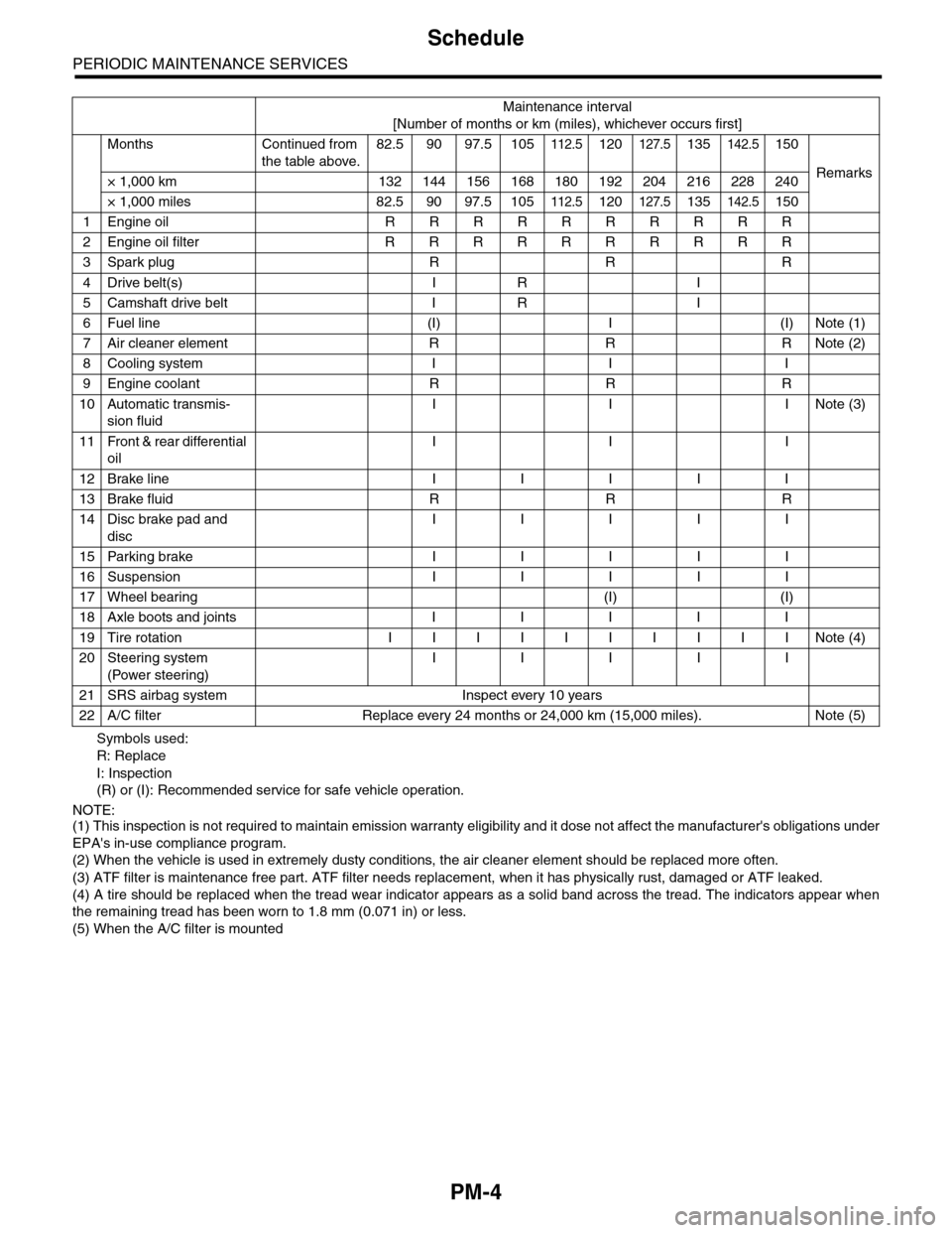
Symbols used:
R: Replace
I: Inspection
(R) or (I): Recommended service for safe vehicle operation.
NOTE:(1) This inspection is not required to maintain emission warranty eligibility and it dose not affect the manufacturer's obligations under
EPA's in-use compliance program.
(2) When the vehicle is used in extremely dusty conditions, the air cleaner element should be replaced more often.
(3) ATF filter is maintenance free part. ATF filter needs replacement, when it has physically rust, damaged or ATF leaked.
(4) A tire should be replaced when the tread wear indicator appears as a solid band across the tread. The indicators appear when
the remaining tread has been worn to 1.8 mm (0.071 in) or less.
(5) When the A/C filter is mounted
Maintenance interval
[Number of months or km (miles), whichever occurs first]
Months Continued from
the table above.
82.5 90 97.5 105112.5120127.5135142.5150
Remarks× 1,000 km 132 144 156 168 180 192 204 216 228 240
× 1,000 miles 82.5 90 97.5 105112.5120127.5135142.5150
1Engine oil R R R R R R R R R R
2Engine oil filter R R R R R R R R R R
3Spark plug R R R
4Drive belt(s) I R I
5Camshaft drive belt I R I
6Fuel line (I) I (I) Note (1)
7Air cleaner element R R R Note (2)
8Cooling system I I I
9Engine coolant R R R
10 Automatic transmis-
sion fluid
I I INote (3)
11 Front & rear differential
oil
I I I
12 Brake line I I I I I
13 Brake fluid R R R
14 Disc brake pad and
disc
I I I I I
15 Parking brake I I I I I
16 Suspension I I I I I
17 Wheel bearing (I) (I)
18 Axle boots and joints I I I I I
19 Tire rotation I I I I I I I I I I Note (4)
20 Steering system
(Power steering)
I I I I I
21 SRS airbag system Inspect every 10 years
22 A/C filter Replace every 24 months or 24,000 km (15,000 miles). Note (5)
Page 2092 of 2453
5AT-76
Converter Case
AUTOMATIC TRANSMISSION
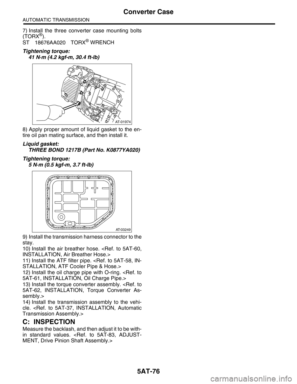
7) Install the three converter case mounting bolts
(TORX®).
ST 18676AA020 TORX® WRENCH
Tightening torque:
41 N·m (4.2 kgf-m, 30.4 ft-lb)
8) Apply proper amount of liquid gasket to the en-
tire oil pan mating surface, and then install it.
Liquid gasket:
THREE BOND 1217B (Part No. K0877YA020)
Tightening torque:
5 N·m (0.5 kgf-m, 3.7 ft-lb)
9) Install the transmission harness connector to the
stay.
10) Install the air breather hose.
11) Install the ATF filter pipe.
12) Install the oil charge pipe with O-ring.
13) Install the torque converter assembly.
sembly.>
14) Install the transmission assembly to the vehi-
cle.
C: INSPECTION
Measure the backlash, and then adjust it to be with-
in standard values.
AT-01974
AT-03249
Page 2097 of 2453
5AT-81
Drive Pinion Shaft Assembly
AUTOMATIC TRANSMISSION
32.Drive Pinion Shaft Assembly
A: REMOVAL
1) Remove the transmission assembly from vehicle
body.
2) Pull out the torque converter assembly.
3) Remove the transmission harness connector
from stay.
4) Disconnect the air breather hose.
5) Remove the oil charge pipe.
6) Remove the ATF filter inlet and outlet pipes.
7) Separate the converter case and transmission
case.
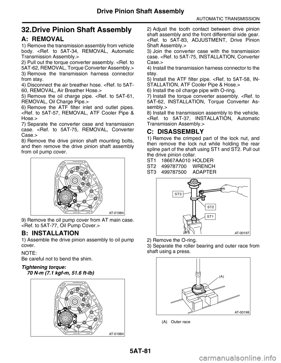
8) Remove the drive pinion shaft mounting bolts,
and then remove the drive pinion shaft assembly
from oil pump cover.
9) Remove the oil pump cover from AT main case.
B: INSTALLATION
1) Assemble the drive pinion assembly to oil pump
cover.
NOTE:
Be careful not to bend the shim.
Tightening torque:
70 N·m (7.1 kgf-m, 51.6 ft-lb)
2) Adjust the tooth contact between drive pinion
shaft assembly and the front differential side gear.
3) Join the converter case with the transmission
case.
4) Install the transmission harness connector to the
stay.
5) Install the ATF filter pipe.
6) Install the oil charge pipe with O-ring.
7) Install the torque converter assembly.
sembly.>
8) Install the transmission assembly to the vehicle.
C: DISASSEMBLY
1) Remove the crimped part of the lock nut, and
then remove the lock nut while holding the rear
spline part of the shaft using ST1 and ST2. Pull out
the drive pinion collar.
ST1 18667AA010 HOLDER
ST2 499787700 WRENCH
ST3 499787500 ADAPTER
2) Remove the O-ring.
3) Separate the roller bearing and outer race from
shaft using a press.
AT-01984
AT-01984
(A) Outer race
AT-00197
ST1
ST3
ST2
AT-00198
(A)
Page 2107 of 2453
5AT-91
AT Main Case
AUTOMATIC TRANSMISSION
34.AT Main Case
A: REMOVAL
1) Remove the transmission assembly from vehicle
body.
2) Pull out the torque converter assembly.
3) Remove the transmission harness connector
from stay.
4) Disconnect the air breather hose.
5) Remove the oil charge pipe.
6) Remove the ATF filter inlet and outlet pipes.
7) Remove the extension case.
8) Remove the center differential carrier.
9) Remove the reduction driven gear.
10) Separate the converter case from the transmis-
sion case.
11) Remove the control valve body.
12) Remove the oil pump cover.
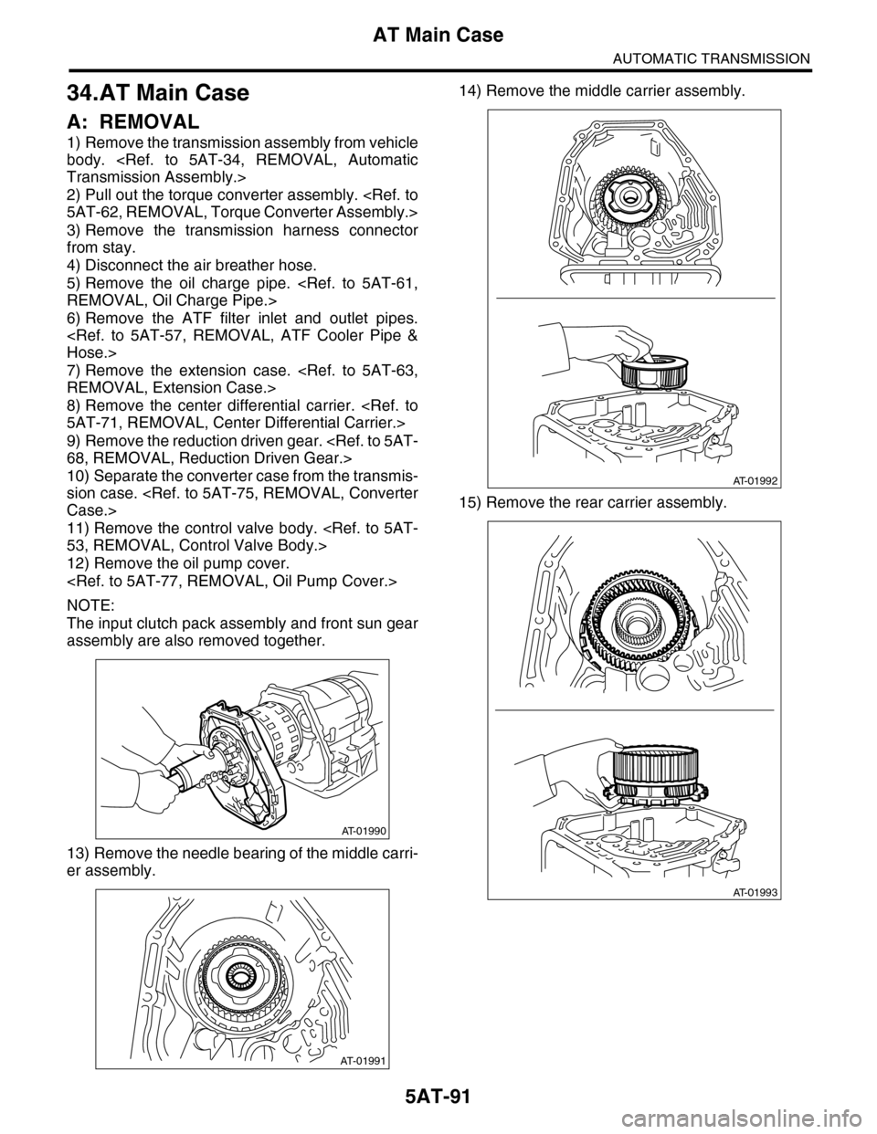
NOTE:
The input clutch pack assembly and front sun gear
assembly are also removed together.
13) Remove the needle bearing of the middle carri-
er assembly.
14) Remove the middle carrier assembly.
15) Remove the rear carrier assembly.
AT-01990
AT-01991
AT-01992
AT-01993
Page 2113 of 2453
5AT-97
AT Main Case
AUTOMATIC TRANSMISSION
24) Install the extension case.
25) Install the control valve body.
26) Install the converter case assembly to the
transmission case assembly.
27) Install the air breather hose.
28) Install the ATF filter pipe.
29) Install the oil charge pipe together with an O-
ring.
30) Install the torque converter assembly.
sembly.>
31) Install the transmission assembly to the vehi-
cle.
32) Perform Clear Memory 2 operation.
TION, Subaru Select Monitor.>
33) Perform the inspection with driving the vehicle
at the end of repair work, and make sure there is no
faulty as below;
•Excessive shift shock
•Oil leakage from the transmission body, etc.
•Occurrence of noise caused by interference etc.
NOTE:
If excessive shift shock is felt, execute advance op-
eration of learning control.
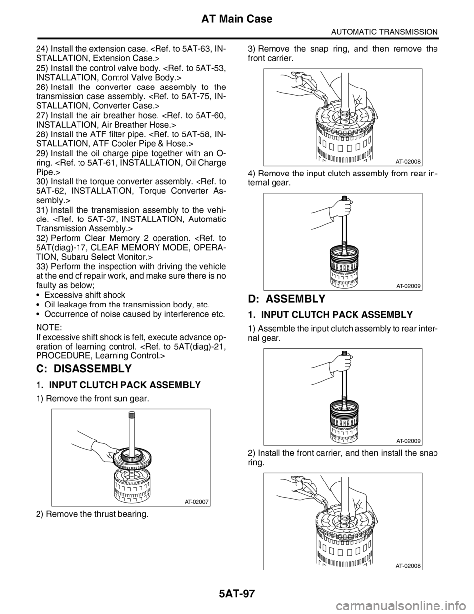
C: DISASSEMBLY
1. INPUT CLUTCH PACK ASSEMBLY
1) Remove the front sun gear.
2) Remove the thrust bearing.
3) Remove the snap ring, and then remove the
front carrier.
4) Remove the input clutch assembly from rear in-
ternal gear.
D: ASSEMBLY
1. INPUT CLUTCH PACK ASSEMBLY
1) Assemble the input clutch assembly to rear inter-
nal gear.
2) Install the front carrier, and then install the snap
ring.
AT-02007
AT-02008
AT-02009
AT-02009
AT-02008