2009 SUBARU TRIBECA fog light
[x] Cancel search: fog lightPage 246 of 2453

EI-4
General Description
EXTERIOR/INTERIOR TRIM
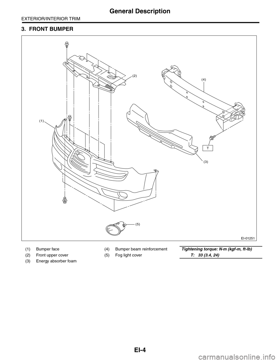
3. FRONT BUMPER
(1) Bumper face (4) Bumper beam reinforcementTightening torque: N·m (kgf-m, ft-lb)
(2) Front upper cover (5) Fog light coverT: 33 (3.4, 24)
(3) Energy absorber foam
EI-01251
(2)
(1)
(5)
(3)
(4)
T
Page 263 of 2453

EI-21
Front Bumper
EXTERIOR/INTERIOR TRIM
6. Front Bumper
A: REMOVAL
1. FRONT BUMPER FACE
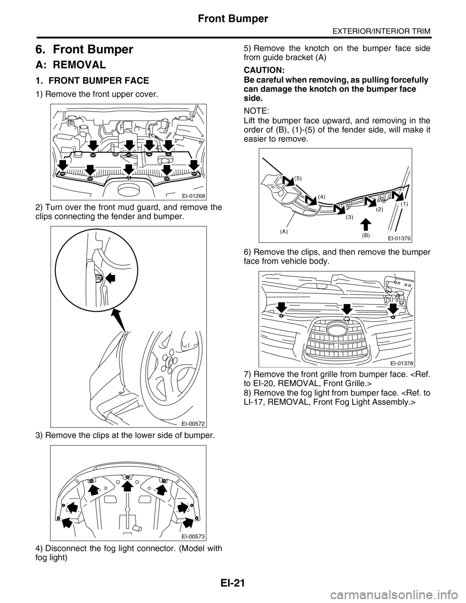
1) Remove the front upper cover.
2) Turn over the front mud guard, and remove the
clips connecting the fender and bumper.
3) Remove the clips at the lower side of bumper.
4) Disconnect the fog light connector. (Model with
fog light)
5) Remove the knotch on the bumper face side
from guide bracket (A)
CAUTION:
Be careful when removing, as pulling forcefully
can damage the knotch on the bumper face
side.
NOTE:
Lift the bumper face upward, and removing in the
order of (B), (1)-(5) of the fender side, will make it
easier to remove.
6) Remove the clips, and then remove the bumper
face from vehicle body.
7) Remove the front grille from bumper face.
8) Remove the fog light from bumper face.
EI-01268
EI-00572
EI-00573
EI-01379
(1)(2)
(3)
(4)
(5)
(B)(A)
EI-01378
Page 317 of 2453

GW-22
Rear Gate Glass
GLASS/WINDOWS/MIRRORS
15.Rear Gate Glass
A: REMOVAL
1) Remove the rear wiper motor.
2) Disconnect the electrical connectors from rear
defogger terminal.
3) Remove the glass in the same procedure as for
windshield glass.
B: INSTALLATION
1) Mount the fastener on the body.
2) Install the dam rubber.
3) Cut off the cartridge nozzle tip as shown and set
it in sealant gun.
4) Apply adhesive in the same procedure as for
windshield glass.
5) Insert the glass clip pin into rear gate hole, push
on the area around the clip pin to secure it, and
then push lightly all around the area to seal it.
(1) Glass
(2) Spacer
(3) Adhesive
(4) Fastener
(5) 4 mm (0.15 in)
(6) 8 mm (0.31 in)
(7) 10 mm (0.39 in)
(8) 5.5 mm (0.22 in)
Page 441 of 2453

IDI-2
General Description
INSTRUMENTATION/DRIVER INFO
1. General Description
A: SPECIFICATION
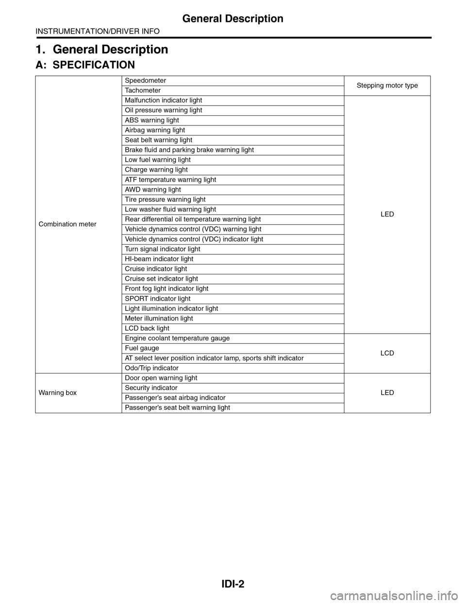
Combination meter
SpeedometerStepping motor typeTa c h o m e t e r
Malfunction indicator light
LED
Oil pressure warning light
ABS warning light
Airbag warning light
Seat belt warning light
Brake fluid and parking brake warning light
Low fuel warning light
Charge warning light
AT F t e m p e r a t u r e w a r n i n g l i g h t
AW D war n in g l i gh t
Tire pressure warning light
Low washer fluid warning light
Rear differential oil temperature warning light
Ve h i c l e d y n a m i c s c o n t r o l ( V D C ) w a r n i n g l i g h t
Ve h i c l e d y n a m i c s c o n t r o l ( V D C ) i n d i c a t o r l i g h t
Tu r n s i g n a l i n d i c a t o r l i g h t
HI-beam indicator light
Cruise indicator light
Cruise set indicator light
Fr o nt fog li g ht i nd i ca to r li g ht
SPORT indicator light
Light illumination indicator light
Meter illumination light
LCD back light
Engine coolant temperature gauge
LCDFuel gauge
AT s e l e c t l e v e r p o s i t i o n i n d i c a t o r l a m p , s p o r t s s h i f t i n d i c a t o r
Odo/Trip indicator
Wa r ni n g b ox
Door open warning light
LEDSecurity indicator
Passenger’s seat airbag indicator
Passenger’s seat belt war ning light
Page 465 of 2453

LAN(diag)-9
Control Module I/O Signal
LAN SYSTEM (DIAGNOSTICS)
5. Control Module I/O Signal
A: ELECTRICAL SPECIFICATION
DescriptionConnec-
tor No.
Te r m i n a l
No.
Signal (V)
NoteIgnition switch ON
(Engine OFF)
System control power
supplyB281 C2 10 — 13 V Always
Backup power supply B280 B7 10 — 13 V Always
Ignition power supply i84 A1 10 — 13 V Ignition ON
ACC power supply i84 A24 10 — 13 V AC C ON
Ground
i84 A21
0 V AlwaysB281 C9
B281 C8
B280 B22
Key war ning switch B281 C7 10 — 13 V When ignition key inser ted
Stop light switch B281 C23 10 — 13 V When brake pedal depressed
Illumination control switch
(Bright switch)i84 A30 10 — 13 V (at dimmer ON)Cancel the extinction of the clock and
audio illumination
Illumination control switch i84 A30 10 — 13 V (at dimmer ON) Extinct the clock and audio illumination
Illumination volume (Vi1) i84 A10 4.5 — 5.5 V Small light ON
Illumination volume (Vi2) i84 A2 0.5 — 4.5 V —
Illumination volume (Vi3) i84 A25 0 V Ground circuit
Illumination output i84 A5 10 — 13 V Small light ON
Fr o nt fog li g ht in p ut B 28 1 C1 7 1 0 — 1 3 V Fr o nt fo g l i gh t ON
Door switch input Driver’s
seati84 A19 Less than 1 V (10 — 13 V at OFF) Driver’s door open (ON)
Door switch input Passen-
ger’s seati84 A32 Less than 1 V (10 — 13 V at OFF) Passenger’s door open (ON)
Door switch input Rear RH
seati84 A18 Less than 1 V (10 — 13 V at OFF) Rear RH door open (ON)
Door switch input Rear LH
seati84 A31 Less than 1 V (10 — 13 V at OFF) Rear LH door open (ON)
Door switch
Tr u n k / R e a r g a t ei84 A17 Less than 1 V (10 — 13 V at OFF) Trunk/Rear gate open (ON)
Manual switch (LOCK) i84 A15 Less than 1 ΩDoor lock switch ON
CS-00273
71928
61827
51741626152514241312231122
3102921
1820
B281side
72030
619291828
51741627152614132512241123
3102922
1821
B280side
82335
722342162033
51932183117301615291428
41327
312261121025
1924
i84side
Page 466 of 2453

LAN(diag)-10
Control Module I/O Signal
LAN SYSTEM (DIAGNOSTICS)
Manual switch (UNLOCK) i84 A29 Less than 1 ΩDoor unlock switch ON
Door lock power supply i84 A34 10 — 13 V Always
All door lock output i84 A7 10 — 13 V Manual lock switch, door key switch ON
Driver’s door UNLOCK
outputi84 A23 10 — 13 V Driver’s seat unlock signal ON
All door UNLOCK output i84 A8 10 — 13 V ALL door unlock signals ON
Rear gate UNLOCK out-
puti84 A22 10 — 13 VWhen rear gate release switch ON with
all seats unlocked
Rear gate release switch B281 C22 0 V Rear gate release switch ON
Key/shift lock power sup-
plyB281 C1 10 — 13 V Always
Shift lock output B280 B6 10 — 13 VIgnition switch ON, shift position “P”
range, foot brake ON (Only AT)
Key locking output B280 B5 10 — 13 VOther than “P” range, ignition switch
ON
Wiper deicer switch i84 A14 0 V Wiper deicer switch ON
Wiper deicer relay output B280 B14 0 V Wiper deicer relay ON
Rear defogger switch i84 A28 0 V Rear defogger switch ON
Rear defogger relay out-
putB281 B16 0 V Rear defogger relay ON
Shift switch (ON) B281 C26 0 V At Manual mode
Shift switch (UP) B281 C15 0 V At Manual mode UP
Shift switch (DOWN) B281 C25 0 V At Manual mode DOWN
Shift button switch B281 C24 0 VWhen shift lever release button is oper-
ated
P range switch B281 C13 0 V Shift range P position
Impact sensor B281 C5 8 V or moreImpact sensor ON (Model with impact
sensor)
Fuel level sensor B281 C19 0 — 102.3 Ω
Resistance differs according to the fuel
level (displays resistance combining
level gauge main and sub)
Ambient temperature sen-
sor
B281 C3 0.5 — 4.5 V SIG
B281 C10 0 V GND
Seat belt switch (driver’s
seat)i84 A4 0 V When driver’s seat belt is worn
Seat belt switch (Passen-
ger’s seat)i84 A13 0 V When passenger’s seat belt is worn
Seat belt warning light
(driver’s seat)i84 A20 0 V When driver’s seat belt is worn
Seat belt warning light
(Passenger’s seat)B280 C27 0 V When passenger’s seat belt is worn
Rear wiper switch (ON) B281 C6 0 V Rear wiper switch ON
Rear wiper switch (INT) B281 C18 0 V Rear wiper switch ON
Rear washer switch B281 C27 0 V Rear washer switch ON
Rear wiper power supply B280 B21 10 — 13 V Ignition switch ON
Rear wiper ON output B280 B1 10 — 13 V Rear wiper switch ON
Rear wiper return B280B8 0 VAt wiper reversingB1 — B8 0 V
Room lamp output B280 B3 0 VWhen LOCK, UNLOCK with keyless
entry
Map lamp output B280D2 0 V When using map lamp
D9 0 V When using map lamp
DescriptionConnec-
tor No.
Te r m i n a l
No.
Signal (V)
NoteIgnition switch ON
(Engine OFF)
Page 470 of 2453

LAN(diag)-14
Subaru Select Monitor
LAN SYSTEM (DIAGNOSTICS)
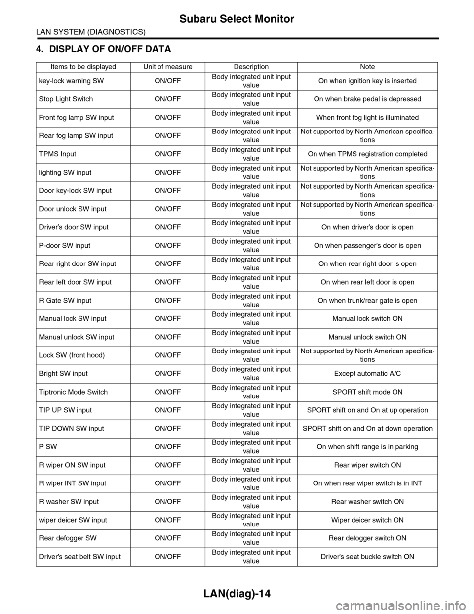
4. DISPLAY OF ON/OFF DATA
Items to be displayed Unit of measure Description Note
key-lock warning SW ON/OFFBody integrated unit input
valueOn when ignition key is inserted
Stop Light Switch ON/OFFBody integrated unit input
valueOn when brake pedal is depressed
Fr o nt fog la mp S W i n pu t O N/O FFBody integrated unit input
valueWhen front fog light is illuminated
Rear fog lamp SW input ON/OFFBody integrated unit input
value
Not supported by North American specifica-
tions
TPMS Input ON/OFFBody integrated unit input
valueOn when TPMS registration completed
lighting SW input ON/OFFBody integrated unit input
value
Not supported by North American specifica-
tions
Door key-lock SW input ON/OFFBody integrated unit input
value
Not supported by North American specifica-
tions
Door unlock SW input ON/OFFBody integrated unit input
value
Not supported by North American specifica-
tions
Driver’s door SW input ON/OFFBody integrated unit input
valueOn when driver’s door is open
P-door SW input ON/OFFBody integrated unit input
valueOn when passenger’s door is open
Rear right door SW input ON/OFFBody integrated unit input
valueOn when rear right door is open
Rear left door SW input ON/OFFBody integrated unit input
valueOn when rear left door is open
R Gate SW input ON/OFFBody integrated unit input
valueOn when trunk/rear gate is open
Manual lock SW input ON/OFFBody integrated unit input
valueManual lock switch ON
Manual unlock SW input ON/OFFBody integrated unit input
valueManual unlock switch ON
Lock SW (front hood) ON/OFFBody integrated unit input
value
Not supported by North American specifica-
tions
Bright SW input ON/OFFBody integrated unit input
valueExcept automatic A/C
Tiptronic Mode Switch ON/OFFBody integrated unit input
valueSPORT shift mode ON
TIP UP SW input ON/OFFBody integrated unit input
valueSPORT shift on and On at up operation
TIP DOWN SW input ON/OFFBody integrated unit input
valueSPORT shift on and On at down operation
P SW ON/OFFBody integrated unit input
valueOn when shift range is in parking
R wiper ON SW input ON/OFFBody integrated unit input
valueRear wiper switch ON
R wiper INT SW input ON/OFFBody integrated unit input
valueOn when rear wiper switch is in INT
R washer SW input ON/OFFBody integrated unit input
valueRear washer switch ON
wiper deicer SW input ON/OFFBody integrated unit input
valueWiper deicer switch ON
Rear defogger SW ON/OFFBody integrated unit input
valueRear defogger switch ON
Driver’s seat belt SW input ON/OFFBody integrated unit input
valueDriver’s seat buckle switch ON
Page 471 of 2453

LAN(diag)-15
Subaru Select Monitor
LAN SYSTEM (DIAGNOSTICS)
P seatbelt SW input ON/OFFBody integrated unit input
valuePa s se ng e r ’s se at bu ckl e sw it c h ON
Fr wi pe r in p ut O N/O FFBody integrated unit input
valueOn when front wiper is operating
Registration SW input ON/OFFBody integrated unit input
value
Not supported by North American specifica-
tions
Identification SW input ON/OFFBody integrated unit input
value
Not supported by North American specifica-
tions
R defogger output ON/OFFBody integrated unit output
valueOn when rear defogger relay is operating
Door lock actuator LOCK
outputON/OFFBody integrated unit output
valueOn when lock signal is output
All seat UNLOCK output ON/OFFBody integrated unit output
valueOn when unlock signal is output
D-seat UNLOCK output ON/OFFBody integrated unit output
valueOn when unlock signal is output
R gate/trunk UNLK output ON/OFFBody integrated unit output
value
On when rear gate/trunk unlock signal is
output
Double lock output ON/OFFBody integrated unit output
value
Not supported by North American specifica-
tions
R wiper output ON/OFFBody integrated unit output
valueOn when rear wiper is operating
Shift Lock Solenoid ON/OFFBody integrated unit output
valueOn when shift lock solenoid is operating
Key locking output ON/OFFBody integrated unit output
valueOn when key lock solenoid is operating
wiper deicer SW input ON/OFFBody integrated unit output
valueOn when wiper deicer is operating
Starter cutting output ON/OFFBody integrated unit output
value
Not supported by North American specifica-
tions
Hazard Output ON/OFFBody integrated unit output
value
On when keyless lock/unlock signal is
received (when keyless switch connector is
removed)
Keyless Buzzer Output ON/OFFBody integrated unit output
value
On when keyless lock/unlock signal is
received (when keyless switch connector is
removed)
Horn Output ON/OFFBody integrated unit output
valueOn when security warning is operating
Siren Output ON/OFFBody integrated unit output
value
On when siren is installed, customize set-
tings are enabled, and security warning is
operating
D-belt warning light O/P ON/OFFBody integrated unit output
value
On when Ignition switch is turned to ON,
and buckle switch is turned off
P-belt warning light O/P ON/OFFBody integrated unit output
value
On when Ignition switch is turned to ON,
occupant is seated, and buckle switch is
turned off
Illumination lamp O/P ON/OFFBody integrated unit output
valueOn when illumination is illuminated
Room lamp output ON/OFFBody integrated unit output
value
On when keyless lock/unlock signal is
received (when keyless switch connector is
removed)
key illumi. lamp o/p ON/OFFBody integrated unit output
valueOn when key illumination light is illuminated
R fog light output ON/OFFBody integrated unit output
value
Not supported by North American specifica-
tions
R fog lamp monitor ON/OFFBody integrated unit output
value
Not supported by North American specifica-
tions
Items to be displayed Unit of measure Description Note