Page 225 of 271

Breakdown assistance
224
The vehicle tool kit and the lifting jack*, on which a sign is affixed, are stowed in a box in the luggage compartment
⇒page 223, fig. 182
; there is also space here for the
detachable ball head of the towing devi
ce*. The box is secured with a strap.
The vehicle tool kit contains the following
parts (depending on equipment fitted):
•
Wire clamps for removing the full wheel trims,
•
Wheel wrench*,
•
To w i n g e y e ,
•
Adapter for the wheel bolts lock*,
•
Replacement bulb set*
15),
•
To r x s c r e w d r i v e r.
Before placing the lifting jack back in its storage area, screw in the arm of the lifting jack fully.
WARNING
•
The factory-supplied lifting jack is only intended for your model of vehicle.
On no account attempt to lift a heavier vehicle or other loads - risk of injury!•
Ensure that the vehicle tool kit is safely attached in the luggage compart-
ment.
Note
Ensure that the box is always secured with the strap.Tyre repair kitThe tyre repair kit is intended for the repair
of minor tyre defects. The tyre repair kit
contains a compressor, inflation bottle,
operating instructions and accessories.
The repair with the tyre repair kit is
not at all intended to replace
a permanent repair
on the tyre, this repair only serves to reach the next specialist garage. The repair can be undertaken on the vehicle immediately.
Please read the attached instructions care-
fully before the repair.
The tyre repair kit is located in
a box in the luggage compartment
⇒page 223,
fig. 182
.
Spare wheel*The spare wheel is stowed in the luggage compartment in the area below the variable loading floor* and is secured with a special screw
⇒fig. 183
.
One should check the inflation pressure in
the spare wheel (at best when generally
checking the tyre air pressures - see sign on the fuel filler flap
⇒page 215) to ensure
that the spare wheel is always ready to use. Temporary spare wheel A yellow warning label is displayed on the rim of the temporary spare wheel. Please observe the following notes when driving with a temporary spare wheel:•
The warning label must not be covered after installing the wheel.
•
Do not drive faster than 80 km/h with this spare wheel and pay particular attention
while driving. Avoid accelerating at full throttle, sharp braking and fast cornering.•
The inflation pressure for this spare wheel is identical to the maximum inflation
pressure of the standard tyres.•
Use this spare wheel only to reach the nearest specialist garage as it is not intended
for continuous use.
15)Depending on the vehicle equipment.
Fig. 183 Luggage compartment: Spare wheel
sgg.6.book Page 224 Thursday, September 24, 2009 2:32 PM
Page 226 of 271

Breakdown assistance
225
Using the system
Safety
Driving Tips
General Maintenance
Breakdown assistance
Technical Data
Changing a wheelPreliminary workThe following steps should be carried ou
t before actually changing the wheel.
– If it is necessary to change a wheel, park
the vehicle as far aw
ay as possible from
the traffic flow. The place you choose should be
level
.
–Have
all the occupants get out.
While changing a wheel, the occupants of the
vehicle should not stand on the ro
ad (e.g. behind a crash barrier).
– Apply the
handbrake
firmly.
–Engage
1st gear
or if your vehicle is fitted with
an automatic gearbox, position the
selector lever into position P
.
– If a trailer is coupled, uncouple it. –Take the
vehicle tool kit
⇒page 223 and the
spare wheel*
⇒page 224 out of the
luggage compartment.
WARNING
•
If you find yourself in flowing traffic switch on the hazard warning lights
system and place the warning triangle on
the side of the road at the prescribed
distance from your vehicle while observing all national legal provisions. In this way you are protecting not only yourself but also other road users.•
Never start the engine with the vehicle si
tting on the raised
jack - danger of
suffering injury.
Caution
If you have to change a wheel on a slope first block the opposite wheel with a stone or similar object in order to secure the
vehicle from unexpectedly rolling away.
Note
Comply with the national legal regulations.
Changing a wheelAlways change a wheel on a level surface as far as possible. – Take off the full wheel trim*
⇒page 226 or the caps
⇒page 226.
– In the case of light alloy wheels remove the wheel trim cap
⇒page 227.
– First of all slacken the safety wheel bolt * and afterwards the other wheel bolts
⇒ page 227.
– Jack up the vehicle until the wheel to
be changed is clear of the ground
⇒ page 227.
– Unscrew the wheel bolts and place them
on a clean surface (cloth, paper etc.).
– Take off the wheel. – Fit on the spare wheel and tighten the wheel bolts slightly.– Lower the car. – Tighten the wheel bolts firmly, alternatel
y and diagonally using the wheel wrench
(crosswise) and last the safety wheel bolt*
⇒page 227.
Note
•
All bolts must be clean and must turn easily.
•
You must never grease or oil the wheel bolts!
•
When fitting on unidirectiona
l tyres, ensure that the tyres rotate in the correct
direction
⇒page 215.
Subsequent stepsAfter changing the wheel, you mu
st perform the following steps.
– Stow the vehicle tool kit in the space provided.– Stow the replaced wheel in the luggage compartment. –
Check
the
tyre pressure
on the spare wheel just mounted as soon as possible.
sgg.6.book Page 225 Thursday, September 24, 2009 2:32 PM
Page 227 of 271

Breakdown assistance
226
– Have the
tightening torque
of the wheel bolts
checked
with a torque wrench as
soon as possible. Steel and light alloy wh
eels must be tightened to a tightening
torque of
120 Nm
.
– Change the damaged wheel or consult a specialist garage about possibilities for
getting repairs done.
WARNING
It is necessary to observe the guidelines given on
⇒page 217 if the vehicle is
subsequently fitted with tyres which are different to those it was fitted with at the works.
Note
•
If you find, when changing the wheel, that
the wheel bolts are corroded and diffi-
cult to turn, the bolts must be replaced
before checking the tightening torque.
•
Drive cautiously and only at a moderate speed to a workshop where the tightening
torque can be checked.Full wheel trim*Pulling off– Hook the clamp found in the vehicle tool
kit into the reinforced edge of the full
wheel trim.
– Push the wheel key through the clamp, support the wheel key at the tyre and pull
off the wheel trim.
Installing– First press the full wheel trim onto the wheel at the valve opening provided. Then
press the full wheel trim into the wheel in
such a way that its entire circumference
locks correctly in place.
Caution
•
Use the pressure of your hand, do not knock on the full wheel trim! Heavy knocks
mainly on the points where the full wheel trim has not been inserted into the wheel, can result in damage to the guide and centering elements of the full wheel trim.•
Check for yourself that the safety wheel bolt
is located in the hole in the area of the
valve before fitting the full wheel trim onto a
steel wheel which is attached with a safety
wheel bolt
⇒page 228.
Wheel bolts with caps*Pulling off– Push the plastic clip sufficie
ntly far onto the cap until th
e inner catches of the clip
are positioned at the collar
of the cap and detach the cap.
Installing– Push the caps fully onto the wheel bolts. The caps are located in the well of the luggage compartment.
Fig. 184 Removing the cap
sgg.6.book Page 226 Thursday, September 24, 2009 2:32 PM
Page 228 of 271

Breakdown assistance
227
Using the system
Safety
Driving Tips
General Maintenance
Breakdown assistance
Technical Data
Wheel trim caps*Pulling off– Carefully remove the wheel tr
im cap using the wire clamp
⇒fig. 185
.
Slackening and tightening wheel bolts Slacken the wheel bolts befo
re jacking up the vehicle.
Slackening wheel bolts– Push the wheel wrench* fully onto the wheel bolt
16).
– Grasp the end of the wrench* and turn the bolt about
one
turn to the left
⇒ fig. 186
.
Tightening wheel bolts– Push the wheel wrench* fully onto the wheel bolt
16).
– Grasp the end of the wrench* and turn the bolt to the right until it is tight.
WARNING
Slacken the wheel bolts only a little (about one turn) as long as the vehicle has not yet been jacked up - risk of an accident!
Note
Apply pressure carefully with your
foot
to the end of the wrench* if it proves difficult
to slacken the bolts. Hold tight on the vehicl
e when doing this and ensure that you have
a steady position.Raise vehicle You have to raise the vehicle with the
lifting jack* in order to be able to
take off the wheel.Position the lifting jack* by selecting the ja
cking point which is closest to the wheel to
be removed
⇒fig. 187
. The jacking point is located directly below the marking on the
plastic cover of the lower sill. – Position the lifting jack* be
low the jacking point and move it up until its claw is
positioned directly below the
vertical web of the lower sill.
16)Use the appropriate adapter for slackening and tightening the safety wheel bolts
⇒page 228.
Fig. 185 Pulling off wheel trim cap on light alloy wheelsFig. 186 Changing a wheel: Slackening wheel bolts
Fig. 187 Changing a wheel: Jacking points for positioning lifting jack
sgg.6.book Page 227 Thursday, September 24, 2009 2:32 PM
Page 229 of 271

Breakdown assistance
228
– Align the lifting jack* so that its claw grasps the web of the lower sill at the height
of the marking on the plasti
c cover and the base plate
is resting flat with its
complete surface ag
ainst firm ground.
– Turn the lifting jack* up further until
the wheel is just cl
ear of the ground.
Ground below the lifting jack which is soft and slippery
can cause the vehicle to slip
off the jack. It is therefore always necessary
to place the lifting jack* on a solid surface
or use a wide and stable base. Use a non-sl
ip base (e.g. a rubber foot mat) if the
surface is smooth
, such as cobbled stones, a tiled floor, etc.
WARNING
•
Always raise the vehicle with the doors closed - risk of injury!
•
Take suitable measures to prevent the base of the lifting jack from slipping
off - risk of injury!•
Not positioning the lifting jack at the specified points can result in damage
to the vehicle. The jack can also slip off if it does not have sufficient grip - risk of injury!•
It is important to support the vehicle with suitable supporting blocks if you
wish to work under the lifted vehicle - risk of injury!Securing wheels against being stolen* You need a special adapter for sl
ackening the safety wheel bolts.
– Pull off the full wheel trim/cap from the wheel hub or cap from the safety wheel
bolt.
– Insert the adapter with its toothed side into the inner toothing of the head of
the safety wheel bolt
⇒fig. 188
.
– Insert the wheel wrench fully onto the adapter .– Slacken the wheel bolt, or tighten it firmly
⇒page 227.
– Reinstall the full wheel trim/wheel cap after removing the adapter or place the cap
onto the safety wheel bolt.
– Have the
tightening torque
checked
with a torque wrench as soon as possible.
Steel and light alloy wheels must be tightened to a tightening torque of
120 Nm
.
The safety wheel bolts on vehicles fitted with them (one safety wheel bolt per wheel) can only be loosened or tighten
up by using the adapter provided.
It is meaningful to note th
e code number hammered into the rear side of the adapter
or the rear side of the safety wheel bolts.
You can obtain a replacement adapter from
an authorised Škoda Service Partner, if necessary, by quoting this number. We recommend that you always carry the ad
apter for the wheel bolts with you in the
vehicle. It should be stow
ed in the vehicle tool kit.
Caution
Damage can occur to the adapter and safety wh
eel bolt if the safety wheel bolt is tight-
ened up too much.
Note
The set of safety wheel bolts can be obta
ined from an authorised Škoda Service
Par tner.
AAAB
Fig. 188 Safety wheel bolt with adapter
ABAA
AB
sgg.6.book Page 228 Thursday, September 24, 2009 2:32 PM
Page 230 of 271

Breakdown assistance
229
Using the system
Safety
Driving Tips
General Maintenance
Breakdown assistance
Technical Data
Jump-startingInitial stepsYou can use the battery of another vehicle fo
r jump-starting yours if the engine does
not start because the battery on your vehicle
is flat. You will requ
ire jump-start cables
for this purpose. Both batteries must have a rated voltage of 12 V. The
capacity
(Ah) of the battery
supplying the power must not be significantly less than the capacity of the discharged battery in your vehicle. Jump-start cables Only use jump-start cables which have an
adequately large cross-section and insu-
lated terminal clamps. Plea
se pay attention to the manufacturer's instructions.
Positive cable -
colour coding in the
majority of cases red.
Negative cable -
colour coding in the
majority of cases black.
WARNING
•
A discharged battery may already freeze
at temperatures just below 0°C. In
case of frozen battery carry out no jump-starting - risk of explosion!•
Please pay attention to the warning instructions relating to working in the
engine compartment
⇒page 204, “Working in the engine compartment”.
Note
•
There must not be any contact between
the two vehicles otherwise current may
flow as soon as the negati
ve terminals are connected.
•
The discharged battery must be properly
connected to the system of the vehicle.
•
Switch off any mobile phone, pay attention
to the instructions for use of the mobile
phone in such a situation.•
We recommend purchasing jump-start cabl
es from Škoda Service Partners as a
Škoda original accessory or from retailers who sell branded batteries.
Start engineIt is important to connect the jump-start cables in the correct order.Connecting positive terminals– Attach one end to the positive terminal
⇒fig. 189
of the discharged battery
.
– Attach the other end to the positive te
rminal of the battery supplying the power
.
Connecting negative term
inal and engine block
– Attach one end to the negative termin
al of the battery supplying the power .
– Attach the other end to a solid metal
part which is connected firmly to the
engine block, or to the engine block itself.
Starting the engine– Start the engine of the vehicle providing
current and run the engine at idling speed.
– Now start the engine of the vehicle with the discharged battery. – Interrupt the attempt at starting an engine after 10 seconds if it does not start right
away and wait for about 30 seconds before repeating the attempt.
– Disconnect the cables on the engine in exactly the
reverse order
they were
connected up.
Fig. 189 Jump-starting using the battery from another vehicle: A - flat vehicle battery, B - battery providing current
A1
AA
A2
AB
A3
AB
A4
sgg.6.book Page 229 Thursday, September 24, 2009 2:32 PM
Page 231 of 271

Breakdown assistance
230
WARNING
•
The non-insulated parts of the terminal clamps must never make contact
with each other. Furthermore, the cable connected to the positive terminal of the battery must not come into contact with electrically conducting parts of the vehicle - risk of a short circuit!•
Do not affix the jump starting cables to the negative terminal of the
discharged battery. There is
the risk of detonating gas seeping out the battery
being ignited by the strong spark which
results from the engine being started.
•
Run the jump-start cables so that they cannot be caught by any rotating
parts in the engine compartment.•
Do not bend over the batteries - risk of caustic burns!
•
The vent screws of the battery
cells must be tightened firmly.
•
Keep any sources of ignition (naked
flame, smouldering
cigarettes etc.)
away from the battery - risk of an explosion!•
Never jump-start the batteries which have a too low electrolyte level - risk
of explosion and caustic burns!Tow-starting and towing vehicleGeneralPlease pay attention to the following instru
ctions if you are going to use a tow rope:
Driver of the towing vehicle– Do not drive off until
the tow rope is taught.
– Release the clutch particularly gently wh
en starting off or depress the accelerator
particularly gently if yo
ur vehicle is fitted wi
th an automatic gearbox.
Driver of the towed vehicle– Switch the ignition on so that the steer
ing wheel is not blocked and you can also
operate the turn signal lights, the headlight flasher, the windscreen wipers and windscreen washer system.
– Take the vehicle out of gear or move the selector lever into position
N if your
vehicle is fitted with an automatic gearbox.
– Note that the brake servo unit and power steering only operate if the engine is
running. You will require significantly greater physical force to depress the brake pedal and to steer the vehicle
if the engine is not running.
– Ensure that the tow rope is always kept taught. Tow rope or tow bar A tow
bar
is safest way of towing a vehicle and also minimizes any shocks. You can use
a tow
rope
only if a suitable tow bar is not available.
The tow rope must be elastic to protect the
vehicle. Thus one shou
ld only use plastic
fibre rope or a rope made out
of a similarly elastic material.
Only attach the tow rope to the
towing eyes
provided for this purpose
⇒page 231
and
⇒page 231.
Driving style Towing another vehicle requires a certain am
ount of practice. Both drivers should be
familiar with the particular points about to
wing a vehicle. Unskilled drivers should not
attempt to tow in another vehicle or to be towed in. One should be constantly vigilant not to
allow impermissibly high
towing forces or
jerky loadings. There is always a risk of excessive stresses and damage resulting at the points to which you attach the tow rope or
tow bar when you attempt to tow a vehicle
which is not standing on a paved road.
Caution
If the gearbox of your vehicle no longer
contains any oil because of a defect, your
vehicle must only be towed in with the driven wheels raised clear of the ground, or on a special vehicle transporter or trailer.
Note
•
Please comply with any national legal provisions particularly regarding the
switched on signal systems, when towi
ng in or tow-starting another vehicle.
•
The tow rope must not be twisted as it may in certain circumstances result in the
front towing eye being unscrewed out of your vehicle.
sgg.6.book Page 230 Thursday, September 24, 2009 2:32 PM
Page 232 of 271

Breakdown assistance
231
Using the system
Safety
Driving Tips
General Maintenance
Breakdown assistance
Technical Data
Front towing eye The towing eye is stored in the box for the vehicle tool kit.Fig. 190 Front bumper: Removing the cover / installing the towing eye– Press on the upper half of the cover in direction of arrow
⇒fig. 190
.
– Pull the cover out of the front bumper. – Screw in the towing eye anticlockwise down to the stop
⇒fig. 190
and tighten up
using the wheel wrench (push the wheel wrench through eye).
– In order to reinstall the cover after screwing out the towing eye, first of all insert the
upper part of the cover and then press in the lower part. The cover must engage firmly.
Rear towing eyeFig. 191 Rear bumper: Removing the
cover / installing the towing eye
– Press on the upper half of the cover in direction of arrow
⇒fig. 191
.
– Take the cover out of the rear bumper
⇒fig. 191
.
– Screw in the towing eye anti
clockwise down to the stop
⇒fig. 191
and tighten up
using the wheel wrench (push the wheel wrench through eye).
– In order to reinstall the cover after screwing
out the towing eye, first of all insert the
upper part of the cover and then press in
the lower part. The cover must engage
firmly.
Towing in a vehicle fitted with a manual gearboxPlease refer to the notes
⇒page 230.
The vehicle can be towed in with a tow bar
or a tow rope or with the front or rear
wheels raised. The maximum towing speed is
50 km/h
.
Towing of a vehicle with an automatic gearboxPlease refer to the notes
⇒page 230.
The car can be towed in with a tow bar or
a tow rope. Refer at the same time to the
following guidelines:•
Move
selector lever into N
.
•
The maximum towing speed is
50 km/h
.
•
The maximum permissible towing distance is
50 km
. The gear oil pump does not
operate when the engine is not running; th
e gearbox would not be adequately lubri-
cated at higher speeds and over longer towing distance.
Note
The vehicle must be transported on a special vehicle or trailer if it is not possible to tow in the vehicle in the way described or if th
e towing distance is greater than 50 km.
Towing a vehicle with four-wheel drivePlease refer to the notes
⇒page 230.
A1
A1
sgg.6.book Page 231 Thursday, September 24, 2009 2:32 PM
 1
1 2
2 3
3 4
4 5
5 6
6 7
7 8
8 9
9 10
10 11
11 12
12 13
13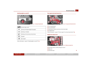 14
14 15
15 16
16 17
17 18
18 19
19 20
20 21
21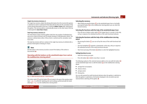 22
22 23
23 24
24 25
25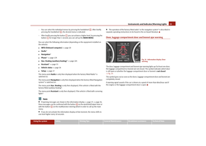 26
26 27
27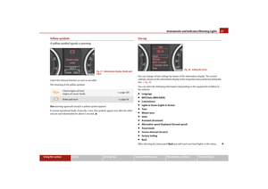 28
28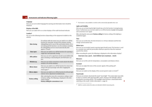 29
29 30
30 31
31 32
32 33
33 34
34 35
35 36
36 37
37 38
38 39
39 40
40 41
41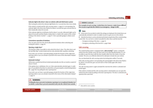 42
42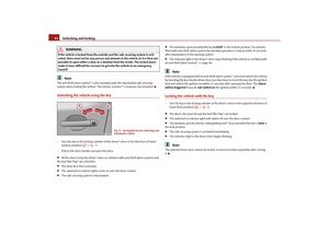 43
43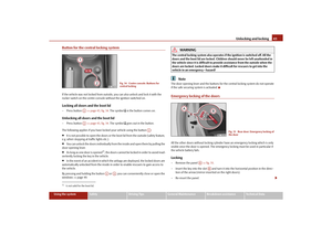 44
44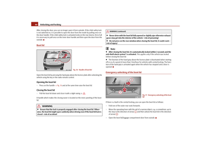 45
45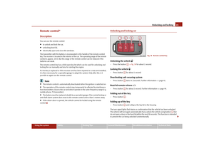 46
46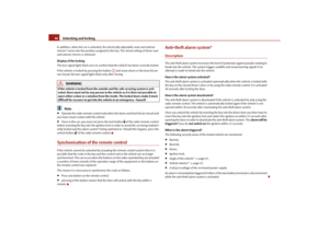 47
47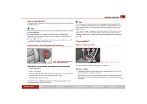 48
48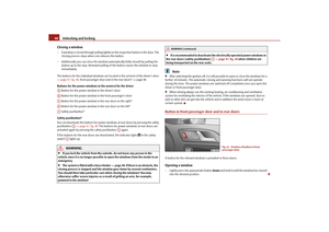 49
49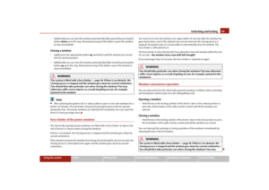 50
50 51
51 52
52 53
53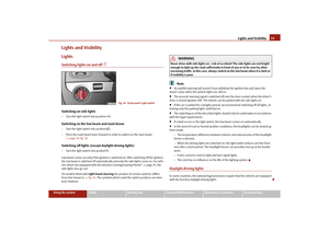 54
54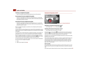 55
55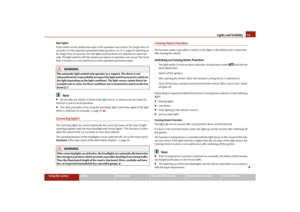 56
56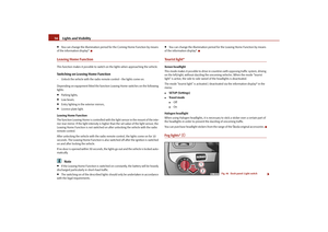 57
57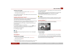 58
58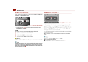 59
59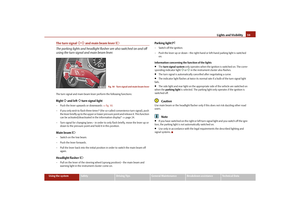 60
60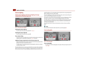 61
61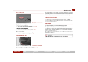 62
62 63
63 64
64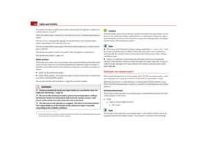 65
65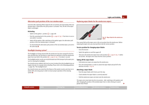 66
66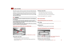 67
67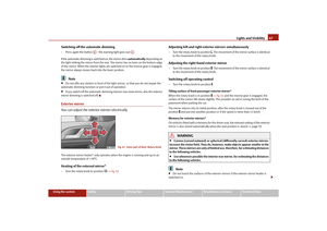 68
68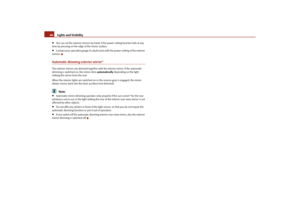 69
69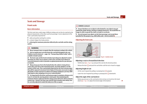 70
70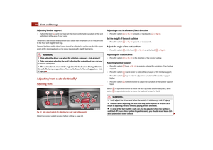 71
71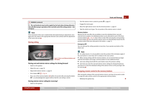 72
72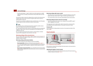 73
73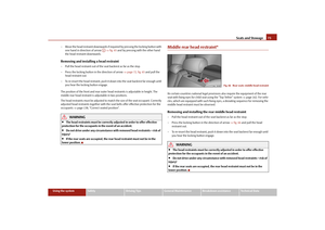 74
74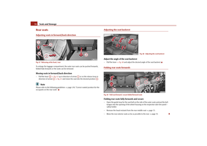 75
75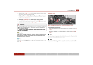 76
76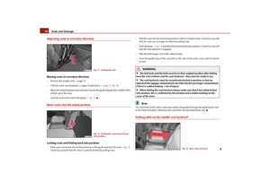 77
77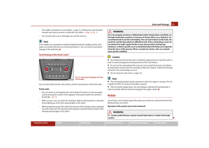 78
78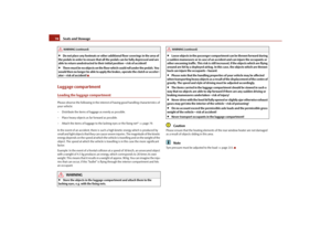 79
79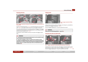 80
80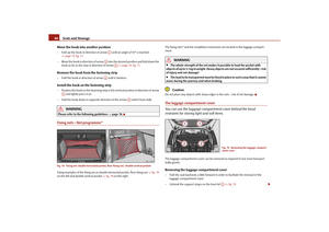 81
81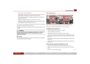 82
82 83
83 84
84 85
85 86
86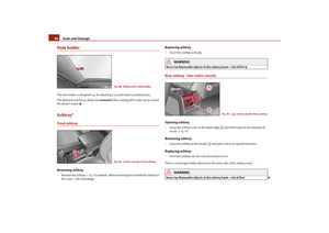 87
87 88
88 89
89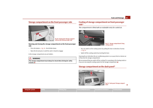 90
90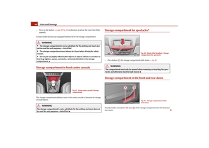 91
91 92
92 93
93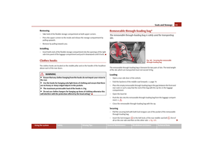 94
94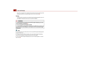 95
95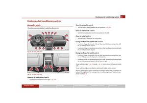 96
96 97
97 98
98 99
99 100
100 101
101 102
102 103
103 104
104 105
105 106
106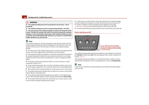 107
107 108
108 109
109 110
110 111
111 112
112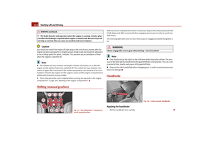 113
113 114
114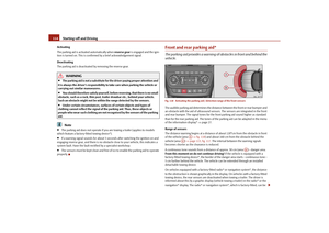 115
115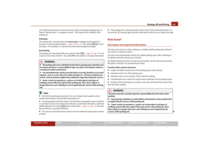 116
116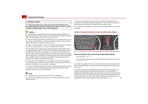 117
117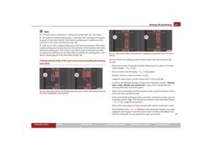 118
118 119
119 120
120 121
121 122
122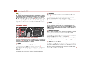 123
123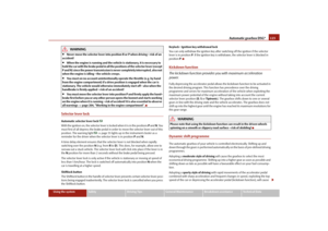 124
124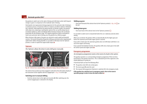 125
125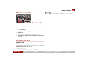 126
126 127
127 128
128 129
129 130
130 131
131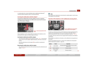 132
132 133
133 134
134 135
135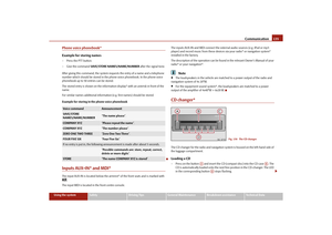 136
136 137
137 138
138 139
139 140
140 141
141 142
142 143
143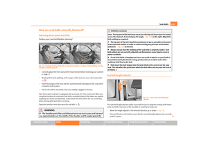 144
144 145
145 146
146 147
147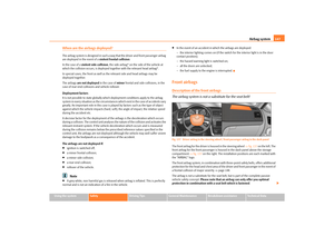 148
148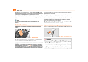 149
149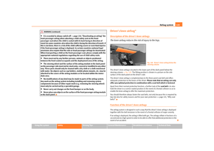 150
150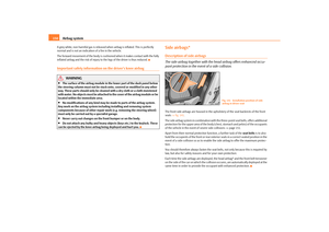 151
151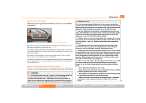 152
152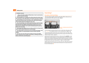 153
153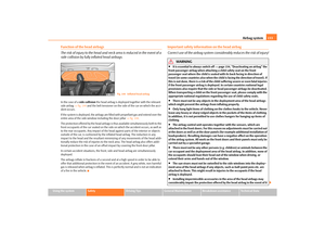 154
154 155
155 156
156 157
157 158
158 159
159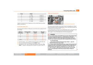 160
160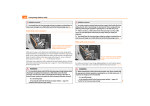 161
161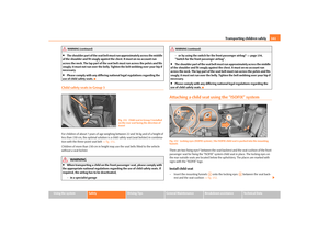 162
162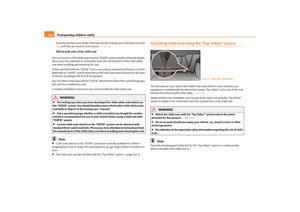 163
163 164
164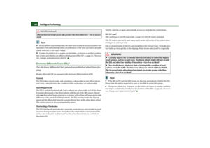 165
165 166
166 167
167 168
168 169
169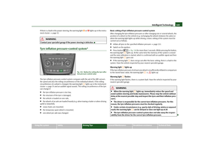 170
170 171
171 172
172 173
173 174
174 175
175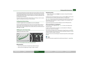 176
176 177
177 178
178 179
179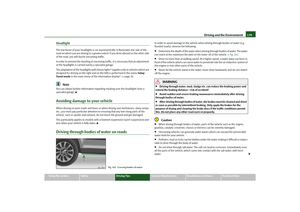 180
180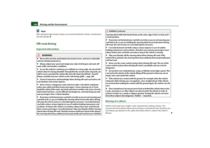 181
181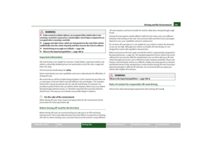 182
182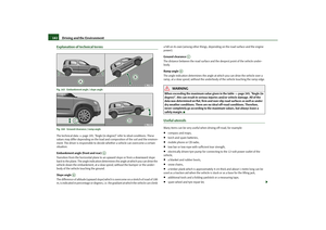 183
183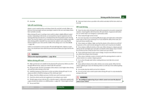 184
184 185
185 186
186 187
187 188
188 189
189 190
190 191
191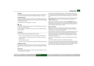 192
192 193
193 194
194 195
195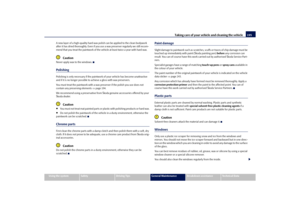 196
196 197
197 198
198 199
199 200
200 201
201 202
202 203
203 204
204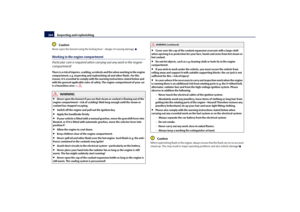 205
205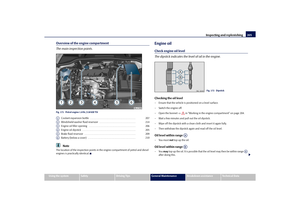 206
206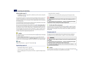 207
207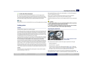 208
208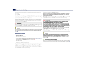 209
209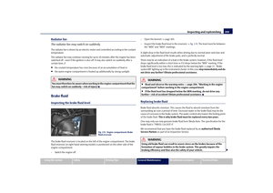 210
210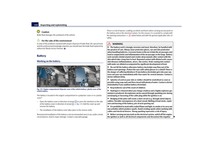 211
211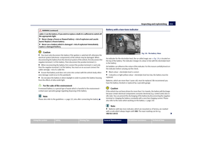 212
212 213
213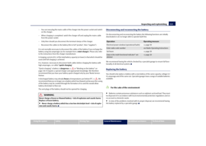 214
214 215
215 216
216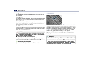 217
217 218
218 219
219 220
220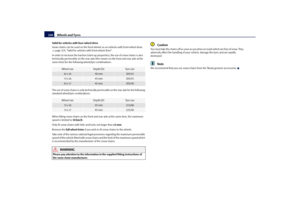 221
221 222
222 223
223 224
224 225
225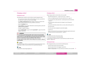 226
226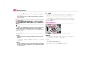 227
227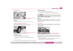 228
228 229
229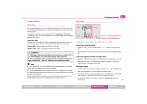 230
230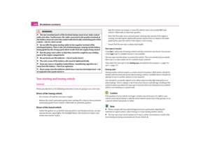 231
231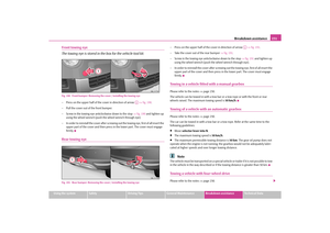 232
232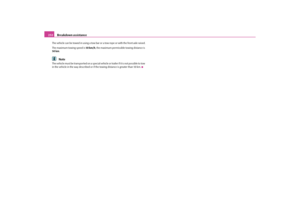 233
233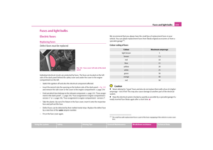 234
234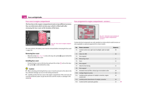 235
235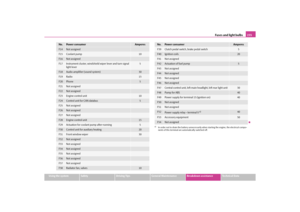 236
236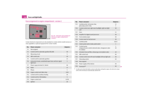 237
237 238
238 239
239 240
240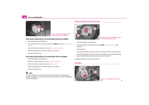 241
241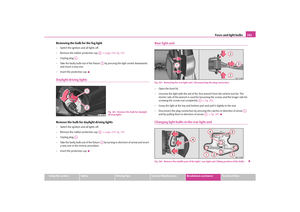 242
242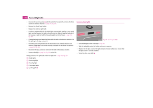 243
243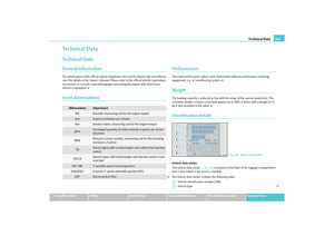 244
244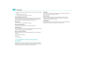 245
245 246
246 247
247 248
248 249
249 250
250 251
251 252
252 253
253 254
254 255
255 256
256 257
257 258
258 259
259 260
260 261
261 262
262 263
263 264
264 265
265 266
266 267
267 268
268 269
269 270
270