Page 17 of 99

62B-17
MR-413-X44-62B000$230_eng.mif
V1
62B
CLIMATE CONTROL
Fault finding - Function
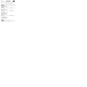
GENERAL INFORMATION:
The climate control function which is fitted to the new Twingo depends on the three computers: injection, UCH and
climate control (DISTRIBUTED FUNCTION).
Fault finding on the air conditioning is performed in two different ways using the diagnostic tool.
The first procedure consists of performing fault finding on each computer which allows dialogue to be established
with just one computer (select the climate control computer).
The second procedure consists of performing fault finding on each function which allows communication with all
three computers belonging to the CLIMATE CONTROL function.
DESCRIPTION OF THE OPERATION OF THE CLIMATE CONTROL COMPUTER:
The climate control computer controls the passenger compartment ventilation, the distribution motor, the mixing
motor and the recirculation motor.
The climate control computer also controls the interior temperature sensor.
The sensor and the three motors are connected to the climate control computer by wire connections. The climate
control computer controls the passenger compartment ventilation using a modulated control signal (square pulse
signal) sent to a power module (MVPE) by a wire connection.
All other signals used by the climate control computer or transmitted by this computer to other computers are sent on
the multiplex network.
The production of cold air (cold loop) and hot air (heating) is controlled by the other two computers involved in the
CLIMATE CONTROL function (UCH and engine injection computer).
Special notes on operation:
–When the engine is stopped, the passenger compartment fan rotates more slowly than when the engine is
running.
–If any of the actuators are faulty, the air conditioning can no longer control them, but the setting requests are still
displayed on the control panel: warning lights light up, display of symbols on the control panel (distribution motor
position, passenger compartment blower speed, AC symbol, etc.).
Vdiag No.: 44
MR-413-X44-62B000$230_eng.mif
Page 18 of 99
62B-18
MR-413-X44-62B000$230_eng.mif
V1
Vdiag No.: 44CLIMATE CONTROL
Fault finding - Function62B
Vehicle
multiplex
network
Internal
temperature
sensor
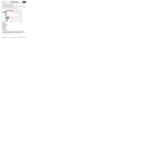
SUMMARY OF ELEMENTS CONTROLLED OR MANAGED BY THE CLIMATE CONTROL COMPUTER:
Ventilation and air conditioning unit
Passenger
comp. blower
Passenger
compartment
blower
power
module
Recirculation
motorDistribution
motorAir mixing
motor
Actuator control Sensor management
Climate control computer (control panel)
Climate
control
management
(hot/cold)Button lightingUser requests
management
(button presses)
Key:
Wire connections =
Multiplex connections =
Page 19 of 99
62B-19
MR-413-X44-62B000$230_eng.mif
V1
Vdiag No.: 44CLIMATE CONTROL
Fault finding - Function62B
Vehicle
multiplex
network
Summary diagram of components controlled or managed by the UCH:
Summary diagram of components controlled or managed by the injection computer Rear screen de-icing and
rear-view mirror de-icer
(depending on version)External
temperature sensor
(depending on
version)
Actuator control Sensor management
UCH
Air conditioning request
managementHeated rear screen control
management
Relay No. 1 for
the Passenger
Compartment
Heating
ResistorsRelay No. 2 for
the Passenger
Compartment
Heating
ResistorsAir conditioning
compressorEngine cooling
fan assemblyEngine
coolant
temperature
sensorRefrigerant
fluid
pressure
sensor
Actuator control Sensor management
Engine injection computer
Management of the cold loop (refrigerant pressure,
engine cooling fan activation request,
compressor activation authorisation, etc.)
Key:
Wire connections =
Multiplex connections =
Page 20 of 99
62B-20
MR-413-X44-62B000$230_eng.mif
V1
Vdiag No.: 44CLIMATE CONTROL
Fault finding - Function62B
ET004: AIR
CONDITIONING
AUTHORISED
Special notes:
This flowchart shows the tracks of
the compressor engagement
request. Components which may
block this request are not listed
(passenger compartment blower
operation signal for the UCH on
manual version with AC, correct
refrigerant pressure for the
injection, etc.).
If the compressor does not engage
(one of the requests is not
transmitted): carry out a conformity
check.
Compressor control flowchart:
ET140: AIR
CONDITIONING
REQUEST
(climate control)Air conditioning control
panel
ET020: COMPRESSOR
CONTROL
(climate control)
ET030: AIR
CONDITIONING
REQUEST 2UCH
ET088: COMPRESSOR
ACTIVATION
REQUEST
Injection computer
Air conditioning
Compressor
Key:
: Multiplex signals
: Wire connections
Page 21 of 99

62B-21
MR-413-X44-62B000$276_eng.mif
V1
62B
CLIMATE CONTROL
Fault finding - Replacement of components
REPLACING THE CLIMATE CONTROL COMPUTER
–Note the computer configuration according to the optional equipment fitted on the vehicle (see climate control
computer configuration) or using the Shared World Information (ICM).
–Ensure that the ignition is switched off.
–After approval from the Techline, replace the computer.
–Switch on the ignition and carry out a check using the diagnostic tool.
–Configure the computer according to the vehicle specifications.
–Switch off the ignition and then back on for the configurations to register.
–Check in the Read configuration menu that the configurations have been recognised correctly.
–Check for faults and apply the corresponding fault finding procedure for any faults shown on the diagnostic tool.
–Clear any stored faults.
–Run command VP001 Enter VIN.
–Start the engine, switch on the air conditioning and ensure that it is operating correctly. WARNING
Before replacing the climate control computer, check that it is faulty (read faults, conformity of variables,
read customer complaints). Replacement of the computer must be authorised by the Techline after a fault
finding log has been completed and submitted.
Vdiag No.: 44
MR-413-X44-62B000$276_eng.mif
Page 22 of 99

62B-22
MR-413-X44-62B000$322_eng.mif
V1
62B
CLIMATE CONTROL
Fault finding - Configuration and programming
CLIMATE CONTROL COMPUTER CONFIGURATION
The climate control computer has three configuration functions. These configurations need to be set after replacing
the computer.
These three configurations are important as they ensure that climate control is optimised within the vehicle (better
control compared to automatic air conditioning). If these configurations are not entered correctly, cold air and warm
air production will be severely affected.
These configurations can be accessed in repair mode by the diagnostic tool and can only be entered using
the fault finding by computer menu as opposed to the fault finding by function menu.
These configurations can also be read using the diagnostic tool in repair mode to ensure they have been correctly
set. Configurations can be read in fault finding by computer mode and fault finding by function mode.
Configuration Option Configuration reading
CF044Vehicle type – New TwingoLC013Vehicle type
CF024Geographical zone– Zone 1
– Zone 2LC046Geographical zone
CF117Type of heating
resistors – None
– 900 WLC044Type of heating
resistors
WARNING
–The "ZONE 1" configuration must be selected for HOT AND HUMID COUNTRIES which correspond to the
technical and legislative criteria available on the Shared World Information.
–The "ZONE 2" configuration must be selected for TEMPERATE COUNTRIES which correspond to the
technical and legislative criteria available on the Shared World Information.
Note:
In hot and humid climates, when the heating and air conditioning system is in operation, condensation
may form on the outside of the windscreen.
The "ZONE 1" configuration corrects this customer complaint.
Note:
In fault finding by function mode, the diagnostic tool can also display the configuration readings of the other
computers involved in the air conditioning function. All of the air conditioning function configurations (of the
injection computer and UCH computer) are listed (See 62C, Air conditioning).
Vdiag No.: 44
MR-413-X44-62B000$322_eng.mif
Page 23 of 99
62B-23
MR-413-X44-62B000$322_eng.mif
V1
CLIMATE CONTROL
Fault finding - Configuration and programming
Vdiag No.: 44
62B
MIXING AND DISTRIBUTION MOTOR PROGRAMMING PROCEDURE:
There is no specific programming operation for the air mixing motor or the distribution motor.
However, the minimum and maximum limits of these motors have to be programmed. This operation is automatic
and is performed in the following cases:
–after communication using the diagnostic tool, the next time ignition is switched on,
–if a fault, declared as present when the ignition was switched off, disappears the next time the ignition is switched
on.
WARNING
It is imperative that communication is established with the diagnostic tool (to initiate programming the
next time the ignition is switched on) after any operation on the distribution and mixing motors or on the
control panel.
Page 24 of 99
62B-24
MR-413-X44-62B000$368_eng.mif
V1
62B
CLIMATE CONTROL
Fault finding - Fault summary table
SUMMARY OF SENSORS AND ACTUATORS ON WHICH FAULT FINDING CAN BE PERFORMED BY THE
CLIMATE CONTROL COMPUTER (with corresponding design office codes)
Tool faultAssociated
DTCDiagnostic tool title
DF0019105 Computer
DF0079101 Interior temperature sensor circuit
DF0109107 Mixing motor circuit
DF0129108 Distribution motor circuit
DF0219106 Air recirculation motor circuit
Vdiag No.: 44
MR-413-X44-62B000$368_eng.mif