Page 9 of 99

62B-9
MR-413-X44-62B000$092_eng.mif
V1
CLIMATE CONTROL
Fault finding - List and location of components
Vdiag No.: 44
62B
●HEATING COMPONENTS
–Heater matrix: This is located at the bottom of the heating and air conditioning unit.
–Passenger compartment heating resistors: These are located at the bottom of the heater matrix on the
driver's side (depending on the equipment).
●SENSOR
–Interior temperature sensor: This is located on the interior rear-view mirror.
●ACTUATORS
–Air distribution flap: This is located in the heating and air conditioning unit.
–Air mixing flap: This is located in the heating and air conditioning unit.
–Recirculation flap: This is located behind the dashboard.
–Flap motors: These are located close to the flaps.
●OTHERS
–Passenger compartment blower unit: This is located in the heating and air conditioning unit.
–Cooling fan assembly: This is located in the front panel of the vehicle, in front of the condenser.
–Climate control computer: This is located in the control panel.
–Air pipes: Theses are located under the dashboard.
Page 10 of 99
62B-10
MR-413-X44-62B000$138_eng.mif
V1
62B
CLIMATE CONTROL
Fault finding - Role of components
●COLD LOOP COMPONENTS
System assembly
1Heating and air conditioning unit
2Heater matrix
3Expansion valve and evaporator
4Coolant circuit
5Cold loop
6Condenser and radiator
7Compressor
–Compressor:
The compressor is not activated when the exterior temperature is less than 0˚; it is used to compress the refrigerant
fluid into gas. The pressure can reach up to 28 bar.
Air conditioning compressor
Vdiag No.: 44
MR-413-X44-62B000$138_eng.mif
Page 11 of 99

62B-11
MR-413-X44-62B000$138_eng.mif
V1
CLIMATE CONTROL
Fault finding - Role of components
Vdiag No.: 44
62B
–Condenser:
The condenser is composed of flat horizontal aluminium tubes. The pipes are divided by the vanes in order to increase
the air heat exchange and therefore cool the refrigerant fluid to produce condensation.
Condenser + Dehydrator reservoir
1Condenser
2Dehydration canister
–Dehydrator reservoir: (see figure above)
The dehydrator reservoir is used to:
●Check the condition of the refrigerant.
●Absorb the variations in volume (expansion bottle principle).
●Filter impurities.
●Absorb moisture (water in the circuit).
–Heating and air conditioning unit: (see figure above)
This unit acts as an air mixing box. It is equipped with a system of flaps which allow the air to be directed in accordance
with the requirements of the occupants whilst simultaneously allowing the temperature of the air entering the
passenger compartment to be modified by mixing hot and cold air.
–Thermostatic expansion valve: (see figure below)
This thermostatic-type expansion valve is used to check refrigerant expansion. It is located at the evaporator inlet.
–Evaporator: (see figure below)
●The evaporator is a heat exchanger which enables the air entering the passenger compartment to be cooled.
Note: Condensation of the air may occur thereby causing normal drops of water to form under the body.
Evaporator + expansion valve
1Expansion valve
2Evaporator
Page 12 of 99

●The High Pressure")
62B-12
MR-413-X44-62B000$138_eng.mif
V1
CLIMATE CONTROL
Fault finding - Role of components
Vdiag No.: 44
62B
–High and low pressure pipes: (see figure below)
●The High Pressure and Low Pressure pipes are composed of rigid aluminium pipes and flexible pipes that
enable engine-related movements to be absorbed.
●Two filler valves (High Pressure and Low Pressure) can be accessed in order to fill (or drain) the refrigerant loop.
●The connections must be checked in the event of a refrigerant fluid leak.
Cold loop pipes
1Buffering capacity
2Expansion valve outlet
3Expansion valve inlet
4High pressure filler valve
5Low pressure filler valve
6Condenser inlet
7Condenser outlet
8Pressure sensor
9Compressor inlet
10 Compressor outlet
●HEATING COMPONENTS
–Heater matrix:
The external air entering the heating and air conditioning device (HVAC) is heated by the heater matrix.
–Passenger Compartment Heating Resistors (depending on the equipment): (see figure below)
The passenger compartment heating resistors (RCH) are electrical heating devices in the air conditioning unit. This
system is an additional heating system which operates when the engine is cold (when starting).
Page 13 of 99

●SENSOR
–Interior temp")
62B-13
MR-413-X44-62B000$138_eng.mif
V1
CLIMATE CONTROL
Fault finding - Role of components
Vdiag No.: 44
62B
Passenger Compartment Heating Resistors (RCH)
●SENSOR
–Interior temperature sensor:
This sensor is used to measure the air temperature of the passenger compartment.
●ACTUATORS
–Air distribution flap:
This flap enables the air flowing into the passenger compartment to be directed.
–Air mixing flap:
This flap enables the temperature requirements of the occupants to be met.
–Recirculation flap:
This flap prevents the entry of exterior air. In this case, the passenger compartment is isolated from the exterior and
air is blown in the passenger compartment in a closed circuit.
–Flap motors: these motors enable the flaps to be moved electrically. There are 3 motors: One motor for the air
mixing flap (stepper-motor), one motor for the distribution flap (stepper-motor) and one motor for the
recirculation flap (direct current motor).
●OTHERS
–Passenger compartment blower unit:
The passenger compartment blower unit is controlled by the Electronic Blower Dimmer Module (MVPE).
Electronic Blower Dimmer Module (MVPE)
Page 14 of 99
62B-14
MR-413-X44-62B000$138_eng.mif
V1
CLIMATE CONTROL
Fault finding - Role of components
Vdiag No.: 44
62B
The passenger compartment blower unit is used to vary the rate at which air is blown into the passenger
compartment, depending on the requirements of the customer.
–Cooling fan assembly:
The cooling fan assembly motor is normally used in order to promote heat exchange in the condenser and therefore
improve the performance of the air conditioning system. Activation of the air conditioning fan unit depends, among
other things, on the vehicle speed and high pressure in the loop.
–Climate control computer:
The climate control computer is in permanent communication with the UCH and injection computers. It controls a
number of parameters:
●Meteorological (temperature, etc.)
●Vehicle (speed, engine speed, circuit temperature and pressure)
●Comfort (interior temperature).
Climate control panel: front panel
Climate control panel: rear panel
Page 15 of 99
62B-15
MR-413-X44-62B000$138_eng.mif
V1
CLIMATE CONTROL
Fault finding - Role of components
Vdiag No.: 44
62B
–Air pipes:
The air flows into an open air inlet scoop towards the exterior. Therefore there must be enough air flow for it to be
channelled into the passenger compartment. This flow can be created by the vehicle speed (in non-recirculation
mode) or by activating the blower. The air flowing into the passenger compartment is protected by a grille and a rain
shield in order to prevent foreign bodies and water from entering. The air is then distributed inside the passenger
compartment.
Passenger compartment air pipes
1Air inlet
2De-icing
3Right-hand air vent
4Left-hand air vent
5Centre air vents
6Left-hand footwell vent
7Right-hand footwell vent
Page 16 of 99
62B-16
MR-413-X44-62B000$184_eng.mif
V1
62B
CLIMATE CONTROL
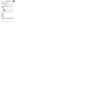
Fault finding - Operating diagram
Summary diagram of all the components of the air conditioning system
1Evaporator
2Temperature sensor
3Compressor
4Condenser
5Fan assembly
6Pressure switch
7Dehydration canister
8Expansion valve
Vdiag No.: 44
MR-413-X44-62B000$184_eng.mif