Page 89 of 99

62B-89
MR-413-X44-62B000$920_eng.mif
V1
62B
CLIMATE CONTROL
Diagnostic - Fault finding chart
ALP 10 Inefficient rear screen de-icing/demisting
NOTESCarry out this conformity check after a full check using the diagnostic tool
(fault reading, especially UCH and injection faults and configuration checks).
Check that the fuses are sound.
Use a multimeter and a 21 W test light.
Use the Wiring Diagram Technical Note, NEW TWINGO.
Special notes:
Check that the inside of the windows are not greasy as this reduces the efficiency of
the de-icing.
Note:
The de-icing control is only authorised when the engine is running to save power.
The rear screen de-icer control is activated by pressing the de-icing button at the
bottom of the climate control panel in manual mode (with time delay and rear-view
mirror de-icer).
Ensure that there are no water leaks in the passenger compartment which would significantly increase the
moisture and reduce the effectiveness of the demisting function (see ALP 12 if the fault is noted).
Is the fault still present?
YES NO
Check that the UCH is correctly configured by viewing the configuration reading LC013 Type of air conditioning.
Reconfigure the UCH if necessary.
Check that the UCH receives the signal about the
status and operation of the engine. In the Cold Loop
screen, status ET142 "engine operating phase"
should display RUNNING.
Is status ET142 RUNNING?
YES
End of fault finding procedure.
NOCarry out fault finding on the UCH
(interpretation of status ET142) and on the
multiplex network.
AFTER REPAIRCarry out a complete check with the diagnostic tool.
Vdiag No.: 44
MR-413-X44-62B000$920_eng.mif
Page 90 of 99

62B-90
MR-413-X44-62B000$920_eng.mif
V1
Vdiag No.: 44CLIMATE CONTROL
Diagnostic - Fault finding chart62B
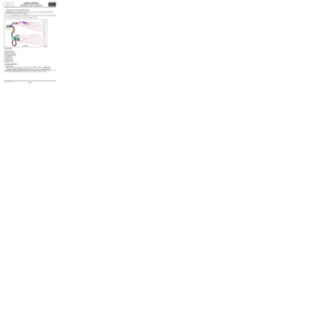
ALP 10
CONTINUED
Press the de-icing button on the control panel and
check status:
–ET086 heated rear screen for climate control.
Is status ET086 “ACTIVE”?
YES
Connect a test light between connections 15LP and
MYH of component 200 and, using the diagnostic
tool, run command AC060 Rear screen de-icer
(UCH command mode menu).
Does the test light illuminate?
YES
Connect a test light between connection 15LP and
the chassis earth and use the diagnostic tool to
run command AC060 Rear screen de-icer
(UCH command mode menu).
Does the test light illuminate?
NO
Check the continuity of connection 15LP between
components 200 and 645.
Is the continuity correct?
YES
See 87B, UCH, Interpretation of commands, for command AC060 Rear screen de-icer.
NORear de-icing request interpretation fault
on the climate control computer. Carry out
fault finding on the climate control
computer (see Interpretation of
statuses).
NOCheck the resistance of the rear screen
de-icer lines. The line resistance must not
be zero or infinite. If the resistance is not
correct, replace the rear screen (see MR
412, Bodywork, 54A, Windows, Rear
screen window: Removal - Refitting).
YESContinuity fault on connection MYH of
component 200. If there is a repair method
(see Technical Note 6015A, Repairing
electrical wiring, Wiring: Precautions
for repair), repair the wiring, otherwise
replace the wiring.
NOContinuity fault on connection 15LP
between components 200 and 645.
If there is a repair method (see Technical
Note 6015A, Repairing electrical wiring,
Wiring: Precautions for repair), repair
the wiring, if not replace the wiring.
AFTER REPAIRCarry out a complete check with the diagnostic tool.
Page 91 of 99

62B-91
MR-413-X44-62B000$920_eng.mif
V1
Vdiag No.: 44CLIMATE CONTROL
Diagnostic - Fault finding chart62B
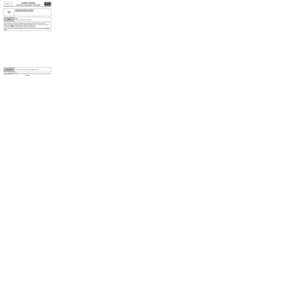
ALP 11 Unpleasant odours in the passenger compartment
NOTESOnly consult this customer complaint after a complete check with the diagnostic
tool.
Check that the cabin filter is not blocked or damaged
(see MR 411 Mechanical, 61A, Heating, Cabin filter:
Removal - refitting).
Replace it if necessary.
Is the fault still present?
YES
Check that the condensate (water from the evaporator)
drain ring is not obstructed (beneath the body).
Repair if necessary.
Is the fault still present?
YES
Check the sealing of the heating unit in relation to the
engine compartment:
- Foam seal on the heater matrix coolant pipes fitted and
in good condition.
- Rubber seal on the radiator tank fitted and in good
condition (seal under the bonnet separating the engine
compartment from the windscreen aperture).
- Drain valve on the radiator tank fitted and in good
condition.
Repair if necessary.
Is the fault still present?
YES
Remove the passenger compartment filter to apply air
conditioning system cleaner using an extension piece on
the evaporator. Spray the entire contents of the aerosol.
Leave the product to work for 15 minutes.
NOEnd of fault finding procedure.
NOEnd of fault finding procedure.
NOEnd of fault finding procedure.
AFTER REPAIRCarry out a complete check with the diagnostic tool.
CLIM_V44_ALP11
Page 92 of 99

62B-92
MR-413-X44-62B000$920_eng.mif
V1
Vdiag No.: 44CLIMATE CONTROL
Diagnostic - Fault finding chart62B
ALP 12 Water is present in the passenger compartment
NOTESOnly consult this customer complaint after a complete check with the diagnostic
tool.
Pressurise the cooling circuit.
Is there any coolant leaking into the vehicle?
NO
Check that the evaporator evacuation ring is not
blocked (under the body).
Repair if necessary.
Is the fault still present?
YES
Make sure that the scuttle panel (under the windscreen aperture) is not filled with water. If it is, check that the
drain valve is fitted to the scuttle panel and is in good condition.
Replace the valve if necessary.
Has the customer just washed the vehicle?
YES
Explain to the customer that when washing the car
using a hose pipe, the water jet must not be left for
too long on the air inlet in the scuttle panel (on the
bonnet).
YES Repair.
NOEnd of fault finding procedure.
NO End of fault finding procedure.
AFTER REPAIRCarry out a complete check with the diagnostic tool.
CLIM_V44_ALP12
Page 93 of 99

62B-93
MR-413-X44-62B000$920_eng.mif
V1
Vdiag No.: 44CLIMATE CONTROL
Diagnostic - Fault finding chart62B
ALP 13 Lighting fault on the control panel in night mode
NOTESOnly consult this customer complaint after a complete check of the multiplex
network and the air conditioning with the diagnostic tool.
Special notes:
With the ignition on, the control panel screen is permanently on but the panel buttons
only light up when the side lights are switched on.
Note:
If the exterior temperature sensor is faulty, the climate control computer is
activated 5 seconds after the ignition is switched on (the UCH performs fault
finding on the exterior temperature sensor).
Use the Wiring Diagram Technical Note for the New Twingo.
Is the fault shared with other components (first row cigarette lighter, radio, multifunction display, cruise control/
speed limiter on off switch, etc.)
YES NO
Switch on the ignition and the side lights.
Using the diagnostic tool and the conformity
check, check that the lighting dimmer is operating
correctly using parameter PR122 NIGHT TIME
LIGHTING LEVEL.
Does the parameter vary?
YES
Check the connection and condition of the
connector of component 419.
If there is a repair method (see Technical Note
6015A, Electrical wiring repair, Wiring: Repair
precautions), repair the wiring, otherwise replace it.
If the fault is still present, contact the Techline.
NOCarry out a fault finding procedure of the
instrument panel.
Run a multiplex network test (see 88B,
Multiplex).
AFTER REPAIRCarry out a complete check with the diagnostic tool.
CLIM_V44_ALP13
Page 94 of 99

62B-94
MR-413-X44-62B000$920_eng.mif
V1
Vdiag No.: 44CLIMATE CONTROL
Diagnostic - Fault finding chart62B
ALP 13
CONTINUED
Switch off the ignition and turn off the side lights.
Disconnect the connectors of components 101, 1081, 1222, 1391, 319, 184, 1390, 261, 653, 1016 and 419 of
connection LPD (see Wiring Diagrams Technical Note, Twingo 2 passenger compartment fuse board,
component code 1016, connection code LPD).
Check the insulation, continuity and the absence of interference resistance of connection LPD between
components 419 and 1016.
If the connection is faulty (see Technical Note 6015A, Repairing electrical wiring, Wiring: Precautions for the
repair), repair the wiring, otherwise replace the wiring.
YES
If the check does not reveal any electrical faults, check the conformity of the components on connection LPD
(component in short circuit, etc.)
Check the condition and position of fuse F42 (10 A) in the passenger compartment fuse box.
Consult section 81C Fuses.
Repair if necessary.
Is the fault still present?
YES
Contact the Techline.
NOEnd of fault finding procedure.
AFTER REPAIRCarry out a complete check with the diagnostic tool.
Page 95 of 99

62B-95
MR-413-X44-62B000$920_eng.mif
V1
CLIMATE CONTROL
Diagnostic - Fault finding chart
Vdiag No.: 44
62B
ALP 14 Noisy compressor
NOTESOnly deal with this customer complaint after a full check with the diagnostic tool
(fault reading and configuration checks).
WARNING
Check that the computers active in the AIR CONDITIONING function (Injection, UCH
and climate control) are correctly configured.
Note:
Before starting any work, check that the noise is indeed coming from the compressor.
Check that the compressor belt is in good condition and check its tension (for engines without automatic
tensioning) (see MR 411, Mechanical, 11A, Top and front of engine, Accessories belt: Removal - Refitting).
Check that the compressor is correctly fixed (see MR 411 Heating and air conditioning system, 62A,
Air conditioning, Compressor: Removal - Refitting).
Check the refrigerant fluid and look for any leaks. Significant loss of fluid causes the compressor to make noises.
(see Technical Note 6001A, Air conditioning, 62A, Air conditioning, Air conditioning: Check).
If the fault is still present, replace the air conditioning compressor (see MR 411, Mechanical, 62A,
Air conditioning, Compressor: Removal - Refitting).
AFTER REPAIRCarry out a complete check with the diagnostic tool.
Page 96 of 99

62B-96
MR-413-X44-62B000$966_eng.mif
V1
62B
CLIMATE CONTROL
Fault finding - Help
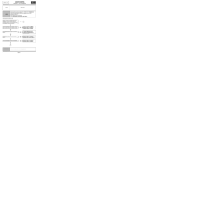
MEASURING THE CONTROL VOLTAGE OF THE PASSENGER COMPARTMENT FAN UNIT POWER MODULE
There are two ways to measure the control voltage of the passenger compartment blower power module:
1 / MEASURING USING A MULTIMETER (in the voltmeter position, direct current measurement):
This voltage measurement only gives an indication (average of non-representative voltages) and is not a rigourous
method. However, this method can be used if no oscilloscope is available or simply as a guide value.
With the power module connector disconnected, measure between connection 38LR of component 1023 and the
earth MAN.
At speed 0 the voltage measured is equal to the battery voltage (± 1 V) and at speed 8 the voltage is 0 V (± 0.5 V).
For the seven intermediate speeds, the voltage varies between 0 and the battery voltage.
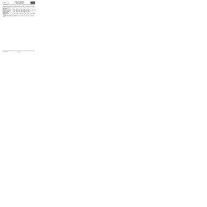
Examples of measurements taken with the voltmeter with the engine at idle speed (values given as a guide):
Note:
These values are given for a battery voltage of + 12 V.
2 / MEASURING USING AN OSCILLOSCOPE (Optima 5800, CLIP technique):
The fan assembly power module is controlled by pulse width modulated control voltage (PWM*). This control voltage
is always 12 V, it is the control signal (square signal) that varies:
The amplitude and frequency do not vary but instead the high status (12 V) varies in relation to the low status (0 V).
To make this measurement, connect the oscilloscope earth lead to the battery earth and the oscilloscope measuring
lead to connection 38LR of component 1023 (power module connector connected).
Adjust the oscilloscope's time base to 500 µs per division with a range of 5 V per division and set the oscilloscope to
the Auto position by selecting the Trigger mode.
The signals obtained must be:
–a straight line at 12 V (±1) for speed 0,
–a straight line at 0 V (± 0.5 V) for speed 8. Passenger compartment
blower speed01 23 45 67 8
Voltage measurement
in V at the PWM* terminals11.73 V 9.5 V 9 V 8.3 V 7.2 V 6.6 V 5.4 V 3.6 V 0.4 V
Voltage measurement
in V at the fan assembly
terminals02.53.24.3 5.6 6.6 8 10 12
PR019 Passenger
compartment blower
PWM* setting0 % 20 % 25 % 33 % 43 % 50 % 60 % 77 % 100 %
Vdiag No.: 44
MR-413-X44-62B000$966_eng.mif