Page 138 of 273

DIESEL INJECTION
Fault finding – Conformity check13B
13B - 138V3 MR-372-J84-13B250$450.mif
EDC16
PROGRAM NO.: C1
Vdiag No.: 51
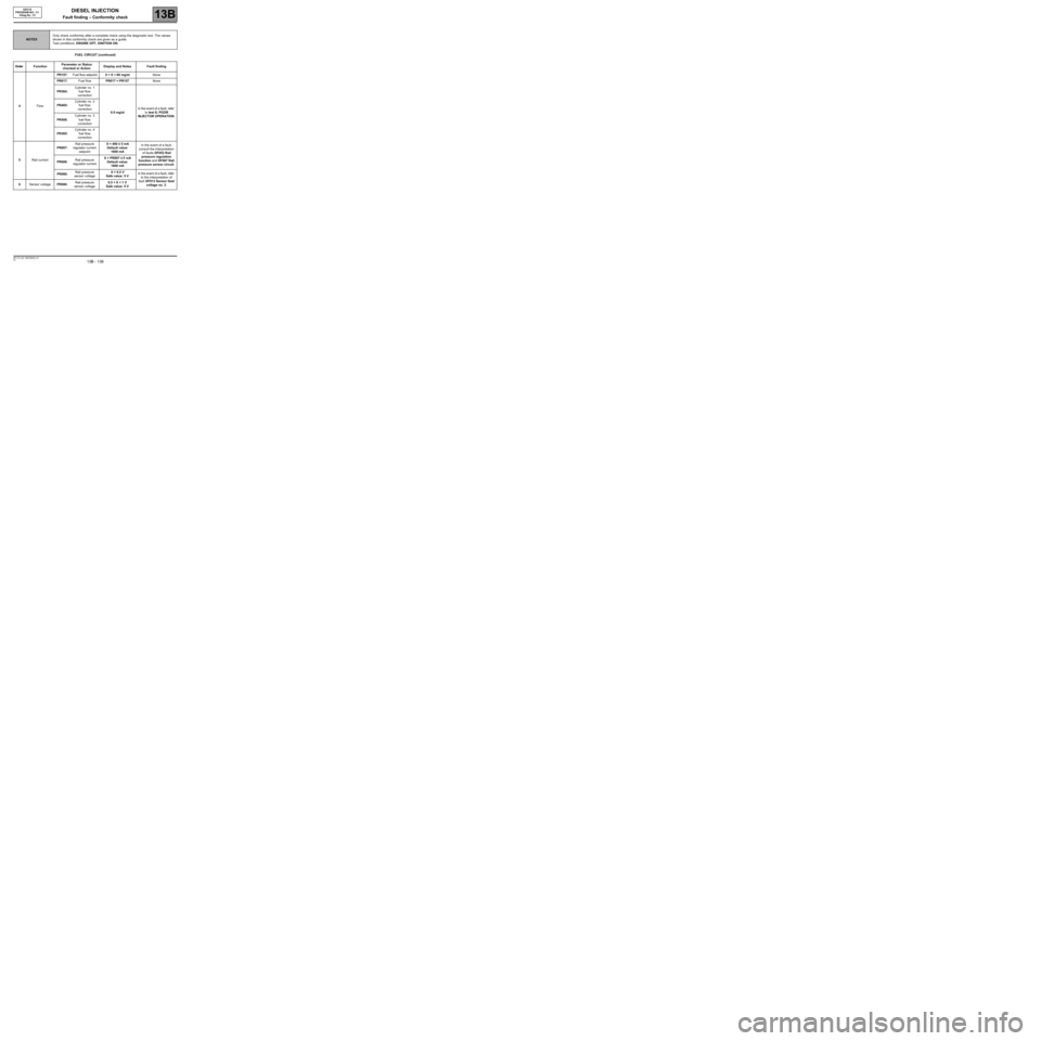
FUEL CIRCUIT (continued)
NOTESOnly check conformity after a complete check using the diagnostic tool. The values
shown in this conformity check are given as a guide.
Test conditions: ENGINE OFF, IGNITION ON.
Order FunctionParameter or Status
checked or ActionDisplay and Notes Fault finding
4FlowPR157:Fuel flow setpoint0 < X < 60 mg/stNone
PR017:Fuel flowPR017 = PR157None
PR364:Cylinder no. 1
fuel flow
correction
0.0 mg/stIn the event of a fault, refer
to test 8: POOR
INJECTOR OPERATION. PR405:Cylinder no. 2
fuel flow
correction
PR406:Cylinder no. 3
fuel flow
correction
PR365:Cylinder no. 4
fuel flow
correction
5Rail currentPR007:Rail pressure
regulator current
setpointX = 400 ± 5 mA
Default value:
1600 mAIn the event of a fault,
consult the interpretation
of faults DF053 Rail
pressure regulation
function and DF007 Rail
pressure sensor circuit. PR006:Rail pressure
regulator currentX = PR007 ± 5 mA
Default value:
1600 mA
PR080:Rail pressure
sensor voltageX = 0.5 V
Safe value: 5 VIn the event of a fault, refer
to the interpretation of
fault DF013 Sensor feed
voltage no. 3. 6Sensor voltagePR080:Rail pressure
sensor voltage0.5 < X < 1 V
Safe value: 5 V
Page 156 of 273

DIESEL INJECTION
Fault finding – Conformity check13B
13B - 156V3 MR-372-J84-13B250$450.mif
EDC16
PROGRAM NO.: C1
Vdiag No.: 51
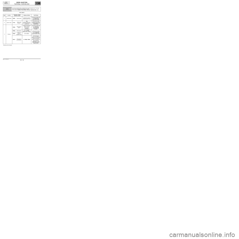
FUEL CIRCUIT
*Opening cyclic ratio signal
NOTESOnly check conformity after a complete check using the diagnostic tool. The values
shown in this conformity check are given as a guide.
Test Conditions: ENGINE AT IDLE SPEED, COOLANT TEMPERATURE > 80 ˚C.
Order FunctionParameter or Status
checked or ActionDisplay and Notes Fault finding
1Engine speedPR055:Engine speedIndicates the engine's
rotational speed in rpm.In the event of a fault, refer
to the interpretation for
fault DF005 Engine
speed sensor circuit.
2Injector codesET104:Injector code
operationYES
Indicates whether the
injector codes have been
programmedIn the event of a fault,
consult the interpretation
of DF276 Injector code
programming.
3PressurePR008:Rail pressure
setpointIndicates the theoretical
pressure value for
optimum engine
operation
X = 270 ± 50 barIn the event of a fault, refer
to the interpretation of
fault DF053 Rail
pressure regulator
function.
PR038:Rail pressureX = ~ 315 bar
Default value: 250 bar.In the event of a fault,
consult the interpretation
of fault DF007 Rail
pressure sensor circuit. PR048:OCR* rail
pressure
regulation valve35 < X <45 %
PR213:Rail pressure
loop differenceX = PR008 - PR038The fuel pressure
variation is the difference
between the rail pressure
and the rail pressure
setpoint. In the event of a
fault, consult the
interpretation of fault
DF007 Rail pressure
sensor circuit.
Page 157 of 273

DIESEL INJECTION
Fault finding – Conformity check13B
13B - 157V3 MR-372-J84-13B250$450.mif
EDC16
PROGRAM NO.: C1
Vdiag No.: 51
FUEL CIRCUIT (continued)
NOTESOnly check conformity after a complete check using the diagnostic tool. The values
shown in this conformity check are given as a guide.
Test Conditions: ENGINE AT IDLE SPEED, COOLANT TEMPERATURE > 80 ˚C.
Order FunctionParameter or Status
checked or ActionDisplay and Notes Fault finding
4FlowPR017:Fuel flowX = 0 < X < 60 mg/stNone
PR157:Fuel flow setpointPR017 = PR157None
PR364:Cylinder no. 1
fuel flow
correction
± 1 mg/stIn the event of a fault, refer
to the interpretation of
test 8: POOR INJECTOR
OPERATION. PR405:Cylinder no. 2
fuel flow
correction
PR406:Cylinder no. 3
fuel flow
correction
PR365:Cylinder no. 4
fuel flow
correction
5Rail currentPR007:Rail pressure
regulator current
setpointX = 1400 ± 50 mA
Default value:
1600 mAIn the event of a fault,
consult the interpretation
of fault DF007 Rail
pressure sensor circuit.
PR006:Rail pressure
regulator currentX = PR007 ± 5 mA
Default value:
1600 mA
PR080:Rail pressure
sensor voltage1 < X < 1.5 V
Safe value: 5 VIn the event of a fault, refer
to the interpretation of
fault DF013 Sensor feed
voltage no. 3
Page 206 of 273

DIESEL INJECTION
Fault finding – Parameter summary table13B
13B - 206V3 MR-372-J84-13B250$675.mif
EDC16
PROGRAM NO.: C1
Vdiag No.: 51DIESEL INJECTION
Fault finding – Parameter summary table
OCR*: opening cyclic ratioTool parameter Diagnostic tool title
PR005EGR valve opening setpoint
PR006Rail pressure regulator current
PR007Rail pressure regulator current setpoint
PR008Rail pressure setpoint
PR009Turbocharging pressure setpoint
PR011Turbocharging solenoid valve position correction
PR015Engine torque
PR016Alternator flow
PR017Fuel flow
PR022EGR valve position feedback loop difference
PR030Accelerator pedal position
PR035Atmospheric pressure
PR037Refrigerant pressure
PR038Rail pressure
PR041Turbocharging pressure
PR047Turbocharging pressure OCR*
PR048OCR* rail pressure regulation valve
PR051EGR valve position feedback
PR053Speed requested by air conditioning
PR055Engine speed
PR059Inlet air temperature
PR061Exterior air temperature
PR064Coolant temperature
PR071Computer feed voltage
PR073Air flowmeter feed voltage
PR076Refrigerant sensor voltage
PR077EGR valve position sensor voltage
MR-372-J84-13B250$675.mif
Page 207 of 273

DIESEL INJECTION
Fault finding – Parameter summary table13B
13B - 207V3 MR-372-J84-13B250$675.mif
EDC16
PROGRAM NO.: C1
Vdiag No.: 51
OCR*: opening cyclic ratioTool parameter Diagnostic tool title
PR079Atmospheric pressure sensor voltage
PR080Rail pressure sensor voltage
PR081Inlet temperature sensor voltage
PR084Coolant temperature sensor voltage
PR089Vehicle speed
PR128First EGR valve offset
PR129Last EGR valve offset
PR130Cruise control setpoint
PR131EGR air flow variation
PR132Air flow
PR146Inlet air flow
PR147Pedal potentiometer voltage gang 1
PR148Pedal potentiometer voltage gang 2
PR157Fuel flow setpoint
PR171Air flow setpoint for EGR
PR190Engine idle speed setpoint.
PR213Rail pressure loop difference
PR220EGR valve OCR*
PR358Sensor reference voltage
PR364Cylinder no. 1 fuel flow correction
PR365Cylinder no. 4 fuel flow correction
PR385Exhaust pipe flow
PR405Cylinder no. 2 fuel flow correction
PR406Cylinder no. 3 fuel flow correction
PR417Air inlet valve OCR
PR420Damper valve error counter
PR672Damper valve position setpoint
Page 208 of 273
DIESEL INJECTION
Fault finding – Command summary table13B
13B -208V3 MR-372-J84-13B250$720.mif
EDC16
PROGRAM No: C1
Vdiag No.: 51DIESEL INJECTION
Fault finding – Command summary table
Tool command Diagnostic tool title
SC001Write saved data
SC002Enter injector codes
SC003Save computer data
SC036Reinitialise programming
RZ005Programming
RZ007Fault memory
RZ034Computer memory
LC009Air conditioning
LC065Water in diesel fuel sensor
LC120Cruise control
LC121Speed limiter
VP010Enter VIN
AC001Preheating unit
AC004Turbocharging solenoid valve
AC011Rail pressure regulator
AC012Damper valve
AC195Electric coolant pump
Page 218 of 273

DIESEL INJECTION
Fault finding – Interpretation of commands13B
13B -218V3 MR-372-J84-13B250$765.mif
EDC16
PROGRAM No: C1
Vdiag No.: 51
* Opening cyclic ratio signalAC011
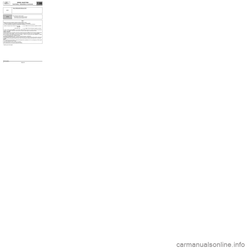
RAIL PRESSURE REGULATOR
NOTESThis command is used to check:
–the operation of the pressure regulator,
–and the high pressure injection circuit.
Step 1
Measure the pressure regulator resistance between tracks 1 and 2.
–Replace the regulator if its resistance is not approximately: 3 Ω ± 0.5 at 20˚C.
Check the continuity and absence of interference resistance of the following connections:
Injection computer brown 48-track connector B,
track M4track 2 of the rail pressure regulator connector
+ 12 V after relaytrack 1 of the rail pressure regulator connector
If, when running command AC011, you can hear a slight whistling noise and a crunching noise from the pressure
regulator, go to step 2. Otherwise, ensure that the computer output stage is functioning correctly:
Using a voltmeter:
With the solenoid valve connected, connect the voltmeter earth lead to track 2 of the fuel pressure solenoid valve
and the positive cable to track 1. Clear any fuel pressure solenoid valve faults, then run command AC011:
●The voltmeter should display two successive voltages: ~ 2.5 V for an opening cyclic ratio of 20% then ~ 8.75 V
for an opening cyclic ratio* of 70% (ten cycles).
Or using an oscilloscope (range 5 V/division and with time base 1 ms/division):
With the solenoid valve connected, connect the oscilloscope earth to the battery earth and the positive contact point
on track 2 of the fuel pressure solenoid valve; clear any fuel pressure solenoid valve faults then run command
AC011:
●the oscilloscope should display a square wave signal with an amplitude of 12.5 V at a frequency of 185 Hz (with
an OCR* passing from 20 to 70%).
If the measurement is correct, replace the regulator.
If the measurement is not correct, contact the Techline.
EDC16_V51_AC011
Page 222 of 273
DIESEL INJECTION
Fault finding – Customer complaints13B
13B - 222V3 MR-372-J84-13B250$810.mif
EDC16
PROGRAM NO.: C1
Vdiag No.: 51DIESEL INJECTION
Fault finding – Customer complaints
NOTESBefore dealing with this customer complaint, check that there are no faults, and the
conformity (or otherwise) of the parameters and statuses using the diagnostic tool.
If the customer complaint is not eliminated, then proceed according to the
corresponding fault finding chart.
NO DIALOGUE WITH ENGINE MANAGEMENT COMPUTER ALP1
STARTING FAULT OR STARTING IMPOSSIBLE ALP2
INJECTION NOISEALP3
POOR PERFORMANCEALP4
IRREGULAR ENGINE OPERATION ALP5
EXTERNAL LEAKS FROM THE FUEL CIRCUIT ALP6
ROUGH IDLEALP7
OIL LEAKS FROM THE TURBOCHARGER ALP8
TURBOCHARGER NOISESALP9
SMOKE FROM THE EXHAUSTALP10
MR-372-J84-13B250$810.mif