Page 135 of 4331
AT-130< SERVICE INFORMATION >
DTC P0744 A/T TCC S/V FUNCTION (LOCK-UP)
5. Accelerate vehicle to more than 80 km/h (50 MPH) and maintain the following conditions continuously until “TESTING” has turned to “COMPLETE”. (It wi ll take approximately 30 seconds after “TESTING”
shows.)
THROTTLE POSI: 1.0/8 - 2.0/8 (at all times during step 4)
SLCT LVR POSI: “D” position
TCC S/V DUTY: More than 94%
VEHICLE SPEED: Constant speed of more than 80 km/h (50 MPH)
- Make sure that “GEAR” shows “4”.
- For shift schedule, refer to AT-64, " Vehicle Speed at Which Gear Shifting Occurs " .
- If “TESTING” does not ap pear on CONSULT-III for a long ti me, select “SELF-DIAG RESULTS”. In
case a DTC other than “P0744 A/T TCC S/ V FNCTN” is shown, refer to AT-79, " CONSULT-III Func-
tion (TRANSMISSION) " .
6. Make sure that “OK” is displayed. (If “NG” is displayed, refer to “DIAGNOSTIC PROCEDURE”.)
Refer to AT-130, " Diagnosis Procedure " .
Refer to AT-64, " Vehicle Speed at Which Lock-up Occurs/Releases " .
WITH GST
Follow the procedure “WITH CONSULT-III”.
Diagnosis Procedure INFOID:00000000043054021.
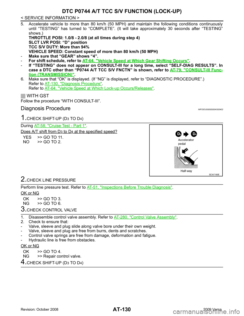
CHECK SHIFT-UP (D 3 TO D 4)
During AT-58, " Cruise Test - Part 1 " .
Does A/T shift from D 3 to D 4 at the specified speed?
YES >> GO TO 11.
NO >> GO TO 2. 2.
CHECK LINE PRESSURE
Perform line pressure test. Refer to AT-51, " Inspections Before Trouble Diagnosis " .
OK or NG OK >> GO TO 3.
NG >> GO TO 6. 3.
CHECK CONTROL VALVE
1. Disassemble control valve assembly. Refer to AT-280, " Control Valve Assembly " .
2. Check to ensure that:
- Valve, sleeve and plug slide along valve bore under their own weight.
- Valve, sleeve and plug are free from burrs, dents and scratches.
- Control valve springs are free from damage, deformation and fatigue.
- Hydraulic line is free from obstacles.
OK or NG OK >> GO TO 4.
NG >> Repair control valve. 4.
CHECK SHIFT-UP (D 3 TO D 4) SCIA7190E
Page 136 of 4331
DTC P0744 A/T TCC S/
V FUNCTION (LOCK-UP)
AT-131
< SERVICE INFORMATION >
D
E
F
G H
I
J
K L
M A
B AT
N
O P
During
AT-58, " Cruise Test - Part 1 " .
Does A/T shift from D 3 to D 4 at the specified speed?
YES >> GO TO 5.
NO >> Check control valve again. Repair or replace control valve assembly. 5.
CHECK DTC
Perform AT-129, " DTC Confirmation Procedure " .
OK or NG OK >>
INSPECTION END
NG >> GO TO 11. Check for proper lock-up. 6.
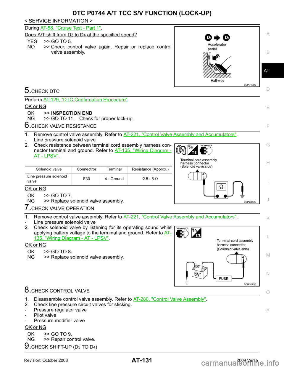
CHECK VALVE RESISTANCE
1. Remove control valve assembly. Refer to AT-221, " Control Valve Assembly and Accumulators " .
- Line pressure solenoid valve
2. Check resistance between terminal cord assembly harness con- nector terminal and ground. Refer to AT-135, " Wiring Diagram -
AT - LPSV " .
OK or NG OK >> GO TO 7.
NG >> Replace solenoid valve assembly. 7.
CHECK VALVE OPERATION
1. Remove control valve assembly. Refer to AT-221, " Control Valve Assembly and Accumulators " .
- Line pressure solenoid valve
2. Check solenoid valve by listening for its operating sound while
applying battery voltage to the terminal and ground. Refer to AT-135, " Wiring Diagram - AT - LPSV " .
OK or NG OK >> GO TO 8.
NG >> Replace solenoid valve assembly. 8.
CHECK CONTROL VALVE
1. Disassemble control valve assembly. Refer to AT-280, " Control Valve Assembly " .
2. Check line pressure circuit valves for sticking.
- Pressure regulator valve
- Pilot valve
- Pressure modifier valve
OK or NG OK >> GO TO 9.
NG >> Repair control valve. 9.
CHECK SHIFT-UP (D 3 TO D 4) SCIA7190E
Solenoid valve Connectror Terminal Resistance (Approx.)
Line pressure solenoid
valve F30 4 - Ground 2.5 - 5
Ω SCIA3457E
SCIA3275E
Page 137 of 4331
AT-132< SERVICE INFORMATION >
DTC P0744 A/T TCC S/V FUNCTION (LOCK-UP)
During AT-58, " Cruise Test - Part 1 " .
Does A/T shift from D 3 to D 4 at the specified speed?
YES >> GO TO 10.
NO >> Check control valve again. Repair or replace control valve assembly. 10.
CHECK DTC
Perform AT-129, " DTC Confirmation Procedure " .
OK or NG OK >>
INSPECTION END
NG >> GO TO 11. Check for proper lock-up. 11.
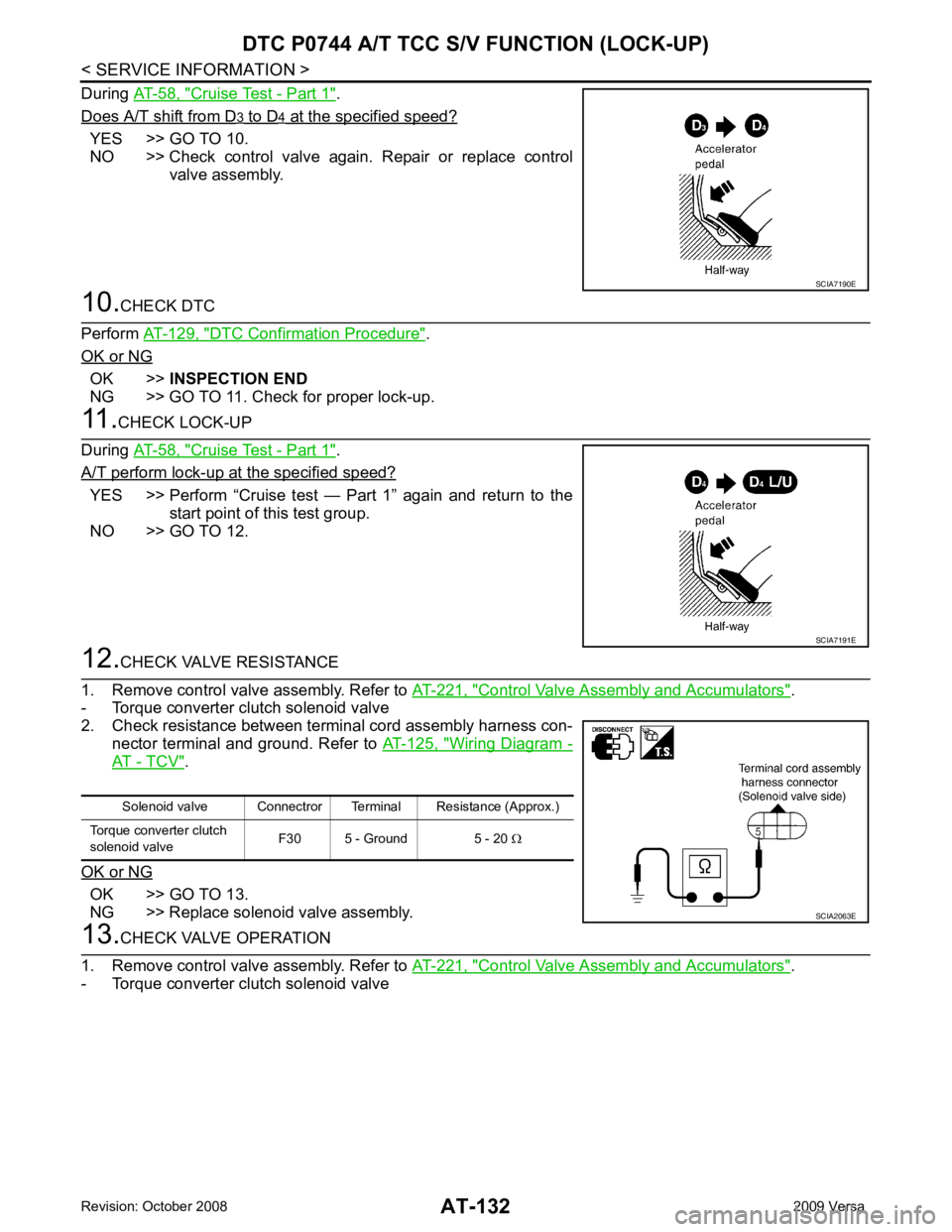
CHECK LOCK-UP
During AT-58, " Cruise Test - Part 1 " .
A/T perform lock-up at the specified speed? YES >> Perform “Cruise test — Part 1” again and return to the
start point of this test group.
NO >> GO TO 12. 12.
CHECK VALVE RESISTANCE
1. Remove control valve assembly. Refer to AT-221, " Control Valve Assembly and Accumulators " .
- Torque converter clutch solenoid valve
2. Check resistance between terminal cord assembly harness con-
nector terminal and ground. Refer to AT-125, " Wiring Diagram -
AT - TCV " .
OK or NG OK >> GO TO 13.
NG >> Replace solenoid valve assembly. 13.
CHECK VALVE OPERATION
1. Remove control valve assembly. Refer to AT-221, " Control Valve Assembly and Accumulators " .
- Torque converter clutch solenoid valve SCIA7190E
SCIA7191E
Solenoid valve Connectror Terminal Resistance (Approx.)
Torque converter clutch
solenoid valve F30 5 - Ground 5 - 20
Ω SCIA2063E
Page 138 of 4331
DTC P0744 A/T TCC S/
V FUNCTION (LOCK-UP)
AT-133
< SERVICE INFORMATION >
D
E
F
G H
I
J
K L
M A
B AT
N
O P
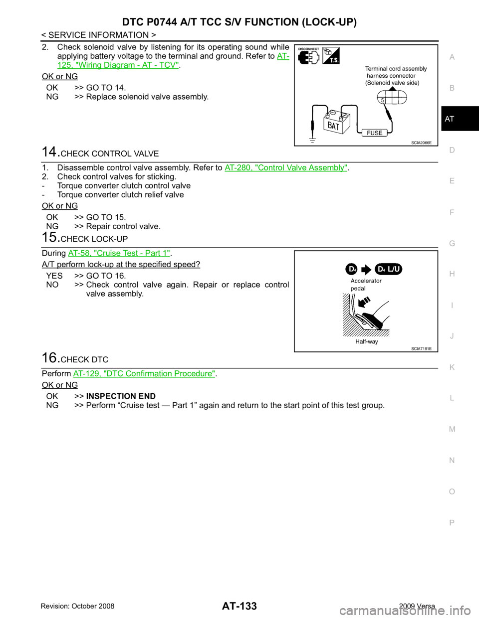
2. Check solenoid valve by listening for its operating sound while
applying battery voltage to the terminal and ground. Refer to AT-125, " Wiring Diagram - AT - TCV " .
OK or NG OK >> GO TO 14.
NG >> Replace solenoid valve assembly. 14.
CHECK CONTROL VALVE
1. Disassemble control valve assembly. Refer to AT-280, " Control Valve Assembly " .
2. Check control valves for sticking.
- Torque converter clutch control valve
- Torque converter clutch relief valve
OK or NG OK >> GO TO 15.
NG >> Repair control valve. 15.
CHECK LOCK-UP
During AT-58, " Cruise Test - Part 1 " .
A/T perform lock-up at the specified speed? YES >> GO TO 16.
NO >> Check control valve again. Repair or replace control
valve assembly. 16.
CHECK DTC
Perform AT-129, " DTC Confirmation Procedure " .
OK or NG OK >>
INSPECTION END
NG >> Perform “Cruise test — Part 1” again and re turn to the start point of this test group. SCIA2066E
SCIA7191E
Page 143 of 4331
AT-138< SERVICE INFORMATION >
DTC P0745 LINE PRESS
URE SOLENOID VALVE
NG >> GO TO 6. 6.
CHECK TCM
1. Check TCM input/output signal. Refer to AT-77, " TCM Terminal and Reference Value " .
2. If NG, recheck TCM pin terminals for damage or loose connection with harness connector.
OK or NG OK >>
INSPECTION END
NG >> Repair or replace damaged parts.
Component Inspection INFOID:0000000004305410
LINE PRESSURE SOLENOID VALVE
• For removal, refer to AT-221, " Control Valve Assembly and Accumulators " .
Resistance Check
• Check resistance between terminal and ground.
Operation Check
• Check solenoid valve by listening for its operating sound while applying battery voltage to the terminal and ground.
DROPPING RESISTOR
• Check resistance between terminals. Solenoid valve Connector Terminal Resistance (Approx.)
Line pressure solenoid
valve F30 4 - Ground 2.5 - 5
Ω SCIA3457E
SCIA3275E
Item Connector Terminal Resistance (Approx.)
Dropping resistor E49 1 - 2 12 Ω SCIA4950E
Page 147 of 4331
OK >> GO TO 4.
NG >> Repair open circuit or short to ground or short to power in harness or connectors. OK >> GO TO 5.
NG >> Repair or replace damaged parts. DTC Confirmation Procedure " .
OK or NG OK >>
INSPECTION END
NG >> GO TO 6. TCM Terminal and Reference Value " .
2. If NG, recheck TCM pin terminals for damage or loose connection with harness connector.
OK or NG OK >>
INSPECTION END
NG >> Repair or replace damaged parts.
Component Inspection INFOID:0000000004305418
SHIFT SOLENOID VALVE A
• For removal, refer to AT-221, " Control Valve Assembly and Accumulators " .
Resistance Check Item Connector Terminal Continuity
TCM E31 11 Yes
Terminal cord assembly
harness connector F30 2
Page 152 of 4331
AT
N
O P
3. Check continuity between terminal cord assembly harness con-
nector terminal and TCM connector terminal.
4. If OK, check harness for short to ground and short to power.
5. If OK, check continuity between ground and transaxle assembly.
6. Reinstall any part removed.
OK or NG OK >> GO TO 4.
NG >> Repair open circuit or short to ground or short to power in harness or connectors. OK >> GO TO 5.
NG >> Repair or replace damaged parts. DTC Confirmation Procedure " .
OK or NG OK >>
INSPECTION END
NG >> GO TO 6. TCM Terminal and Reference Value " .
2. If NG, recheck TCM pin terminals for dam age or loose connection with harness connector.
OK or NG OK >>
INSPECTION END
NG >> Repair or replace damaged parts.
Component Inspection INFOID:0000000004305426
SHIFT SOLENOID VALVE B • For removal, refer to AT-221, " Control Valve Assembly and Accumulators " .
Resistance Check Item Connector Terminal Continuity
TCM E31 12 Yes
Terminal cord assembly
harness connector F30 1
Page 154 of 4331
AT
N
O P
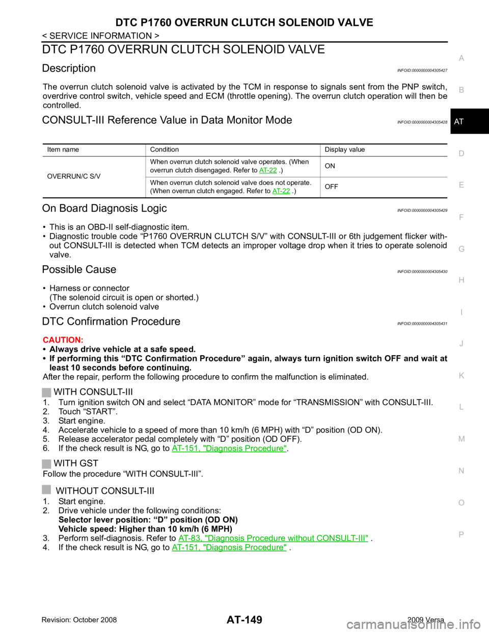
DTC P1760 OVERRUN CLUTCH SOLENOID VALVE
Description INFOID:0000000004305427
The overrun clutch solenoid valve is activated by the TCM in response to signals sent from the PNP switch,
overdrive control switch, vehicle speed and ECM (throt tle opening). The overrun clutch operation will then be
controlled.
CONSULT-III Reference Val ue in Data Monitor Mode INFOID:0000000004305428
On Board Diagnosis Logic INFOID:0000000004305429
• This is an OBD-II self-diagnostic item.
• Diagnostic trouble code “P1760 OVERRUN CLUTCH S/V” wit h CONSULT-III or 6th judgement flicker with-
out CONSULT-III is detected when TCM detects an im proper voltage drop when it tries to operate solenoid
valve.
Possible Cause INFOID:0000000004305430
• Harness or connector (The solenoid circuit is open or shorted.)
• Overrun clutch solenoid valve
DTC Confirmation Procedure INFOID:0000000004305431
CAUTION:
• Always drive vehicle at a safe speed.
• If performing this “DTC Confirmation Procedure” again, always turn ignition switch OFF and wait at
least 10 seconds before continuing.
After the repair, perform the following procedure to confirm the malfunction is eliminated.
WITH CONSULT-III
1. Turn ignition switch ON and select “DATA MO NITOR” mode for “TRANSMISSION” with CONSULT-III.
2. Touch “START”.
3. Start engine.
4. Accelerate vehicle to a speed of more than 10 km/h (6 MPH) with “D” position (OD ON).
5. Release accelerator pedal completely with “D” position (OD OFF).
6. If the check result is NG, go to AT-151, " Diagnosis Procedure " .
WITH GST
Follow the procedure “WITH CONSULT-III”.
WITHOUT CONSULT-III
1. Start engine.
2. Drive vehicle under the following conditions: Selector lever position: “D” position (OD ON)
Vehicle speed: Higher than 10 km/h (6 MPH)
3. Perform self-diagnosis. Refer to AT-83, " Diagnosis Procedure without CONSULT-III " .
4. If the check result is NG, go to AT-151, " Diagnosis Procedure " .
Item name Condition Display value
OVERRUN/C S/V When overrun clutch solenoid valve operates. (When
overrun clutch disengaged. Refer to AT-22 .)
ON
When overrun clutch solenoid valve does not operate.
(When overrun clutch engaged. Refer to AT-22 .)
OFF