Page 3942 of 4331
MTC
N
O P
THERMO CONTROL AMPLIFIER
Removal and Installation INFOID:0000000004307078
NOTE:
Only MR18DE - TYPE 2 systems are equipped with a thermo control amplifier.
REMOVAL 1. Remove evaporator. Refer to MTC-85, " Removal and Installation of Evaporator " .
CAUTION:
Cap or wrap the joint of the pipe with suitable ma terial such as vinyl tape to avoid the entry of air.
2. Mark the mounting position of the thermo control amp. and then remove thermo control amp. (1) from evaporator (2).
INSTALLATION Installation is in the reverse order of removal.
CAUTION:
• Replace O-rings for A/C piping with new on es, and apply compressor oil when installing.
• Install the thermo control amp. at the mark made during removal of the thermo control amp.
• When recharging refrigerant, check for leaks.
Page 3944 of 4331

MTC
N
O P
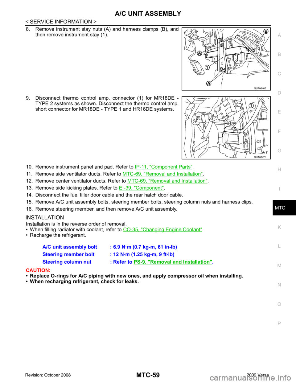
8. Remove instrument stay nuts (A) and harness clamps (B), and
then remove instrument stay (1).
9. Disconnect thermo control amp. connector (1) for MR18DE - TYPE 2 systems as shown. Disconnect the thermo control amp.
short connector for MR18DE - TYPE 1 and HR16DE systems.
10. Remove instrument panel and pad. Refer to IP-11, " Component Parts " .
11. Remove side ventilator ducts. Refer to MTC-69, " Removal and Installation " .
12. Remove center ventilator ducts. Refer to MTC-69, " Removal and Installation " .
13. Remove side kicking plates. Refer to EI-39, " Component " .
14. Disconnect the fuel filler door cable and the rear hatch door cable.
15. Remove A/C unit assembly bolts, steering member bolts, steering column nuts and harness clips.
16. Remove steering member, and then remove A/C unit assembly.
INSTALLATION Installation is in the reverse order of removal.
• When filling radiator with coolant, refer to CO-35, " Changing Engine Coolant " .
• Recharge the refrigerant.
CAUTION:
• Replace O-rings for A/C piping with new on es, and apply compressor oil when installing.
• When recharging refrigerant, check for leaks. Removal and Installation " .
Page 3960 of 4331
MTC
N
O P
7. Manifold gauge set (J-39183) A. Prefe
rred (best) method B. Alternative method
C. For charging
*1 MTC-17, " Maintenance of Oil Quanti-
ty in Compressor " *2
MTC-86, " Checking of Refrigerant
Leaks " *3
MTC-87, " Electronic Refrigerant
Leak Detector "
*4
MTC-45, " Insufficient Cooling "
Page 3963 of 4331
Precaution for Refrigerant Connection " .
Removal and Installation of Compressor - HR16DE INFOID:0000000004800722
HR16DE
REMOVAL
Page 3964 of 4331

MTC
N
O P
1. Use the recovery/recycling equipment
to evacuate the refrigerant. Refer to MTC-74, " HFC-134a (R-134a)
Service Procedure " .
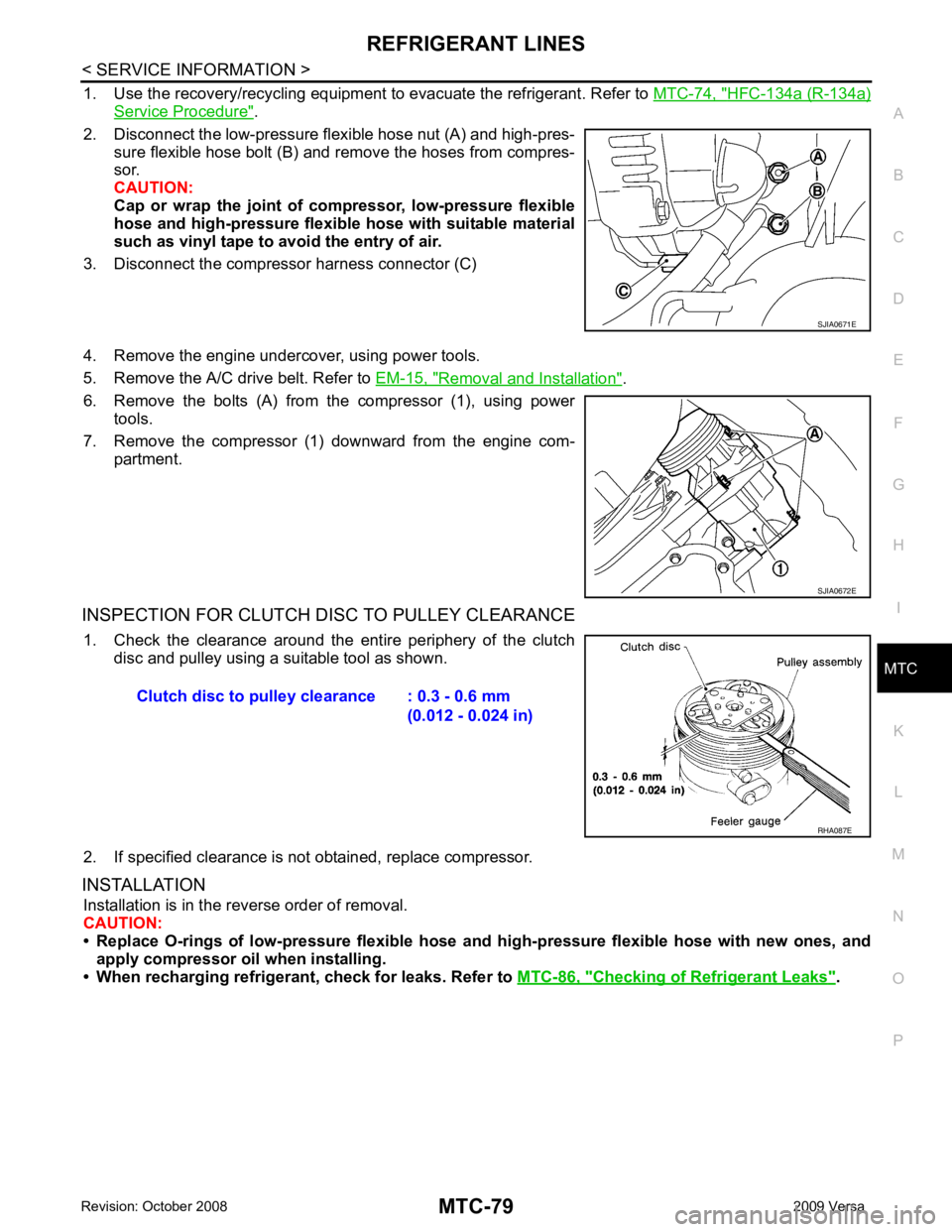
2. Disconnect the low-pressure flexible hose nut (A) and high-pres- sure flexible hose bolt (B) and remove the hoses from compres-
sor.
CAUTION:
Cap or wrap the joint of co mpressor, low-pressure flexible
hose and high-pressure flexible hose with suitable material
such as vinyl tape to avoid the entry of air.
3. Disconnect the compressor harness connector (C)
4. Remove the engine undercover, using power tools.
5. Remove the A/C drive belt. Refer to EM-15, " Removal and Installation " .
6. Remove the bolts (A) from the compressor (1), using power tools.
7. Remove the compressor (1) downward from the engine com- partment.
INSPECTION FOR CLUTCH DISC TO PULLEY CLEARANCE 1. Check the clearance around the entire periphery of the clutch disc and pulley using a suitable tool as shown.
2. If specified clearance is not obtained, replace compressor.
INSTALLATION Installation is in the reverse order of removal.
CAUTION:
• Replace O-rings of low-pressure flexible hose and high-pressure flexible hose with new ones, and
apply compressor oil when installing.
• When recharging refrigeran t, check for leaks. Refer to MTC-86, " Checking of Refrigerant Leaks " .
Page 3965 of 4331
HFC-134a (R-134a)
Service Procedure " .
2. Remove the nut (A) for the low-pressure flexible hose (1) and the bolt (B) for the high-pressure flexible hose (2) and remove
the hoses from the compressor.
CAUTION:
Cap or wrap the joint of co mpressor, low-pressure flexible
hose and high-pressure flexibl e hose with suitable material
such as vinyl tape to avoid the entry of air.
3. Remove the engine undercover, using power tools.
4. Remove A/C compressor belt. Refer to EM-136, " Removal and Installation " .
5. Disconnect compressor connector.
6. Remove bolts (A) from compressor (1), using power tools.
7. Remove compressor (1) downward from the engine compart- ment. SJIA0672E
Page 3966 of 4331

MTC
N
O P
INSPECTION FOR CLUTCH DISC TO PULLEY CLEARANCE
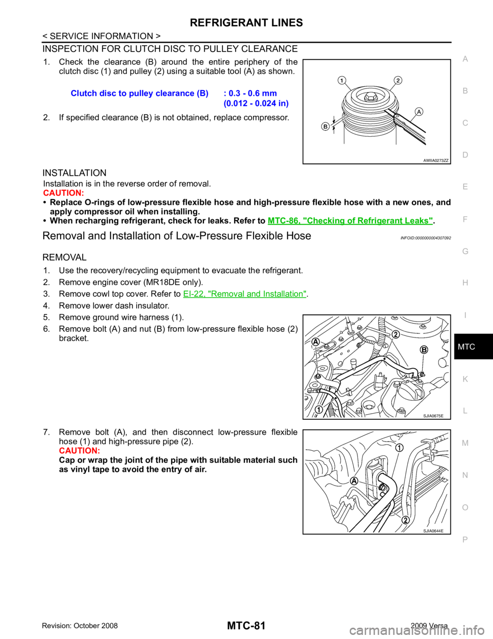
1. Check the clearance (B) around the entire periphery of the clutch disc (1) and pulley (2) usi ng a suitable tool (A) as shown.
2. If specified clearance (B) is not obtained, replace compressor.
INSTALLATION Installation is in the reverse order of removal.
CAUTION:
• Replace O-rings of low-pressure flexible hose and high-pressure flexible hose with a new ones, and
apply compressor oil when installing.
• When recharging refrigeran t, check for leaks. Refer to MTC-86, " Checking of Refrigerant Leaks " .
Removal and Installation of Low-Pressure Flexible Hose INFOID:0000000004307092
REMOVAL 1. Use the recovery/recycling equipment to evacuate the refrigerant.
2. Remove engine cover (MR18DE only).
3. Remove cowl top cover. Refer to EI-22, " Removal and Installation " .
4. Remove lower dash insulator.
5. Remove ground wire harness (1).
6. Remove bolt (A) and nut (B) from low-pressure flexible hose (2) bracket.
7. Remove bolt (A), and then disconnect low-pressure flexible hose (1) and high-pressure pipe (2).
CAUTION:
Cap or wrap the joint of the pi pe with suitable material such
as vinyl tape to avoid the entry of air. Clutch disc to pulley clearance (B) : 0.3 - 0.6 mm
(0.012 - 0.024 in)
Page 3968 of 4331

MTC
N
O P
Removal and Installation of High-Pressure Pipe
INFOID:0000000004307094
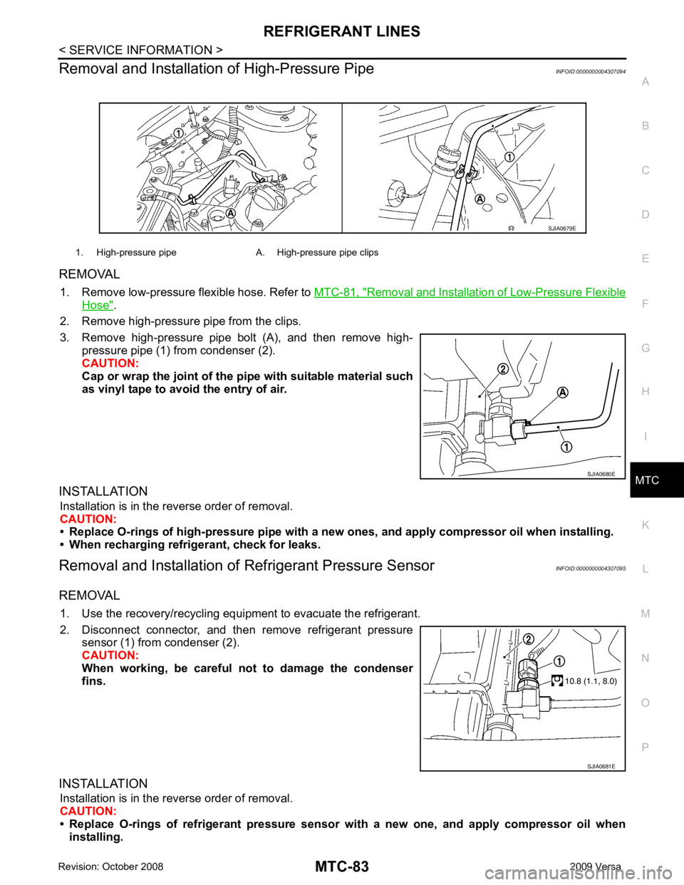
REMOVAL 1. Remove low-pressure flexible hose. Refer to MTC-81, " Removal and Installation of Low-Pressure Flexible
Hose " .
2. Remove high-pressure pipe from the clips.
3. Remove high-pressure pipe bolt (A), and then remove high- pressure pipe (1) from condenser (2).
CAUTION:
Cap or wrap the joint of the pi pe with suitable material such
as vinyl tape to avoid the entry of air.
INSTALLATION Installation is in the reverse order of removal.
CAUTION:
• Replace O-rings of high-pressure pipe with a ne w ones, and apply compressor oil when installing.
• When recharging refrigerant, check for leaks.
Removal and Installation of Refrigerant Pressure Sensor INFOID:0000000004307095
REMOVAL 1. Use the recovery/recycling equipment to evacuate the refrigerant.
2. Disconnect connector, and then remove refrigerant pressure sensor (1) from condenser (2).
CAUTION:
When working, be careful not to damage the condenser
fins.
INSTALLATION Installation is in the reverse order of removal.
CAUTION:
• Replace O-rings of refrigerant pressure senso r with a new one, and apply compressor oil when
installing. 1. High-pressure pipe A. High-pressure pipe clips