2009 NISSAN TIIDA compressor
[x] Cancel search: compressorPage 3144 of 4331
EM
NP
O
24. Remove A/C compressor with piping connected from t
he engine. Temporarily secure it on the vehicle side
with a rope to avoid putting load on it. Refer to MTC-80, " Removal and Installation of Compressor -
MR18DE " .
25. Remove the intake manifold to prevent the hanging chain from interfering. Refer to EM-141, " Compo-
nent " .
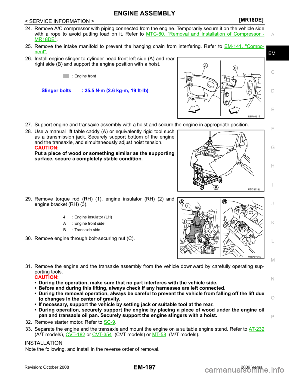
26. Install engine slinger to cylinder head front left side (A) and rear right side (B) and support the engine position with a hoist.
27. Support engine and transaxle assembly with a hoist and secure the engine in appropriate position.
28. Use a manual lift table caddy (A) or equivalently rigid tool such as a transmission jack. Securely support bottom of the engine
and the transaxle, and simultaneously adjust hoist tension.
CAUTION:
Put a piece of wood or someth ing similar as the supporting
surface, secure a completely stable condition.
29. Remove torque rod (RH) (1), engine insulator (RH) (2) and engine bracket (RH) (3).
30. Remove engine through bolt-securing nut (C).
31. Remove the engine and the transaxle assembly from the vehicle downward by carefully operating sup- porting tools.
CAUTION:
• During the operation, make sure that no part interferes with the vehicle side.
• Before and during this lifting, alw ays check if any harnesses are left connected.
• During the removal operation, alw ays be careful to prevent the vehicle from falling off the lift due
to changes in the center of gravity.
• If necessary, support the vehicle by setting jack or suitable tool at the rear.
• During operation, securely suppor t the engine by placing a piece of wood under the engine oil
pan and transaxle oil pan. Securely sup port the engine slingers with a hoist.
32. Remove starter motor. Refer to SC-9 .
33. Separate the engine and the transaxle and mount the engine on a suitable engine stand. Refer to AT-232(A/T models),
CVT-182 or
CVT-354 (CVT models) or
MT-58 (M/T models).
INSTALLATION Note the following, and install in the reverse order of removal. : Engine front
Slinger bolts : 25.5 N·m (2.6 kg-m, 19 ft-lb) PBIC3223J
Page 3247 of 4331
FSU
N
O P
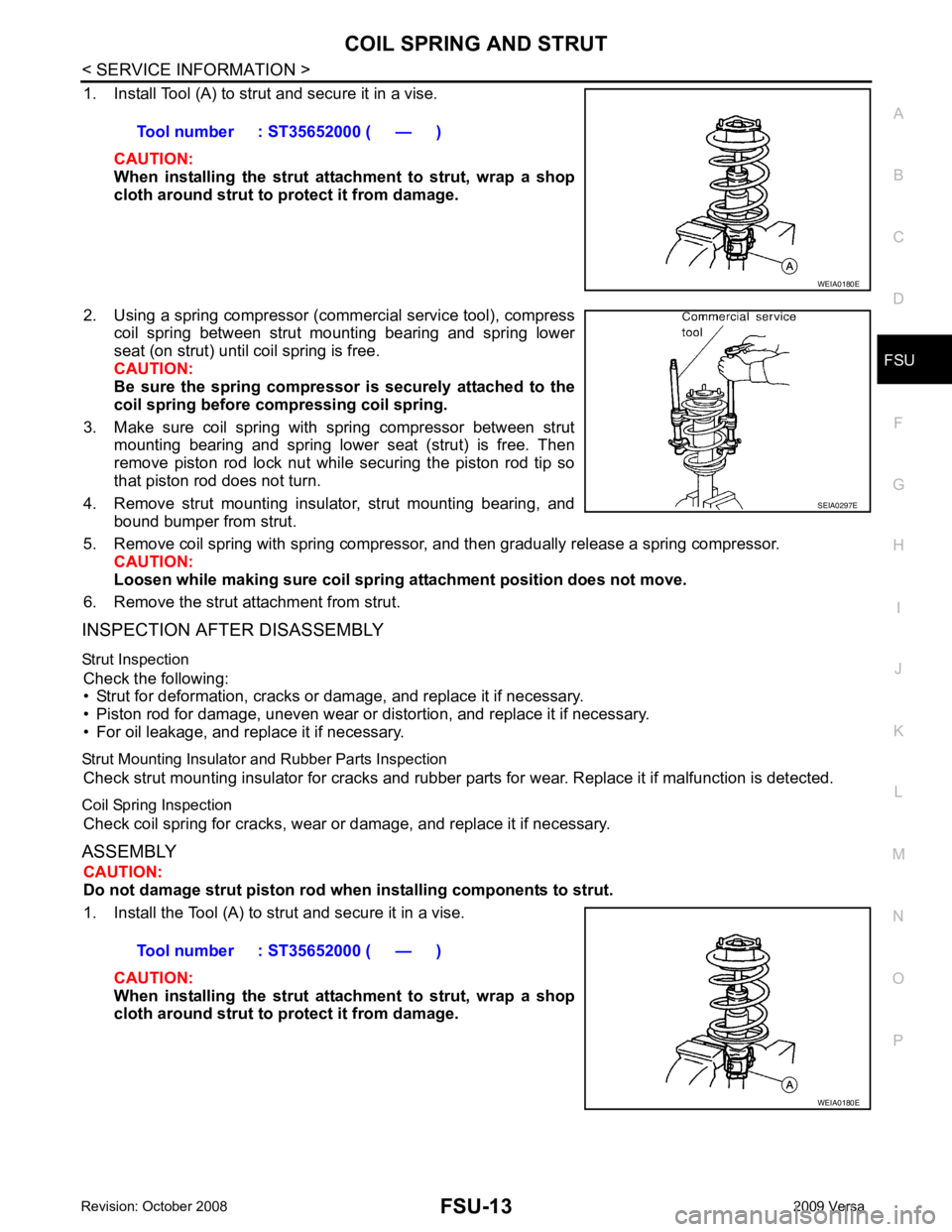
1. Install Tool (A) to strut and secure it in a vise.
CAUTION:
When installing the strut att achment to strut, wrap a shop
cloth around strut to protect it from damage.
2. Using a spring compressor (commercial service tool), compress coil spring between strut mounting bearing and spring lower
seat (on strut) until coil spring is free.
CAUTION:
Be sure the spring compressor is securely attached to the
coil spring before co mpressing coil spring.
3. Make sure coil spring with spring compressor between strut mounting bearing and spring lower seat (strut) is free. Then
remove piston rod lock nut while securing the piston rod tip so
that piston rod does not turn.
4. Remove strut mounting insulator, strut mounting bearing, and bound bumper from strut.
5. Remove coil spring with spring compressor, and then gradually release a spring compressor. CAUTION:
Loosen while making sure coil spring attachment position does not move.
6. Remove the strut attachment from strut.
INSPECTION AFTER DISASSEMBLY
Strut Inspection Check the following:
• Strut for deformation, cracks or damage, and replace it if necessary.
• Piston rod for damage, uneven wear or di stortion, and replace it if necessary.
• For oil leakage, and replace it if necessary.
Strut Mounting Insulator and Rubber Parts Inspection Check strut mounting insulator for cracks and rubber part s for wear. Replace it if malfunction is detected.
Coil Spring Inspection Check coil spring for cracks, wear or damage, and replace it if necessary.
ASSEMBLY CAUTION:
Do not damage strut piston rod when installing components to strut.
1. Install the Tool (A) to strut and secure it in a vise.
CAUTION:
When installing the strut att achment to strut, wrap a shop
cloth around strut to protect it from damage. Tool number : ST35652000 ( — )
SEIA0297E
Page 3248 of 4331
FSU-14< SERVICE INFORMATION >
COIL SPRING AND STRUT
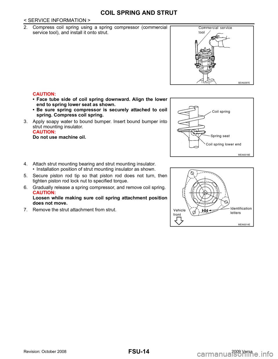
2. Compress coil spring using a spring compressor (commercial service tool), and install it onto strut.
CAUTION:
• Face tube side of coil spri ng downward. Align the lower
end to spring lower seat as shown.
• Be sure spring compressor is securely attached to coil
spring. Compress coil spring.
3. Apply soapy water to bound bumper. Insert bound bumper into strut mounting insulator.
CAUTION:
Do not use machine oil.
4. Attach strut mounting bearing and strut mounting insulator. • Installation position of strut mounting insulator as shown.
5. Secure piston rod tip so that piston rod does not turn, then tighten piston rod lock nut to specified torque.
6. Gradually release a spring compressor, and remove coil spring. CAUTION:
Loosen while making sure co il spring attachment position
does not move.
7. Remove the strut attachment from strut. SEIA0297E
MEIA0016E
MEIA0014E
Page 3759 of 4331
MA-16< SERVICE INFORMATION >
ENGINE MAINTENANCE (HR16DE)
ENGINE MAINTENANCE (HR16DE)
DRIVE BELT
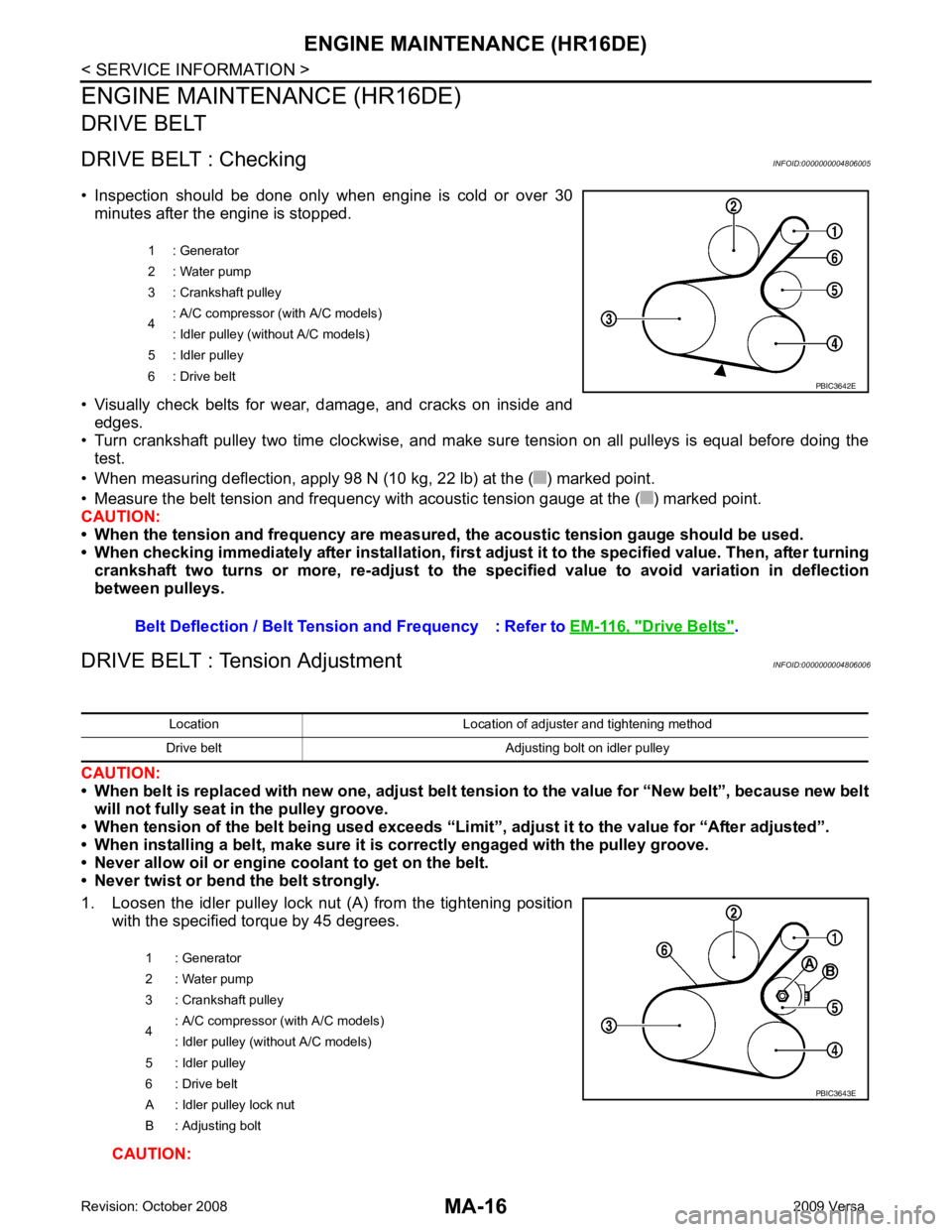
DRIVE BELT : Checking INFOID:0000000004806005
• Inspection should be done only when engine is cold or over 30 minutes after the engine is stopped.
• Visually check belts for wear, damage, and cracks on inside and edges.
• Turn crankshaft pulley two time clockwise, and make sure tension on all pulleys is equal before doing the test.
• When measuring deflection, apply 98 N (10 kg, 22 lb) at the ( ) marked point.
• Measure the belt tension and frequency with acous tic tension gauge at the ( ) marked point.
CAUTION:
• When the tension and frequency are measured, the acoustic tension gauge should be used.
• When checking immediately after installation, first ad just it to the specified value. Then, after turning
crankshaft two turns or more, re-adjust to the sp ecified value to avoid variation in deflection
between pulleys.
DRIVE BELT : Tension Adjustment INFOID:0000000004806006
CAUTION:
• When belt is replaced with new one, adjust belt tension to the value for “New belt”, because new belt
will not fully seat in the pulley groove.
• When tension of the belt being used exceeds “Limit”, adjust it to the value for “After adjusted”.
• When installing a belt, make sure it is correctly engaged with the pulley groove.
• Never allow oil or engine coolant to get on the belt.
• Never twist or bend the belt strongly.
1. Loosen the idler pulley lock nut (A) from the tightening position with the specified torque by 45 degrees.
CAUTION: 1 : Generator
2 : Water pump
3 : Crankshaft pulley
4 : A/C compressor (with A/C models)
: Idler pulley (without A/C models)
5 : Idler pulley
6 : Drive belt
Belt Deflection / Belt Tension and Frequency : Refer to EM-116, " Drive Belts " . PBIC3642E
Location Location of adjuster and tightening method
Drive belt Adjusting bolt on idler pulley
1 : Generator
2 : Water pump
3 : Crankshaft pulley
4 : A/C compressor
(with A/C models)
: Idler pulley (without A/C models)
5 : Idler pulley
6 : Drive belt
A : Idler pulley lock nut
B : Adjusting bolt PBIC3643E
Page 3769 of 4331
MA-26< SERVICE INFORMATION >
ENGINE MAINTENANCE (MR18DE)
ENGINE MAINTENANCE (MR18DE)
DRIVE BELT
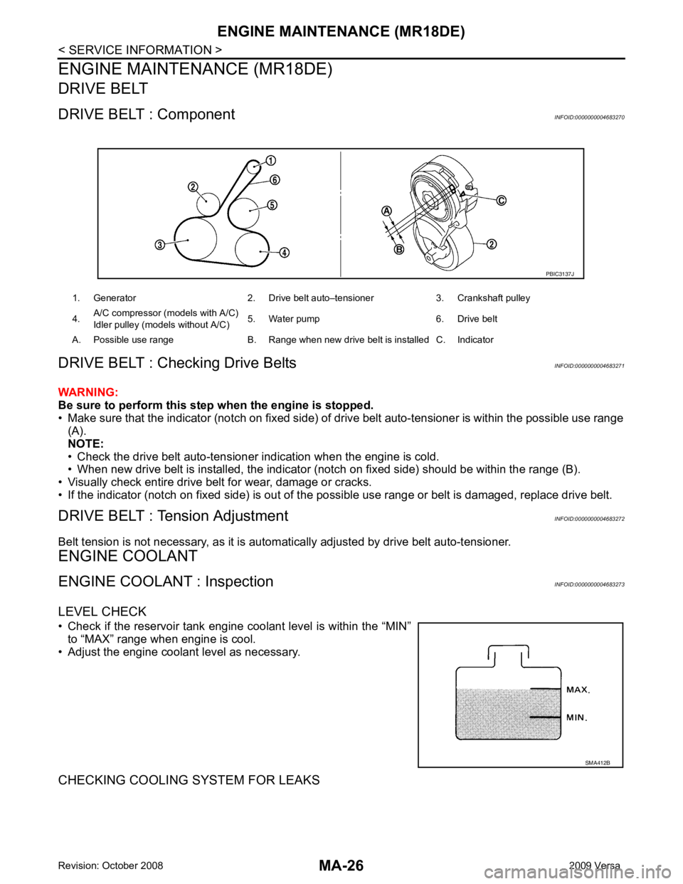
DRIVE BELT : Component INFOID:0000000004683270
DRIVE BELT : Checking Drive Belts INFOID:0000000004683271
WARNING:
Be sure to perform this step when the engine is stopped.
• Make sure that the indicator (notch on fixed side) of drive belt auto-tensioner is within the possible use range
(A).
NOTE:
• Check the drive belt auto-tensioner indication when the engine is cold.
• When new drive belt is installed, the indicator (notch on fixed side) should be within the range (B).
• Visually check entire drive belt for wear, damage or cracks.
• If the indicator (notch on fixed side) is out of t he possible use range or belt is damaged, replace drive belt.
DRIVE BELT : Tension Adjustment INFOID:0000000004683272
Belt tension is not necessary, as it is autom atically adjusted by drive belt auto-tensioner.
ENGINE COOLANT
ENGINE COOLANT : Inspection INFOID:0000000004683273
LEVEL CHECK
• Check if the reservoir tank engine coolant level is within the “MIN” to “MAX” range when engine is cool.
• Adjust the engine coolant level as necessary.
CHECKING COOLING SYSTEM FOR LEAKS 1. Generator 2. Drive belt auto–tensioner 3. Crankshaft pulley
4. A/C compressor (models with A/C)
Idler pulley (models without A/C) 5. Water pump 6. Drive belt
A. Possible use range B. Range when new drive belt is installed C. Indicator PBIC3137J
SMA412B
Page 3886 of 4331

MTC
N
O P
CONTENTS
MANUAL AIR CONDITIONER
SERVICE INFORMATION .. ..........................3
PRECAUTIONS .............................................. .....3
Precaution for Supplemental Restraint System
(SRS) "AIR BAG" and "SEAT BELT PRE-TEN-
SIONER" ............................................................. ......
3
Precaution Necessary fo r Steering Wheel Rota-
tion After Battery Disconnect ............................... ......
3
Precaution for Procedure without Cowl Top Cover ......4
Precaution for Working with HFC-134a (R-134a) ......4
General Refrigerant Precaution .......................... ......4
Oil Precaution ...................................................... ......5
Precaution for Refrigeran t Connection ......................5
Precaution for Service of Compressor ................ ......7
Precaution for Service Equipment ....................... ......8
Precaution for Leak Detection Dye ..................... ......9
PREPARATION .............................................. ....11
HFC-134a (R-134a) Service Tool and Equipment ....11
Commercial Service Tool .................................... ....13
REFRIGERATION SYSTEM .......................... ....15
Refrigerant Cycle ................................................ ....15
Refrigerant System Protec tion ................................15
Component Part Location ................................... ....16
OIL .................................................................. ....17
Maintenance of Oil Quantity in Compressor ....... ....17
AIR CONDITIONER CONTROL ..................... ....19
Control Operation ................................................ ....19
Discharge Air Flow .............................................. ....20
System Description ............................................. ....20
TROUBLE DIAGNOSIS ................................. ....22
CONSULT-II Function (BCM) .............................. ....22
How to Perform Trouble Diagnosis for Quick and
Accurate Repair ........... ...........................................
22
Component Parts and Harness Connector Loca-
tion ...................................................................... ....
23
Schematic ........................................................... ....25
Wiring Diagram - Heater - ................................... ....26 Wiring Diagram - A/C,M - ....................................
....27
Operational Check ............................................... ....30
Mode Door ........................................................... ....31
Air Mix Door ......................................................... ....32
Intake Door .......................................................... ....33
Front Blower Motor Circuit .......................................33
Magnet Clutch Circuit (If Equipped) ..................... ....37
Insufficient Cooling .............................................. ....45
Insufficient Heating .............................................. ....52
Noise ................................................................... ....53
CONTROLLER .................................................. 55
Removal and Installation ..................................... ....55
Disassembly and Assembly ................................. ....56
THERMO CONTROL AMPLIFIER .................... 57
Removal and Installation ..................................... ....57
A/C UNIT ASSEMBLY ...................................... 58
Removal and Installation ..................................... ....58
Disassembly and Assembly ................................. ....60
BLOWER MOTOR ............................................ 62
Removal and Installation ..................................... ....62
INTAKE DOOR .................................................. 63
Intake Door Cable Adjustment ............................. ....63
AIR MIX DOOR ................................................. 64
Air Mix Door Cable Adjustment ........................... ....64
MODE DOOR .................................................... 65
Mode Door Cable Adjustment ............................. ....65
BLOWER FAN RESISTOR ............................... 66
Removal and Installation ..................................... ....66
HEATER CORE ................................................. 67
Removal and Installation ..................................... ....67
AIR CONDITIONER FILTER ............................. 68
Removal and Installation ..................................... ....68
Page 3889 of 4331
MTC-4< SERVICE INFORMATION >
PRECAUTIONS
5. When the repair work is completed, return the ignition switch to the ″LOCK ″ position before connecting
the battery cables. (At this time, the steering lock mechanism will engage.)
6. Perform a self-diagnosis check of a ll control units using CONSULT-III.
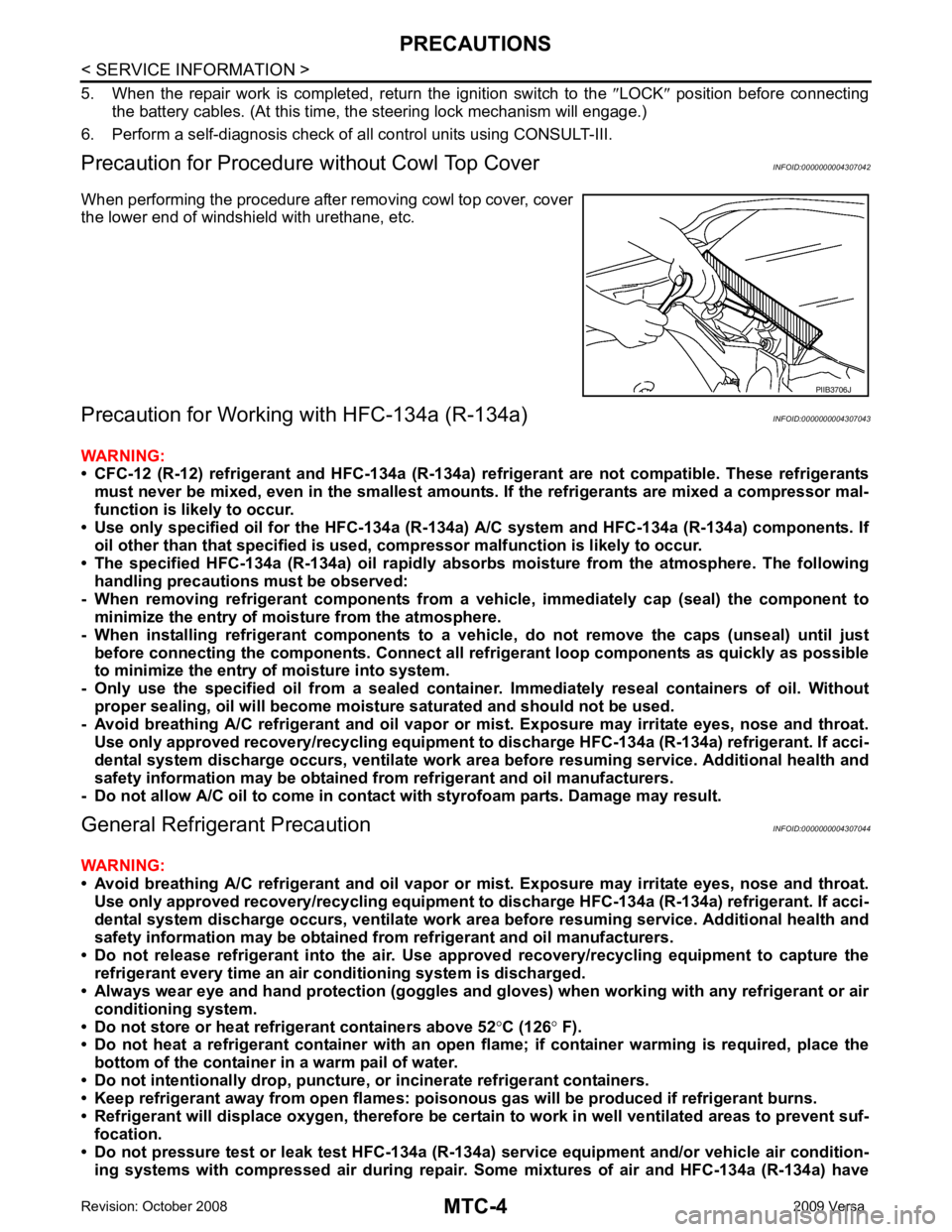
Precaution for Procedure without Cowl Top Cover INFOID:0000000004307042
When performing the procedure after removing cowl top cover, cover
the lower end of windshield with urethane, etc.
Precaution for Working with HFC-134a (R-134a) INFOID:0000000004307043
WARNING:
• CFC-12 (R-12) refrigerant and HFC-134a (R-134a) re frigerant are not compatible. These refrigerants
must never be mixed, even in the smallest amounts. If the refrigerants are mixed a compressor mal-
function is likely to occur.
• Use only specified oil for the HFC-134a (R-134a) A/C system and HFC-134a (R-134a) components. If
oil other than that specifi ed is used, compressor malf unction is likely to occur.
• The specified HFC-134a (R-134a) oi l rapidly absorbs moisture from the atmosphere. The following
handling precautions must be observed:
- When removing refrigerant components from a vehicle, immediately cap (seal) the component to
minimize the entry of moisture from the atmosphere.
- When installing refrigerant co mponents to a vehicle, do not remove the caps (unseal) until just
before connecting the components . Connect all refrigerant loop components as quickly as possible
to minimize the entry of moisture into system.
- Only use the specified oil from a sealed container. Immediately reseal containers of oil. Without
proper sealing, oil will become moisture saturat ed and should not be used.
- Avoid breathing A/C refrigerant and oil vapor or mist. Exposure may irritate eyes, nose and throat.
Use only approved recovery/recycling equipment to discharge HFC-134a (R-134a) refrigerant. If acci-
dental system discharge occurs, ventilate work area before resuming service. Additional health and
safety information may be obtained fr om refrigerant and oil manufacturers.
- Do not allow A/C oil to come in contact with styrofoam parts. Damage may result.
General Refrigerant Precaution INFOID:0000000004307044
WARNING:
• Avoid breathing A/C refrigerant and oil vapor or mist. Exposure may irritate eyes, nose and throat.
Use only approved recovery/recycling equipment to discharge HFC-134a (R-134a) refrigerant. If acci-
dental system discharge occurs, ventilate work area before resuming service. Additional health and
safety information may be obtained fr om refrigerant and oil manufacturers.
• Do not release refrigerant into th e air. Use approved recovery/recycling equipment to capture the
refrigerant every time an air conditioning system is discharged.
• Always wear eye and hand protection (goggles and gloves) when working with any refrigerant or air
conditioning system.
• Do not store or heat refrigerant containers above 52 °C (126 ° F).
• Do not heat a refrigerant container with an open flame; if container warming is required, place the
bottom of the container in a warm pail of water.
• Do not intentionally drop, puncture, or incinerate refrigerant containers.
• Keep refrigerant away from open flames: poisonou s gas will be produced if refrigerant burns.
• Refrigerant will displace oxygen, therefore be certa in to work in well ventilated areas to prevent suf-
focation.
• Do not pressure test or leak test HFC-134a (R-134a) service equipment and/or vehicle air condition-
ing systems with compressed air during repair. Some mixtures of air and HFC-134a (R-134a) have PIIB3706J
Page 3892 of 4331
MTC
N
O P
O-Ring Part Numbers and Specifications
CAUTION:
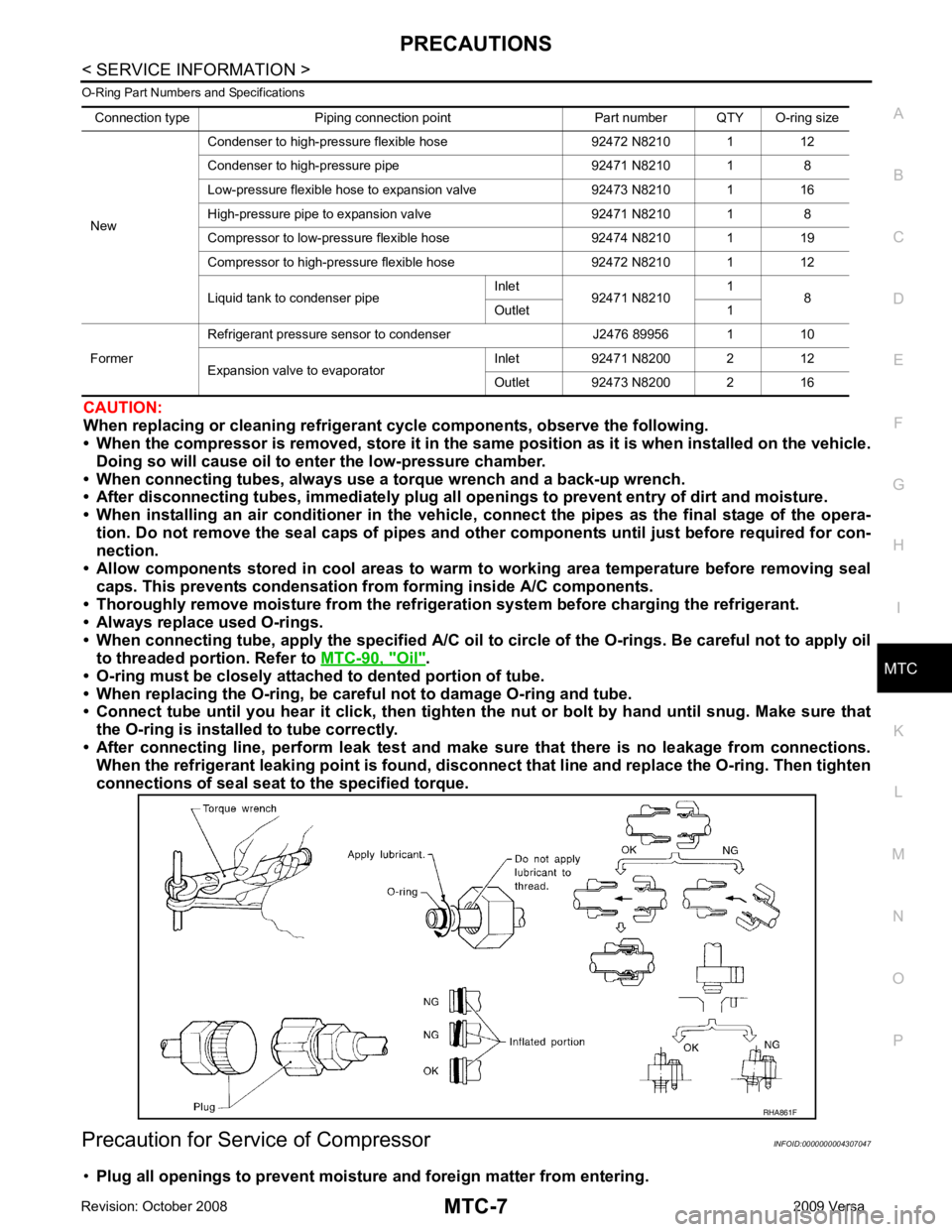
When replacing or cleaning refrigerant cycle components, observe the following.
• When the compressor is removed, store it in the sam e position as it is when installed on the vehicle.
Doing so will cause oil to en ter the low-pressure chamber.
• When connecting tubes, always use a to rque wrench and a back-up wrench.
• After disconnecting tubes, immediately plug all op enings to prevent entry of dirt and moisture.
• When installing an air conditione r in the vehicle, connect the pipes as the final stage of the opera-
tion. Do not remove the seal caps of pipes and other components until just before required for con-
nection.
• Allow components stored in cool areas to warm to working area temperature before removing seal
caps. This prevents condensation from forming inside A/C components.
• Thoroughly remove moisture from the refriger ation system before charging the refrigerant.
• Always replace used O-rings.
• When connecting tube, apply the speci fied A/C oil to circle of the O-rings. Be careful not to apply oil
to threaded portion. Refer to MTC-90, " Oil " .
• O-ring must be closely attached to dented portion of tube.
• When replacing the O-ring, be careful not to damage O-ring and tube.
• Connect tube until you hear it cl ick, then tighten the nut or bolt by hand until snug. Make sure that
the O-ring is installed to tube correctly.
• After connecting line, perform leak test and make sure that there is no leakage from connections.
When the refrigerant leaking point is found, disconnect that line and replace the O-ring. Then tighten
connections of seal seat to the specified torque.
Precaution for Service of Compressor INFOID:0000000004307047
• Plug all openings to prevent moisture and foreign matter from entering.
Connection type Piping connection point Part number QTY O-ring size
New Condenser to high-pressure flexible hose 92472 N8210 1 12
Condenser to high-pressure pipe 92471 N8210 1 8
Low-pressure flexible hose to expansion valve 92473 N8210 1 16
High-pressure pipe to expansion valve 92471 N8210 1 8
Compressor to low-pressure flexible hose 92474 N8210 1 19
Compressor to high-pressure flexible hose 92472 N8210 1 12
Liquid tank to condenser pipe Inlet
92471 N8210 1
8
Outlet 1
Former Refrigerant pressure sensor to condenser J2476 89956 1 10
Expansion valve to evaporator Inlet 92471 N8200 2 12
Outlet 92473 N8200 2 16