2009 NISSAN TIIDA compressor
[x] Cancel search: compressorPage 2483 of 4331

EC
NP
O
P/N POSI SW • Ignition switch: ON
Shift lever: P or N (A/T, CVT),
Neutral (M/T) ON
Shift lever: Except above OFF
PW/ST SIGNAL • Engine: After warming up, idle the
engine Steering wheel: Not being turned OFF
Steering wheel: Being turned ON
LOAD SIGNAL • Ignition switch: ON Rear window defogger switch: ON
and/or Lighting switch: 2nd ON
Rear window defogger switch and light-
ing switch: OFF OFF
IGNITION SW • Ignition switch: ON → OFF → ON ON → OFF → ON
HEATER FAN SW • Ignition switch: ON Heater fan: Operating ON
Heater fan: Not operating OFF
BRAKE SW • Ignition switch: ON Brake pedal: Fully released OFF
Brake pedal: Slightly depressed ON
INJ PULSE-B1 • Engine: After warming up
• Air conditioner switch: OFF
• Shift lever: P or N (A/T, CVT), Neutral (M/T)
• No load Idle 2.0 - 3.0 msec
2,000 rpm 1.9 - 2.9 msec
IGN TIMING • Engine: After warming up
• Air conditioner switch: OFF
• Shift lever: P or N (A/T, CVT), Neutral (M/T)
• No load Idle 8
° - 18 ° BTDC
2,000 rpm 25 ° - 45 ° BTDC
CAL/LD VALUE • Engine: After warming up
• Air conditioner switch: OFF
• Shift lever: P or N (A/T, CVT),
Neutral (M/T)
• No load Idle 10% - 35%
2,500 rpm 10% - 35%
MASS AIRFLOW • Engine: After warming up
• Air conditioner switch: OFF
• Shift lever: P or N (A/T, CVT), Neutral (M/T)
• No load Idle 1.0 - 4.0 g·m/s
2,500 rpm 2.0 - 10.0 g·m/s
PURG VOL C/V • Engine: After warming up
• Air conditioner switch: OFF
• Shift lever: P or N (A/T, CVT), Neutral (M/T)
• No load Idle
(Accelerator pedal is not depressed
even slightly, after engine starting) 0%
2,000 rpm 0 - 50%
INT/V TIM (B1) • Engine: After warming up
• Air conditioner switch: OFF
• Shift lever: P or N (A/T, CVT), Neutral (M/T)
• No load Idle
−5 ° - 5 °CA
When revving engine up to 2,000 rpm
quickly Approx. 0
° - 40 °CA
INT/V SOL (B1) • Engine: After warming up
• Air conditioner switch: OFF
• Shift lever: P or N (A/T, CVT),
Neutral (M/T)
• No load Idle 0% - 2%
When revving engine up to 2,000 rpm
quickly Approx. 0% - 90%
AIR COND RLY • Engine: After warming up, idle the
engine Air conditioner switch: OFF OFF
Air conditioner switch: ON
(Compressor operates) ON
FUEL PUMP RLY • For 1 second after turning ignition switch ON
• Engine running or cranking ON
• Except above conditions OFF
MONITOR ITEM CONDITION SPECIFICATION
Page 2765 of 4331

EC
NP
O
Cooling Fan Relay Operation
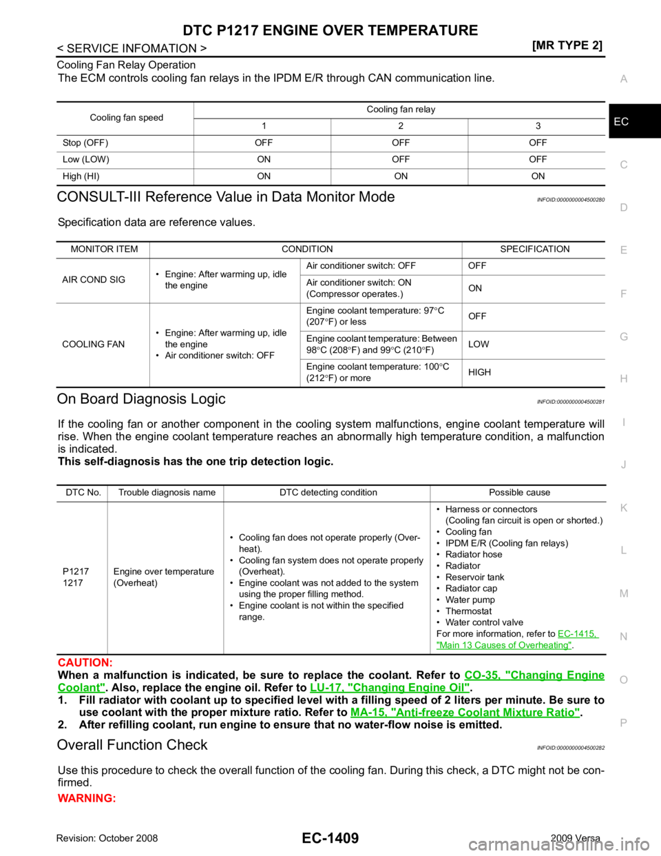
The ECM controls cooling fan relays in the IPDM E/R through CAN communication line.
CONSULT-III Reference Val ue in Data Monitor Mode INFOID:0000000004500280
Specification data are reference values.
On Board Diagnosis Logic INFOID:0000000004500281
If the cooling fan or another component in the cooli ng system malfunctions, engine coolant temperature will
rise. When the engine coolant temperature reaches an abnormally high temperature condition, a malfunction
is indicated.
This self-diagnosis has the on e trip detection logic.
CAUTION:
When a malfunction is in dicated, be sure to replace the coolant. Refer to CO-35, " Changing Engine
Coolant " . Also, replace the engine oil. Refer to
LU-17, " Changing Engine Oil " .
1. Fill radiator with coolant up to specified level with a filling speed of 2 liters per minute. Be sure to
use coolant with the proper mixture ratio. Refer to MA-15, " Anti-freeze Coolant Mixture Ratio " .
2. After refilling coolant, run engine to ensure that no water-flow noise is emitted.
Overall Function Check INFOID:0000000004500282
Use this procedure to check the overall function of the cooling fan. During this check, a DTC might not be con-
firmed.
WARNING: Cooling fan speed
Cooling fan relay
1 2 3
Stop (OFF) OFF OFF OFF
Low (LOW) ON OFF OFF
High (HI) ON ON ON MONITOR ITEM CONDITION SPECIFICATION
AIR COND SIG • Engine: After warming up, idle
the engine Air conditioner switch: OFF OFF
Air conditioner switch: ON
(Compressor operates.) ON
COOLING FAN • Engine: After warming up, idle
the engine
• Air conditioner switch: OFF Engine coolant temperature: 97
°C
(207 °F) or less OFF
Engine coolant temperature: Between
98 °C (208 °F) and 99 °C (210 °F) LOW
Engine coolant temperature: 100 °C
(212 °F) or more HIGHDTC No. Trouble diagnosis name DTC detecting condition Possible cause
P1217
1217 Engine over temperature
(Overheat) • Cooling fan does not operate properly (Over-
heat).
• Cooling fan system does not operate properly (Overheat).
• Engine coolant was not added to the system using the proper filling method.
• Engine coolant is not within the specified
range. • Harness or connectors
(Cooling fan circuit is open or shorted.)
• Cooling fan
• IPDM E/R (Cooling fan relays)
• Radiator hose
• Radiator
• Reservoir tank
• Radiator cap
• Water pump
• Thermostat
• Water control valve
For more information, refer to EC-1415, " Main 13 Causes of Overheating " .
Page 2885 of 4331
![NISSAN TIIDA 2009 Service Repair Manual REFRIGERANT PRESSURE SENSOR
EC-1529
< SERVICE INFOMATION >
[MR TYPE 2] C
D E
F
G H
I
J
K L
M A EC
NP
O
Diagnosis Procedure
INFOID:00000000045004281.
CHECK REFRIGERANT PRESSURE SENSOR OVERALL FUNCTION NISSAN TIIDA 2009 Service Repair Manual REFRIGERANT PRESSURE SENSOR
EC-1529
< SERVICE INFOMATION >
[MR TYPE 2] C
D E
F
G H
I
J
K L
M A EC
NP
O
Diagnosis Procedure
INFOID:00000000045004281.
CHECK REFRIGERANT PRESSURE SENSOR OVERALL FUNCTION](/manual-img/5/57398/w960_57398-2884.png)
REFRIGERANT PRESSURE SENSOR
EC-1529
< SERVICE INFOMATION >
[MR TYPE 2] C
D E
F
G H
I
J
K L
M A EC
NP
O
Diagnosis Procedure
INFOID:00000000045004281.
CHECK REFRIGERANT PRESSURE SENSOR OVERALL FUNCTION
1. Start engine and warm it up to normal operating temperature.
2. Turn A/C switch and blower fan switch ON.
3. Check voltage between ECM terminal 41 and ground with CON- SULT-III or tester.
OK or NG OK >>
INSPECTION END
NG >> GO TO 2. 2.
CHECK GROUND CONNECTIONS
1. Turn A/C switch and blower fan switch OFF.
2. Stop engine and turn ignition switch OFF.
3. Loosen and retighten ground screw on the body. Refer to EC-1144, " Ground Inspection " .
OK or NG OK >> GO TO 3.
NG >> Repair or replace ground connections. 3.
CHECK REFRIGERANT PRESSURE SE NSOR POWER SUPPLY CIRCUIT
TERMI-
NAL NO. WIRE
COLOR ITEM CONDITION DATA (DC Voltage)
41 GR Refrigerant pressure sensor [Engine is running]
• Warm-up condition
• Both A/C switch and blower fan switch: ON
(Compressor operates) 1.0 - 4.0V
48 BR Sensor ground
(Refrigerant pressure sensor) [Engine is running]
• Warm-up condition
• Idle speed Approximately 0V
74 W Sensor power supply
(Refrigerant pressure sensor) [Ignition switch: ON]
Approximately 5VVoltage: 1.0 - 4.0V
PBIA9574J
:
Vehicle front
1. Body ground E24 2. Engine ground F9 3. Engine ground F16
4. Body ground E15 BBIA0698E
Page 2956 of 4331

EM
NP
O
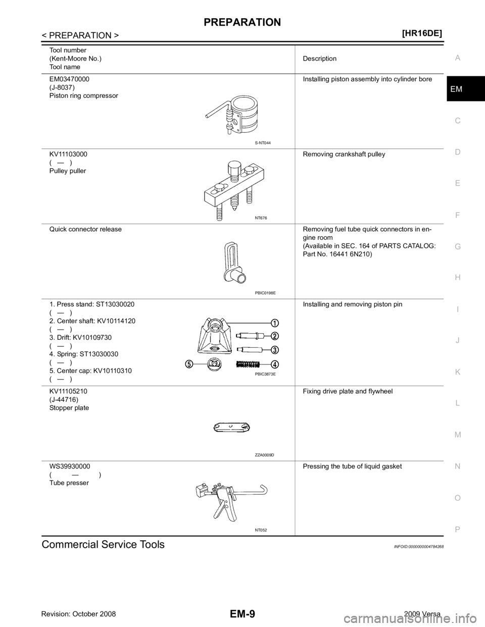
Commercial Service Tools INFOID:0000000004784268
EM03470000
(J-8037)
Piston ring compressor Installing piston assembly into cylinder bore
KV11103000
( — )
Pulley puller Removing crankshaft pulley
Quick connector release Removing fuel tube quick connectors in en- gine room
(Available in SEC. 164 of PARTS CATALOG:
Part No. 16441 6N210)
1. Press stand: ST13030020
( — )
2. Center shaft: KV10114120
( — )
3. Drift: KV10109730
( — )
4. Spring: ST13030030
( — )
5. Center cap: KV10110310
( — ) Installing and removing piston pin
KV11105210
(J-44716)
Stopper plate Fixing drive plate and flywheel
WS39930000
( — )
Tube presser Pressing the tube of liquid gasket
Tool number
(Kent-Moore No.)
Tool name Description PBIC0198E
PBIC3873E
ZZA0009D
NT052
Page 2962 of 4331
![NISSAN TIIDA 2009 Service Repair Manual DRIVE BELTS
EM-15
< ON-VEHICLE MAINTENANCE >
[HR16DE] C
D E
F
G H
I
J
K L
M A EM
NP
O
• When the lock nut is loosened excessively, the idle
r pulley tilts and the correct tension adju NISSAN TIIDA 2009 Service Repair Manual DRIVE BELTS
EM-15
< ON-VEHICLE MAINTENANCE >
[HR16DE] C
D E
F
G H
I
J
K L
M A EM
NP
O
• When the lock nut is loosened excessively, the idle
r pulley tilts and the correct tension adju](/manual-img/5/57398/w960_57398-2961.png)
DRIVE BELTS
EM-15
< ON-VEHICLE MAINTENANCE >
[HR16DE] C
D E
F
G H
I
J
K L
M A EM
NP
O
• When the lock nut is loosened excessively, the idle
r pulley tilts and the correct tension adjust-
ment cannot be performed. Never loo sen it excessively (more than 45 degrees).
• Put a matching mark on the lock nut, and check turning angle with a protractor. Never visually
check the tightening angle.
2. Adjust the belt tension by turning the adjusting bolt. CAUTION:
• When checking immediately after in stallation, first adjust it to the specified value. Then, after
turning crankshaft two turns or more, re-adjust to the specified value to avoid variation in deflec-
tion between pulleys.
• When the tension adjustment is performed, the lo ck nut should be in the condition at step“2”. If
the tension adjustment is performed when the lo ck nut is loosened more than the standard, the
idler pulley tilts and the correct tens ion adjustment cannot be performed.
3. Tighten the idler pulley lock nut.
Removal and Installation INFOID:0000000004784271
REMOVAL 1. Loosen the idler pulley lock nut (A), and then adjust the belt ten- sion by turning the adjusting bolt (B).
2. Remove drive belt.
INSTALLATION 1. Pull the idler pulley in the loosening direction, and then tempo- rarily tighten the idler pulley lock nut (A) to the following torque.
NOTE:
Do not move the lock nut from the tightened position. Proceed to step “2”.
2. Install the drive belt to each pulley. CAUTION:
• Make sure that there is no oil, grease, or coolant, etc. in pulley grooves.
• Make sure that the belt is securely inside the groove on each pulley.
3. Adjust drive belt tension by turning the adjusting bolt. Refer to EM-14, " Tension Adjustment " .
CAUTION: Idler pulley lock nut : 34.8 N·m (3.5 kg-m, 26 ft-lb)
1 : Generator
2 : Water pump
3 : Crankshaft pulley
4 : A/C compressor (with A/C models)
: Idler pulley (without A/C models)
5 : Idler pulley
6 : Drive belt PBIC3643E
1 : Generator
2 : Water pump
3 : Crankshaft pulley
4 : A/C compressor (with A/C models)
: Idler pulley (without A/C models)
5 : Idler pulley
6 : Drive belt
B : Adjusting bolt
Idler pulley lock nut : 4.4 N·m (0.45 kg-m, 39 in-lb)
(temporary tightening) PBIC3643E
Page 3036 of 4331

EM
NP
O
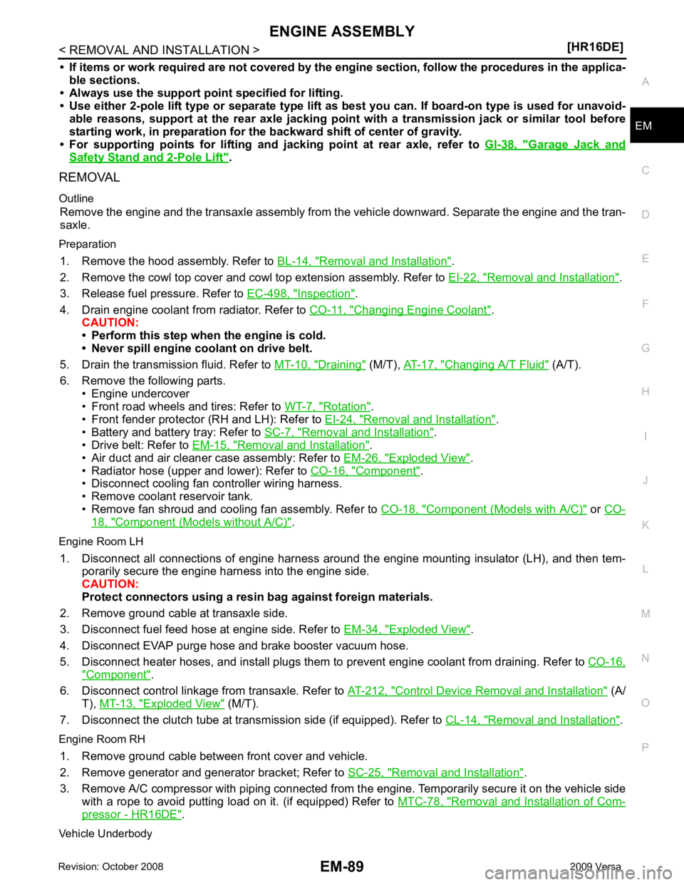
• If items or work required are not covered by the
engine section, follow the procedures in the applica-
ble sections.
• Always use the support poin t specified for lifting.
• Use either 2-pole lift type or separate type lift as best you can. If board-on type is used for unavoid-
able reasons, support at the rear axle jacking point with a transmission jack or similar tool before
starting work, in prepar ation for the backward shif t of center of gravity.
• For supporting points fo r lifting and jacking point at rear axle, refer to GI-38, " Garage Jack and
Safety Stand and 2-Pole Lift " .
REMOVAL
Outline Remove the engine and the transaxle assembly from t he vehicle downward. Separate the engine and the tran-
saxle.
Preparation 1. Remove the hood assembly. Refer to BL-14, " Removal and Installation " .
2. Remove the cowl top cover and cowl top extension assembly. Refer to EI-22, " Removal and Installation " .
3. Release fuel pressure. Refer to EC-498, " Inspection " .
4. Drain engine coolant from radiator. Refer to CO-11, " Changing Engine Coolant " .
CAUTION:
• Perform this step when the engine is cold.
• Never spill engine coolant on drive belt.
5. Drain the transmission fluid. Refer to MT-10, " Draining " (M/T),
AT-17, " Changing A/T Fluid " (A/T).
6. Remove the following parts. • Engine undercover
• Front road wheels and tires: Refer to WT-7, " Rotation " .
• Front fender protector (RH and LH): Refer to EI-24, " Removal and Installation " .
• Battery and battery tray: Refer to SC-7, " Removal and Installation " .
• Drive belt: Refer to EM-15, " Removal and Installation " .
• Air duct and air cleaner case assembly: Refer to EM-26, " Exploded View " .
• Radiator hose (upper and lower): Refer to CO-16, " Component " .
• Disconnect cooling fan controller wiring harness.
• Remove coolant reservoir tank.
• Remove fan shroud and cooling fan assembly. Refer to CO-18, " Component (Models with A/C) " or
CO- 18, " Component (Models without A/C) " .
Engine Room LH 1. Disconnect all connections of engine harness around the engine mounting insulator (LH), and then tem- porarily secure the engine harness into the engine side.
CAUTION:
Protect connectors using a resin bag against foreign materials.
2. Remove ground cable at transaxle side.
3. Disconnect fuel feed hose at engine side. Refer to EM-34, " Exploded View " .
4. Disconnect EVAP purge hose and brake booster vacuum hose.
5. Disconnect heater hoses, and install plugs them to prevent engine coolant from draining. Refer to CO-16," Component " .
6. Disconnect control linkage from transaxle. Refer to AT-212, " Control Device Removal and Installation " (A/
T), MT-13, " Exploded View " (M/T).
7. Disconnect the clutch tube at tr ansmission side (if equipped). Refer to CL-14, " Removal and Installation " .
Engine Room RH 1. Remove ground cable between front cover and vehicle.
2. Remove generator and generator bracket; Refer to SC-25, " Removal and Installation " .
3. Remove A/C compressor with piping connected from t he engine. Temporarily secure it on the vehicle side
with a rope to avoid putting load on it. (if equipped) Refer to MTC-78, " Removal and Installation of Com-
pressor - HR16DE " .
Vehicle Underbody
Page 3077 of 4331
![NISSAN TIIDA 2009 Service Repair Manual EM-130< SERVICE INFORMATION >
[MR18DE]
PREPARATION
PREPARATION
Special Service Tool INFOID:0000000004307119
The actual shapes of Kent-Moore tool s may differ from those of special service tools illust NISSAN TIIDA 2009 Service Repair Manual EM-130< SERVICE INFORMATION >
[MR18DE]
PREPARATION
PREPARATION
Special Service Tool INFOID:0000000004307119
The actual shapes of Kent-Moore tool s may differ from those of special service tools illust](/manual-img/5/57398/w960_57398-3076.png)
EM-130< SERVICE INFORMATION >
[MR18DE]
PREPARATION
PREPARATION
Special Service Tool INFOID:0000000004307119
The actual shapes of Kent-Moore tool s may differ from those of special service tools illustrated here.
Tool number
(Kent-Moore No.)
Tool name Description
KV10111100
(J-37228)
Seal cutter Removing steel oil pan and rear timing
chain case
KV10112100
(BT-8653-A)
Angle wrench Tightening bolts for bearing cap, cylinder
head, etc.
KV10107902
(J-38959)
Valve oil seal puller Removing valve oil seal
EM03470000
(J-8037)
Piston ring compressor Installing piston assembly into cylinder
bore
KV101092S0
(J-26336-B)
Valve spring compressor
1. KV10109210
(J-26336-B and J-26336-20)
Compressor
2. KV10109220
( — )
Adapter (M10)
3. KV10109230
( — )
Adapter (M8) Disassembling and assembling valve
mechanism
WS39930000
( — )
Tube presser Pressing the tube of liquid gasketNT046
NT014
S-NT011
NT044
NT718
NT052
Page 3082 of 4331

EM
NP
O
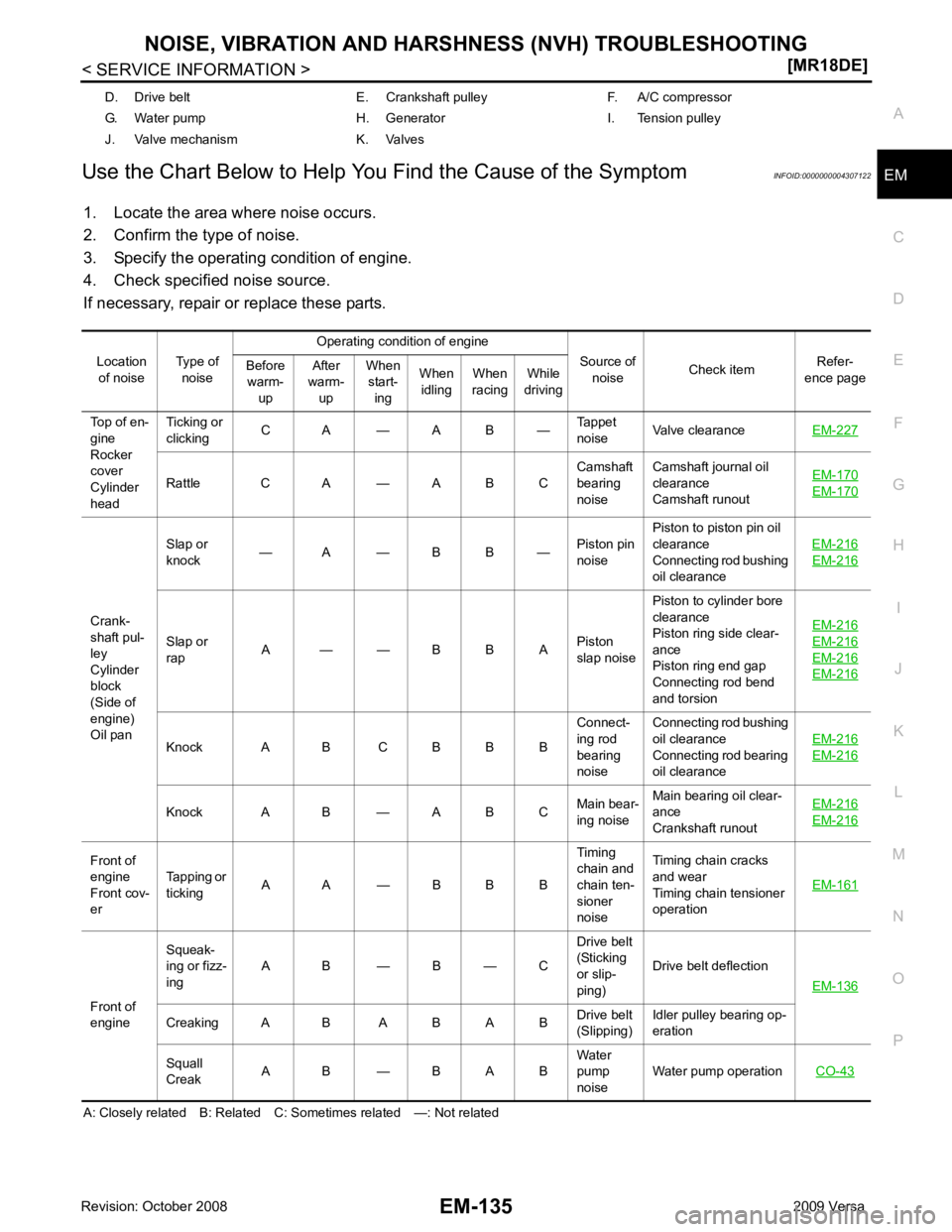
Use the Chart Below to Help You
Find the Cause of the Symptom INFOID:0000000004307122
1. Locate the area where noise occurs.
2. Confirm the type of noise.
3. Specify the operating condition of engine.
4. Check specified noise source.
If necessary, repair or replace these parts.
A: Closely related B: Related C: Sometimes related —: Not related D. Drive belt E. Crankshaft pulley F. A/C compressor
G. Water pump H. Generator I. Tension pulley
J. Valve mechanism K. Valves
Location of noise Type of
noise Operating condition of engine
Source of noise Check item
Refer-
ence page
Before
warm-
up After
warm-
up When
start-
ing When
idling When
racing While
driving
Top of en-
gine
Rocker
cover
Cylinder
head Ticking or
clicking C A — A B —
Tappet
noise Valve clearance
EM-227 Rattle C A — A B C
Camshaft
bearing
noise Camshaft journal oil
clearance
Camshaft runout EM-170 EM-170
Crank-
shaft pul-
ley
Cylinder
block
(Side of
engine)
Oil pan Slap or
knock — A — B B —
Piston pin
noise Piston to piston pin oil
clearance
Connecting rod bushing
oil clearance EM-216 EM-216
Slap or
rap A — — B B A
Piston
slap noise Piston to cylinder bore
clearance
Piston ring side clear-
ance
Piston ring end gap
Connecting rod bend
and torsion EM-216 EM-216
EM-216
EM-216
Knock A B C B B B
Connect-
ing rod
bearing
noise Connecting rod bushing
oil clearance
Connecting rod bearing
oil clearance EM-216 EM-216
Knock A B — A B C
Main bear-
ing noise Main bearing oil clear-
ance
Crankshaft runout EM-216 EM-216
Front of
engine
Front cov-
er Tapping or
ticking A A — B B B Timing
chain and
chain ten-
sioner
noise Timing chain cracks
and wear
Timing chain tensioner
operation EM-161Front of
engine Squeak-
ing or fizz-
ing A B — B — C Drive belt
(Sticking
or slip-
ping) Drive belt deflection
EM-136 Creaking A B A B A B
Drive belt
(Slipping) Idler pulley bearing op-
eration
Squall
Creak A B — B A B Water
pump
noise Water pump operation
CO-43