2009 NISSAN TIIDA keyless entry
[x] Cancel search: keyless entryPage 698 of 4331
BL
N
O P
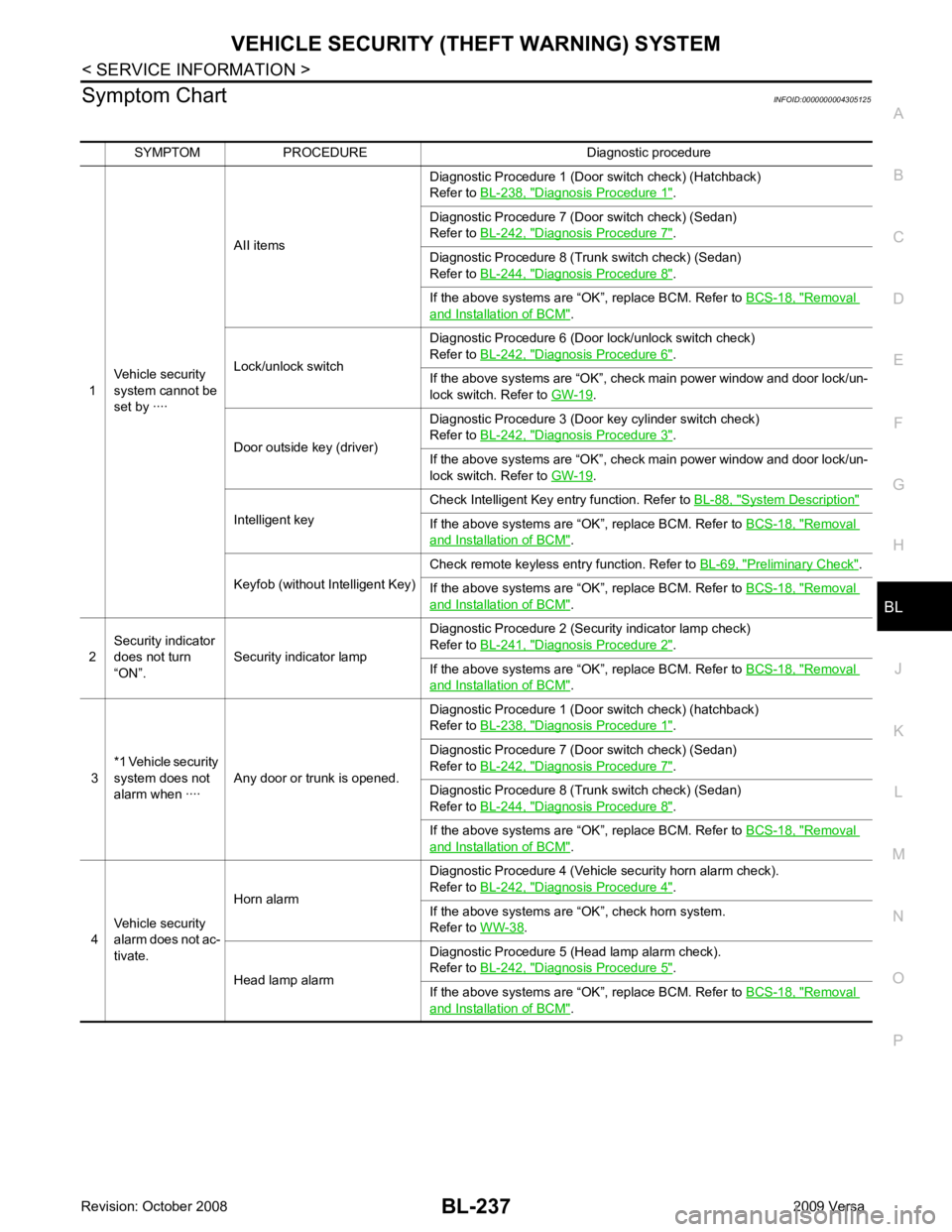
Symptom Chart
INFOID:0000000004305125
SYMPTOM PROCEDURE Diagnostic procedure
1 Vehicle security
system cannot be
set by ···· AII items
Diagnostic Procedure 1 (Door switch check) (Hatchback)
Refer to BL-238, " Diagnosis Procedure 1 " .
Diagnostic Procedure 7 (Door switch check) (Sedan)
Refer to BL-242, " Diagnosis Procedure 7 " .
Diagnostic Procedure 8 (Trunk switch check) (Sedan)
Refer to BL-244, " Diagnosis Procedure 8 " .
If the above systems are “OK”, replace BCM. Refer to BCS-18, " Removal
and Installation of BCM " .
Lock/unlock switch Diagnostic Procedure 6 (Door lock/unlock switch check)
Refer to BL-242, " Diagnosis Procedure 6 " .
If the above systems are “OK”, check main power window and door lock/un-
lock switch. Refer to GW-19 .
Door outside key (driver) Diagnostic Procedure 3 (Door key cylinder switch check)
Refer to BL-242, " Diagnosis Procedure 3 " .
If the above systems are “OK”, check main power window and door lock/un-
lock switch. Refer to GW-19 .
Intelligent key Check Intelligent Key entry function. Refer to
BL-88, " System Description "
If the above systems are “OK”, replace BCM. Refer to
BCS-18, " Removal
and Installation of BCM " .
Keyfob (without Intelligent Key) Check remote keyless entry function. Refer to
BL-69, " Preliminary Check " .
If the above systems are “OK”, replace BCM. Refer to BCS-18, " Removal
and Installation of BCM " .
2 Security indicator
does not turn
“ON”. Security indicator lamp Diagnostic Procedure 2 (Security indicator lamp check)
Refer to BL-241, " Diagnosis Procedure 2 " .
If the above systems are “OK”, replace BCM. Refer to BCS-18, " Removal
and Installation of BCM " .
3 *1 Vehicle security
system does not
alarm when ···· Any door or trunk is opened. Diagnostic Procedure 1 (Door switch check) (hatchback)
Refer to BL-238, " Diagnosis Procedure 1 " .
Diagnostic Procedure 7 (Door switch check) (Sedan)
Refer to BL-242, " Diagnosis Procedure 7 " .
Diagnostic Procedure 8 (Trunk switch check) (Sedan)
Refer to BL-244, " Diagnosis Procedure 8 " .
If the above systems are “OK”, replace BCM. Refer to BCS-18, " Removal
and Installation of BCM " .
4 Vehicle security
alarm does not ac-
tivate. Horn alarm
Diagnostic Procedure 4 (Vehicle security horn alarm check).
Refer to BL-242, " Diagnosis Procedure 4 " .
If the above systems are “OK”, check horn system.
Refer to WW-38 .
Head lamp alarm Diagnostic Procedure 5 (Head lamp alarm check).
Refer to BL-242, " Diagnosis Procedure 5 " .
If the above systems are “OK”, replace BCM. Refer to BCS-18, " Removal
and Installation of BCM " .
Page 699 of 4331
BL-238< SERVICE INFORMATION >
VEHICLE SECURITY (T
HEFT WARNING) SYSTEM
*1 : Make sure the system is in the armed phase.
Diagnosis Procedure 1 INFOID:0000000004305126
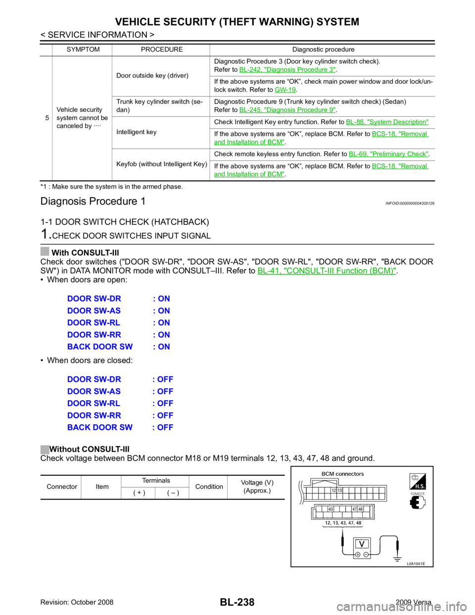
1-1 DOOR SWITCH CHECK (HATCHBACK) 1.
CHECK DOOR SWITCHES INPUT SIGNAL
With CONSULT-III
Check door switches ("DOOR SW-DR", "DOOR SW-AS", "DOOR SW-RL", "DOOR SW-RR", "BACK DOOR
SW") in DATA MONITOR mode with CONSULT–III. Refer to BL-41, " CONSULT-III Function (BCM) " .
• When doors are open:
• When doors are closed:
Without CONSULT-III
Check voltage between BCM connector M18 or M19 terminals 12, 13, 43, 47, 48 and ground.
5
Vehicle security
system cannot be
canceled by ···· Door outside key (driver)
Diagnostic Procedure 3 (Door key cylinder switch check).
Refer to BL-242, " Diagnosis Procedure 3 " .
If the above systems are “OK”, check main power window and door lock/un-
lock switch. Refer to GW-19 .
Trunk key cylinder switch (se-
dan) Diagnostic Procedure 9 (Trunk key cylinder switch check) (Sedan)
Refer to BL-245, " Diagnosis Procedure 9 " .
Intelligent key Check Intelligent Key entry function. Refer to
BL-88, " System Description "
If the above systems are “OK”, replace BCM. Refer to
BCS-18, " Removal
and Installation of BCM " .
Keyfob (without Intelligent Key) Check remote keyless entry function. Refer to
BL-69, " Preliminary Check " .
If the above systems are “OK”, replace BCM. Refer to BCS-18, " Removal
and Installation of BCM " .
SYMPTOM PROCEDURE Diagnostic procedure DOOR SW-DR : ON
DOOR SW-AS : ON
DOOR SW-RL : ON
DOOR SW-RR : ON
BACK DOOR SW : ON
DOOR SW-DR : OFF
DOOR SW-AS : OFF
DOOR SW-RL : OFF
DOOR SW-RR : OFF
BACK DOOR SW : OFF Connector Item
Terminals
ConditionVoltage (V)
(Approx.)
( + ) ( – ) LIIA1041E
Page 714 of 4331
NATS (NISSAN ANTI-THEFT SYSTEM)
BL-253
< SERVICE INFORMATION >
C
D E
F
G H
J
K L
M A
B BL
N
O P
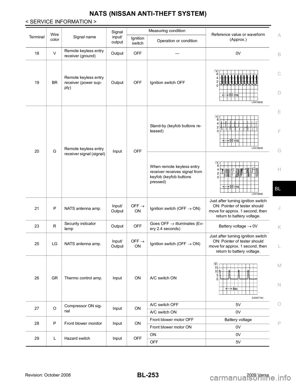
18 V
Remote keyless entry
receiver (ground) Output OFF — 0V
19 BR Remote keyless entry
receiver (power sup-
ply) Output OFF Ignition switch OFF
20 G Remote keyless entry
receiver signal (signal) Input OFFStand-by (keyfob buttons re-
leased)
When remote keyless entry
receiver receives signal from
keyfob (keyfob buttons
pressed)
21 P NATS antenna amp. Input/
Output OFF
→
ON Ignition switch (OFF
→ ON) Just after turning ignition switch
ON: Pointer of tester should
move for approx. 1 second, then return to battery voltage.
23 R Security indicator
lamp Output OFFGoes OFF
→ illuminates (Ev-
ery 2.4 seconds) Battery voltage
→ 0V
25 LG NATS antenna amp. Input/
Output OFF
→
ON Ignition switch (OFF
→ ON) Just after turning ignition switch
ON: Pointer of tester should
move for approx. 1 second, then
return to battery voltage.
26 GR Thermo control amp. Input ON A/C switch ON
27 O Compressor ON sig-
nal Input ONA/C switch OFF 5V
A/C switch ON 0V
28 P Front blower monitor Input ON Front blower motor OFF Battery voltage
Front blower motor ON 0V
29 L Hazard switch Input OFF ON 0V
OFF 5V
Terminal
Wire
color Signal name Signal
input/
output Measuring condition
Reference value or waveform
(Approx.)
Ignition
switch Operation or condition LIIA1893E
LIIA1894E
LIIA1895E
ZJIA0719J
Page 3655 of 4331

LT
N
O P
• to rear combination lamp LH terminal 1
• through grounds B7 and B19.
The BCM also sends a request, via the CAN communication lines, to the combination meter to flash the left
turn signal indicator. The unified meter control unit in the combination meter supplies ground to the left turn
signal indicator lamp and activates the audible turn signal indicator.
With power, ground and input supplied, the BCM controls the flashing of the turn signal lamps.
RH Turn Signal Lamp When turn signal switch is moved to the right turn position, the BCM receives an input signal requesting right
turn signals to flash. The BCM then supplies power
• through BCM terminal 61
• to front combination lamp RH terminal 4 and
• to rear combination lamp RH terminal 6.
Ground is supplied
• to front combination lamp RH terminal 5
• through grounds E15 and E24,
• to rear combination lamp RH terminal 1
• through grounds B117, B132 (all models) and D402 (with hatchback).
The BCM also sends a request, via the CAN communicati on lines, to the combination meter to flash the right
turn signal indicator. The unified meter control unit in the combination meter supplies ground to the right turn
signal indicator lamp and activates the audible turn signal indicator.
With power, ground and input supplied, the BCM controls the flashing of the turn signal lamps.
HAZARD LAMP OPERATION Power is supplied at all times
• through 40A fusible link (letter g , located in fuse, fusible link and relay box)
• to BCM terminal 70,
• through 10A fuse [No. 8, located in fuse block (J/B)]
• to BCM terminal 57,
• through 10A fuse [No. 13, located in fuse block (J/B)]
• to combination meter terminal 27.
Ground is supplied
• to hazard switch terminal 1,
• to BCM terminal 67, and
• to combination meter terminals 21, 22 and 23
• through grounds M57 and M61.
When hazard switch is depressed, ground is supplied
• through hazard switch terminal 2
• to BCM terminal 29.
BCM then supplies power
• to front combination lamp LH terminal 4 and
• to rear combination lamp LH terminal 6
• through BCM terminal 60,
• to front combination lamp RH terminal 4 and
• to rear combination lamp RH terminal 6
• through BCM terminal 61.
Ground is supplied
• to front combination lamp LH and RH terminal 5
• through grounds E15 and E24,
• to rear combination lamp LH terminal 1
• through grounds B7 and B19,
• to rear combination lamp RH terminal 1
• through grounds B117, B132 and D402 (hatchback).
The BCM also supplies input to combination meter ac ross the CAN communication lines. This input is pro-
cessed by unified meter control unit in combination mete r, which in turn supplies ground to the left and right
turn signal indicator lamps.
With power and input supplied, BCM controls flashing of hazard warning lamps.
REMOTE KEYLESS ENTRY SYSTEM OPERATION Power is supplied at all times
• through 40A fusible link (letter g , located in fuse, fusible link and relay box)
• to BCM terminal 70,
Page 4274 of 4331
WT
N
O P
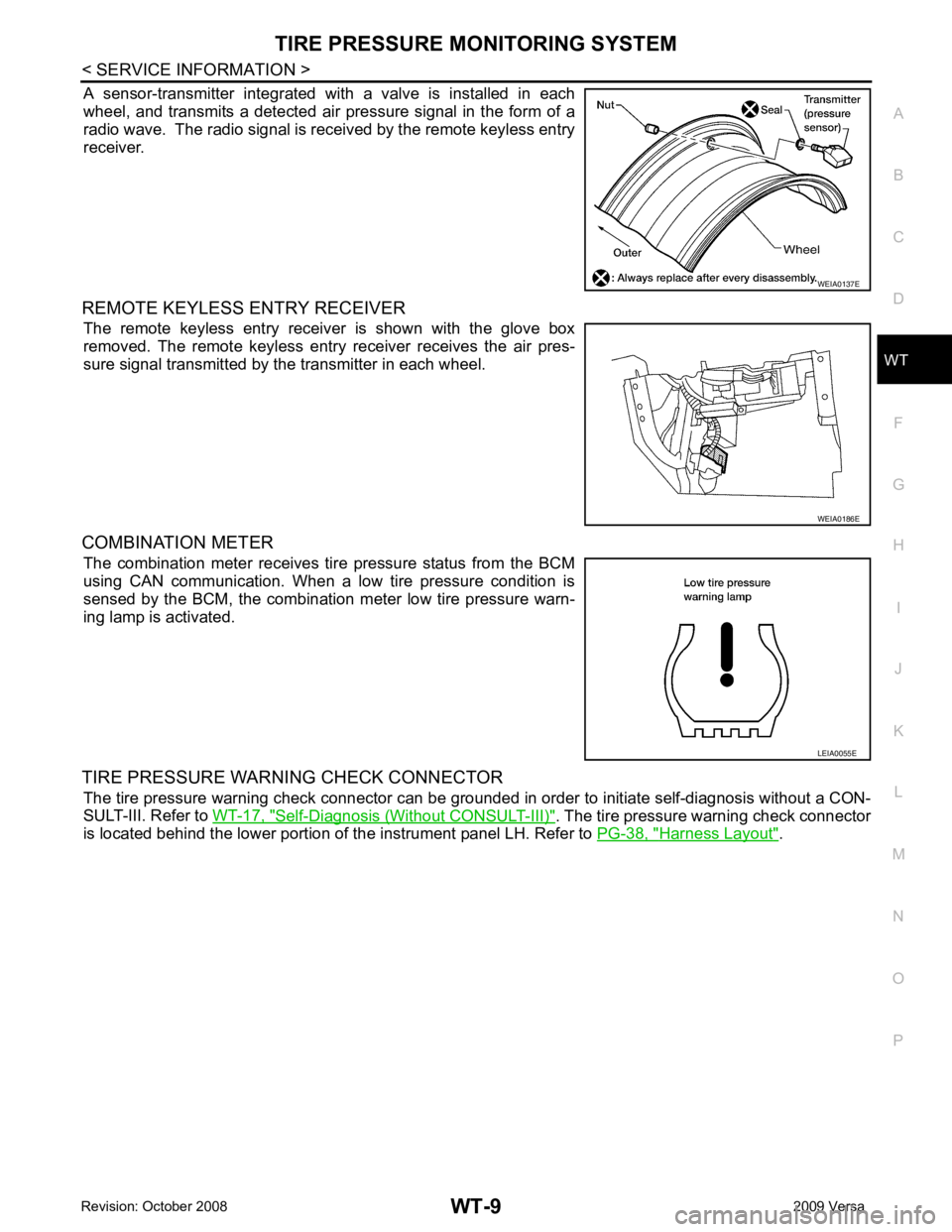
A sensor-transmitter integrated with a valve is installed in each
wheel, and transmits a detected air pressure signal in the form of a
radio wave. The radio signal is received by the remote keyless entry
receiver.
REMOTE KEYLESS ENTRY RECEIVER The remote keyless entry receiver is shown with the glove box
removed. The remote keyless entry receiver receives the air pres-
sure signal transmitted by the transmitter in each wheel.
COMBINATION METER The combination meter receives tire pressure status from the BCM
using CAN communication. When a low tire pressure condition is
sensed by the BCM, the combination meter low tire pressure warn-
ing lamp is activated.
TIRE PRESSURE WARNING CHECK CONNECTOR The tire pressure warning check connector can be grounded in order to initiate self-diagnosis without a CON-
SULT-III. Refer to WT-17, " Self-Diagnosis (Without CONSULT-III) " . The tire pressure warning check connector
is located behind the lower portion of the instrument panel LH. Refer to PG-38, " Harness Layout " . WEIA0186E
LEIA0055E
Page 4283 of 4331
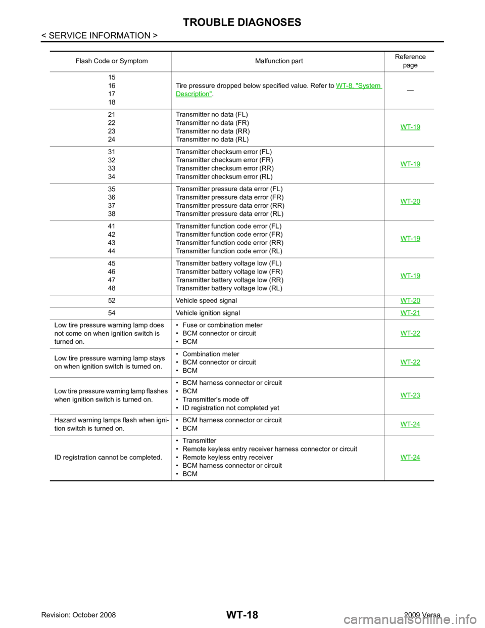
System
Description " .
—
21
22
23
24 Transmitter no data (FL)
Transmitter no data (FR)
Transmitter no data (RR)
Transmitter no data (RL) WT-1931
32
33
34 Transmitter chec
ksum error (FL)
Transmitter chec ksum error (FR)
Transmitter chec ksum error (RR)
Transmitter chec ksum error (RL) WT-1935
36
37
38 Transmitter pressure
data error (FL)
Transmitter pressure data error (FR)
Transmitter pressure data error (RR)
Transmitter pressure data error (RL) WT-2041
42
43
44 Transmitter function
code error (FL)
Transmitter function code error (FR)
Transmitter function code error (RR)
Transmitter function code error (RL) WT-1945
46
47
48 Transmitter battery voltage low (FL)
Transmitter battery voltage low (FR)
Transmitter battery voltage low (RR)
Transmitter battery voltage low (RL) WT-1952 Vehicle speed signal
WT-2054 Vehicle ignition signal
WT-21Low tire pressure warning lamp does
not come on when ignition switch is
turned on. • Fuse or combination meter
• BCM connector or circuit
• BCM WT-22Low tire pressure
warning lamp stays
on when ignition switch is turned on. • Combination meter
• BCM connector or circuit
• BCM WT-22Low tire pressure wa
rning lamp flashes
when ignition switch is turned on. • BCM harness connector or circuit
• BCM
• Transmitter's mode off
• ID registration not completed yet WT-23Hazard warning lamps flash when igni-
tion switch is turned on. • BCM harness connector or circuit
• BCM WT-24ID registration cannot be completed.
• Transmitter
• Remote keyless entry receiver harness connector or circuit
• Remote keyless entry receiver
• BCM harness connector or circuit
• BCM WT-24
Page 4284 of 4331
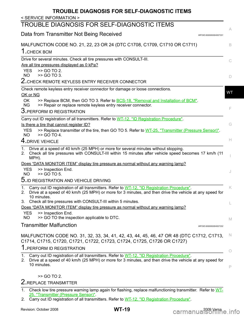
WT
N
O P
TROUBLE DIAGNOSIS FOR
SELF-DIAGNOSTIC ITEMS
Data from Transmitter Not Being Received INFOID:0000000004307331
MALFUNCTION CODE NO. 21, 22 , 23 OR 24 (DTC C1708, C1709, C1710 OR C1711)YES >> GO TO 2.
NO >> GO TO 3. OK >> Replace BCM, then GO TO 3. Refer to
BCS-18, " Removal and Installation of BCM " .
NG >> Repair or replace remote keyless entry receiver connector. ID Registration Procedure " .
Is there a tire that cannot register ID? YES >> Replace transmitter of the
tire, then GO TO 5. Refer to WT-25, " Transmitter (Pressure Sensor) " .
NO >> GO TO 4. “ DATA MONITOR ITEM ” display tire pressure as normal without any warning lamp?
YES >> Inspection End.
NO >> GO TO 5. ID Registration Procedure " .
2. Drive at a speed of 40 km/h (25 MPH) or more fo r 3 minutes, and then drive the vehicle at any speed for
10 minutes.
3. Check all tire pressures with CONSULT-III within 5 minutes.
Does “ DATA MONITOR ITEM ” display tire pressure as normal without any warning lamp?
YES >> Inspection End.
NO >> GO TO the inspection applicable to DTC.
Transmitter Malfunction INFOID:0000000004307332
MALFUNCTION CODE NO. 31, 32, 33 , 34, 41, 42, 43, 44, 45, 46, 47 OR 48 (DTC C1712, C1713,
C1714, C1715, C1720, C1721, C1722, C1723, C1724, C1725, C1726 OR C1727) ID Registration Procedure " .
2. Drive at a speed of 40 km/h (25 MPH) or more fo r 3 minutes, and then drive the vehicle at any speed for
10 minutes.
>> GO TO 2. 25, " Transmitter (Pressure Sensor) " .
2. Carry out ID registration of all transmitters. Refer to WT-12, " ID Registration Procedure " .