2009 NISSAN TIIDA keyless entry
[x] Cancel search: keyless entryPage 553 of 4331
CONSULT-III Application Item " .
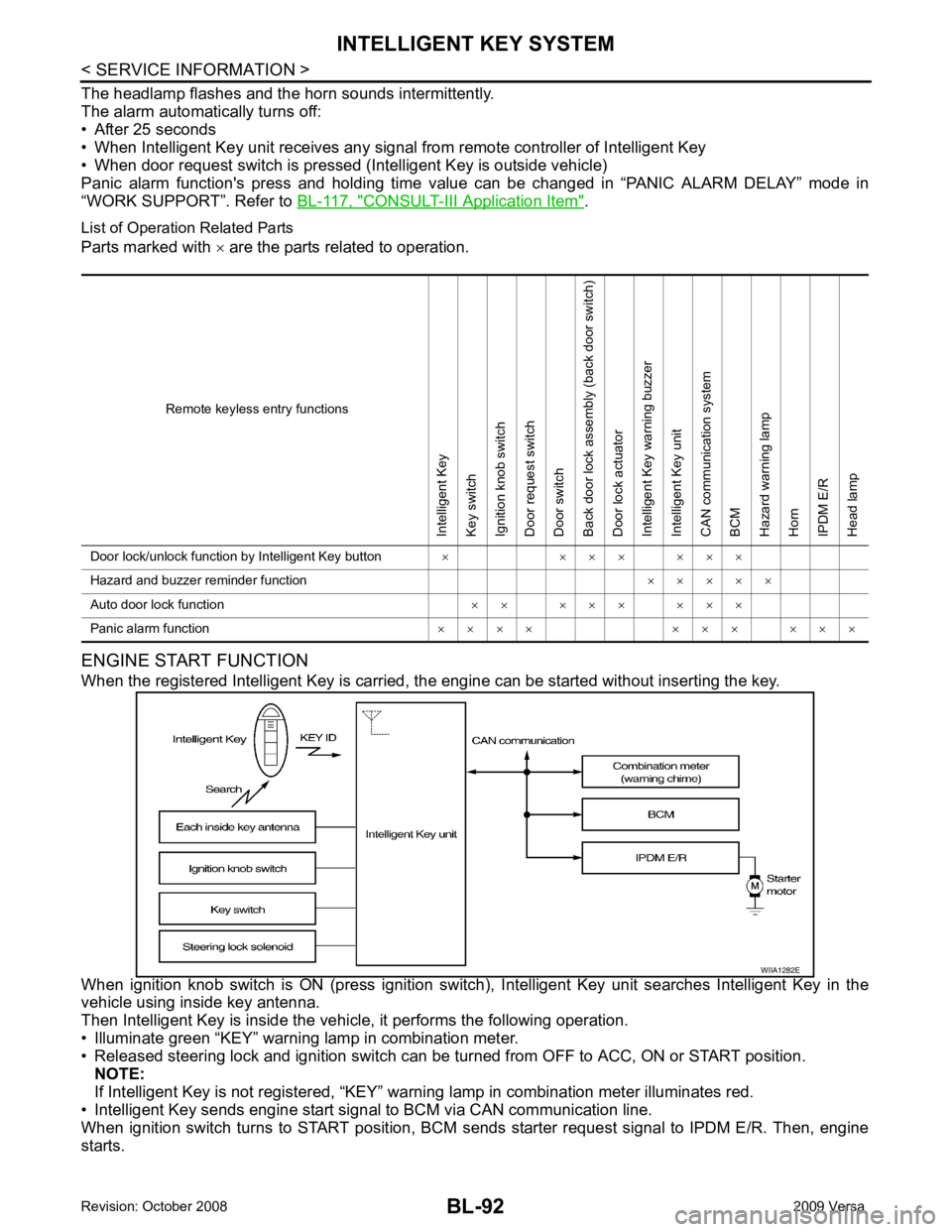
List of Operation Related Parts
Parts marked with × are the parts related to operation.
ENGINE START FUNCTION
When the registered Intelligent Key is carried, the engine can be started without inserting the key.
When ignition knob switch is ON (press ignition switch ), Intelligent Key unit searches Intelligent Key in the
vehicle using inside key antenna.
Then Intelligent Key is inside the vehicle, it performs the following operation.
• Illuminate green “KEY” warning lamp in combination meter.
• Released steering lock and ignition switch can be tu rned from OFF to ACC, ON or START position.
NOTE:
If Intelligent Key is not registered, “KEY” warni ng lamp in combination meter illuminates red.
• Intelligent Key sends engine start signal to BCM via CAN communication line.
When ignition switch turns to START position, BCM s ends starter request signal to IPDM E/R. Then, engine
starts. Remote keyless entry functionsIntelligent Key
Key switch
Ignition knob switch
Door request switch
Door switch
Back door lock assembly (back door switch)
Door lock actuator
Intelligent Key warning buzzer
Intelligent Key unit
CAN communication system
BCM
Hazard warning lamp
Horn
IPDM E/R
Head lamp
Door lock/unlock function by Intelligent Key button × × × × × × ×
Hazard and buzzer reminder function × × × × ×
Auto door lock function × × × × × × × ×
Panic alarm function × × × × × × × × × ×
Page 573 of 4331
BL-112< SERVICE INFORMATION >
INTELLIGENT KEY SYSTEM
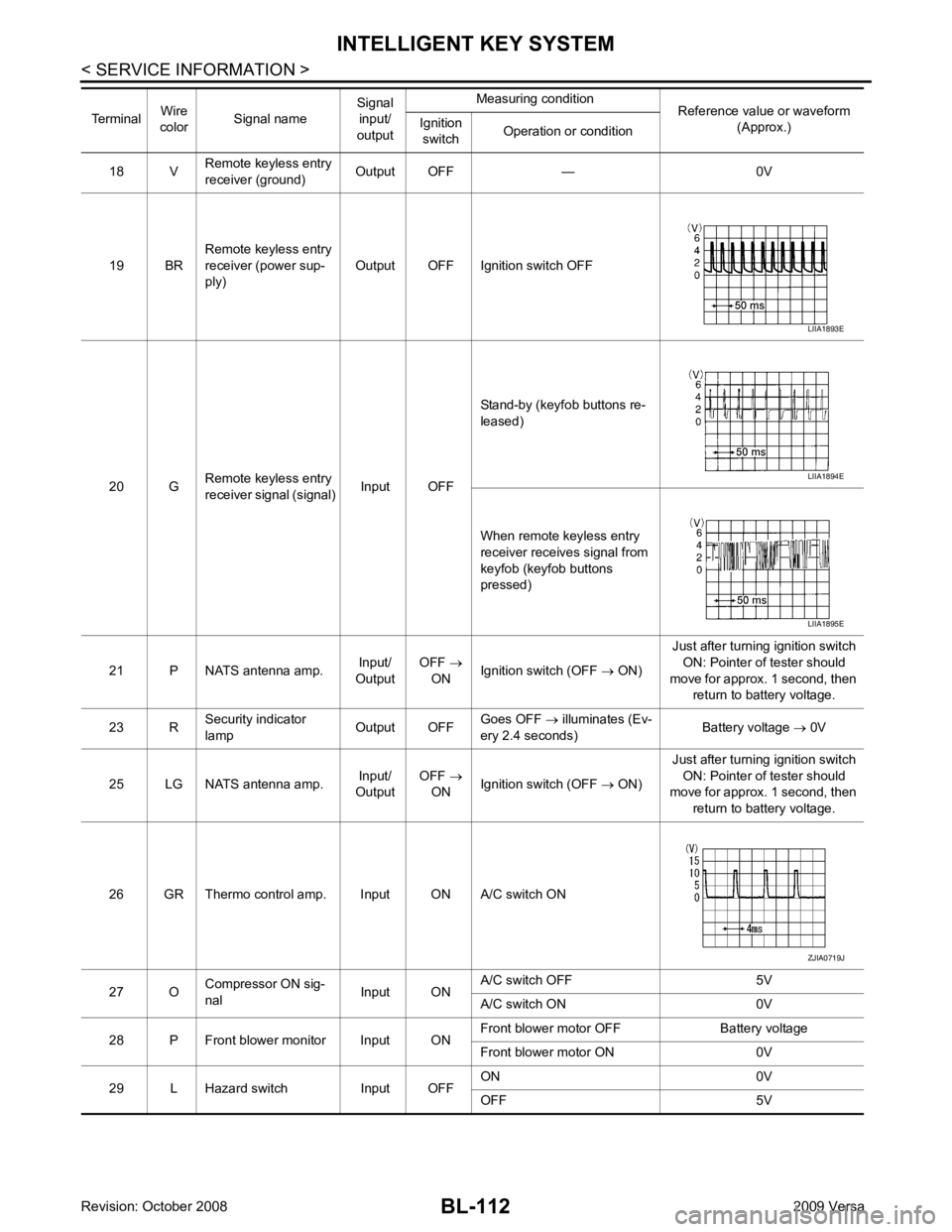
18 V Remote keyless entry
receiver (ground) Output OFF — 0V
19 BR Remote keyless entry
receiver (power sup-
ply) Output OFF Ignition switch OFF
20 G Remote keyless entry
receiver signal (signal) Input OFFStand-by (keyfob buttons re-
leased)
When remote keyless entry
receiver receives signal from
keyfob (keyfob buttons
pressed)
21 P NATS antenna amp. Input/
Output OFF
→
ON Ignition switch (OFF
→ ON) Just after turning ignition switch
ON: Pointer of tester should
move for approx. 1 second, then return to battery voltage.
23 R Security indicator
lamp Output OFFGoes OFF
→ illuminates (Ev-
ery 2.4 seconds) Battery voltage
→ 0V
25 LG NATS antenna amp. Input/
Output OFF
→
ON Ignition switch (OFF
→ ON) Just after turning ignition switch
ON: Pointer of tester should
move for approx. 1 second, then
return to battery voltage.
26 GR Thermo control amp. Input ON A/C switch ON
27 O Compressor ON sig-
nal Input ONA/C switch OFF 5V
A/C switch ON 0V
28 P Front blower monitor Input ON Front blower motor OFF Battery voltage
Front blower motor ON 0V
29 L Hazard switch Input OFF ON 0V
OFF 5V
Terminal
Wire
color Signal name Signal
input/
output Measuring condition
Reference value or waveform
(Approx.)
Ignition
switch Operation or condition LIIA1893E
LIIA1894E
LIIA1895E
ZJIA0719J
Page 583 of 4331

115, " Trouble Diagnosis Procedure " .
• Make sure that vehicle is under the condition shown in “Conditions of vehicle” before starting diagnosis, and
check each symptom.
• If the following “symptoms” are detected, check system s shown in the “Diagnosis/procedure” column in this
order.
Conditions of Vehicle (Operating Conditions)
• “LOCK/UNLOCK BY I-KEY” is ON when setting on CONSULT-III.
• Mechanical key is out of ignition switch.
• Ignition switch is not depressed.
• All doors are closed.
• Intelligent Key is registered.
REMOTE KEYLESS ENTRY FUNCTION MALFUNCTION
Symptom Diagnosis/service procedure Reference page
All function of Intelligent Key system dose not
operate. 1. Check Intelligent Key unit power supply and ground
circuit. BL-126 2. Check Intelligent Key battery inspection.
BL-158 3. Replace Intelligent Key unit.
BL-158Symptom Diagnosis/service procedure Reference page
Door lock/unlock does not operate by all request
switches. 1. Check door switch (hatchback).
BL-131 2. Check door switch (sedan).
BL-134 3. Check key switch.
BL-127 4. Check ignition knob switch.
BL-129 5. Replace Intelligent Key unit.
BL-158Door lock/unlock does not operate by request
switch (driver side). 1. Check door request switch (driver side).
BL-135 2. Check outside key antenna (driver side).
BL-143 3. Replace Intelligent Key unit.
BL-158Door lock/unlock does not operate by request
switch (passenger side). 1. Check door request switch (passenger side).
BL-135 2. Check outside key antenna (passenger side).
BL-143 3. Replace Intelligent Key unit.
BL-158Door lock/unlock does not operate by back door
request switch (hatchback). 1. Check back door request switch.
BL-137 2. Check outside key antenna (rear bumper).
BL-144 3. Replace Intelligent Key unit.
BL-158Door lock/unlock does not operate by trunk
opener request switch (sedan). 1. Check trunk opener request switch.
BL-138 2. Check outside key antenna (rear bumper).
BL-144 3. Replace Intelligent Key unit.
BL-158Auto lock function does not operate.
1. Check “AUTO RELOCK TI
MER” setting in “WORK
SUPPORT”. BL-117 2. Replace Intelligent Key unit.
BL-158Key reminder function does not operate.
1. Check door switch (hatchback).
BL-131 2. Check door switch (sedan).
BL-134 3. Check inside key antenna.
BL-146 4. Check unlock sensor.
BL-140 5. Check Intelligent Key battery.
BL-158 6. Replace Intelligent Key unit.
BL-158
Page 584 of 4331
BL
N
O P
NOTE:
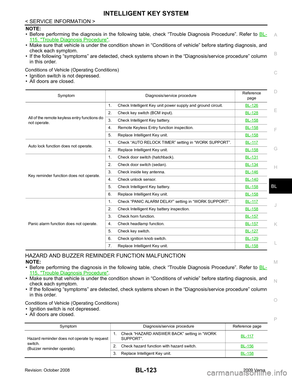
• Before performing the diagnosis in the following table, check “Trouble Diagnosis Procedure”. Refer to BL-115, " Trouble Diagnosis Procedure " .
• Make sure that vehicle is under the condition shown in “Conditions of vehicle” before starting diagnosis, and
check each symptom.
• If the following “symptoms” are detected, check syst ems shown in the “Diagnosis/service procedure” column
in this order.
Conditions of Vehicle (Operating Conditions) • Ignition switch is not depressed.
• All doors are closed.
HAZARD AND BUZZER REMINDER FUNCTION MALFUNCTION NOTE:
• Before performing the diagnosis in the following table, check “Trouble Diagnosis Procedure”. Refer to BL-115, " Trouble Diagnosis Procedure " .
• Make sure that vehicle is under the condition shown in “Conditions of vehicle” before starting diagnosis, and
check each symptom.
• If the following “symptoms” are detected, check syst ems shown in the “Diagnosis/service procedure” column
in this order.
Conditions of Vehicle (Operating Conditions) • Ignition switch is not depressed.
• All doors are closed. Symptom Diagnosis/service procedure
Reference
page
All of the remote keyless entry functions do
not operate. 1. Check Intelligent Key unit power supply and ground circuit.
BL-1262. Check key switch (BCM input).
BL-1283. Check Intelligent Key battery.
BL-1584. Remote Keyless Entry function inspection.
BL-1585. Replace Intelligent Key unit.
BL-158Auto lock function does not operate.
1. Check “AUTO RELOCK TIMER”
setting in “WORK SUPPORT”. BL-117 2. Replace Intelligent Key unit.
BL-158Key reminder function does not operate.
1. Check door switch (hatchback).
BL-1312. Check door switch (sedan).
BL-1343. Check inside key antenna.
BL-1464. Check unlock sensor.
BL-1405. Check Intelligent Key battery.
BL-1586. Replace Intelligent Key unit.
BL-158Panic alarm function does not operate.
1. Check “PANIC ALARM DELAY” setting in “WORK SUPPORT”.
BL-1172. Check Intelligent Key battery inspection.
BL-1583. Check horn function.
BL-1574. Check headlamp function.
BL-1575. Check key switch.
BL-1276. Check ignition knob switch.
BL-1297. Replace Intelligent Key unit.
BL-158Symptom Diagnosis/service procedure Reference page
Hazard reminder does not operate by request
switch.
(Buzzer reminder operate). 1. Check “HAZARD ANSWER BACK” setting in “WORK
SUPPORT”. BL-1172. Check hazard function with hazard switch.
BL-1563. Replace Intelligent Key unit.
BL-158
Page 637 of 4331
BL-176< SERVICE INFORMATION >
BACK DOOR LOCK
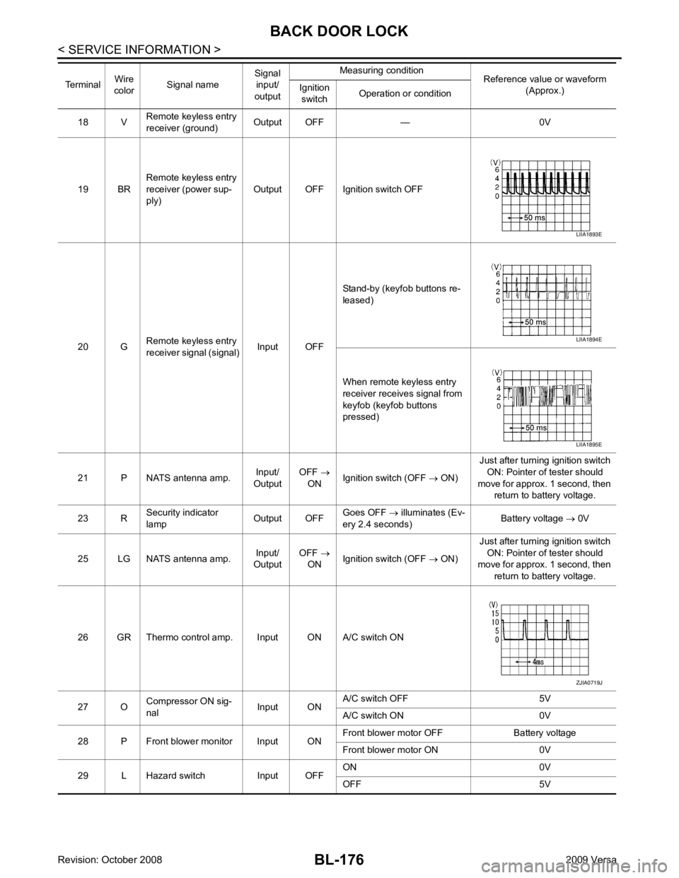
18 V Remote keyless entry
receiver (ground) Output OFF — 0V
19 BR Remote keyless entry
receiver (power sup-
ply) Output OFF Ignition switch OFF
20 G Remote keyless entry
receiver signal (signal) Input OFFStand-by (keyfob buttons re-
leased)
When remote keyless entry
receiver receives signal from
keyfob (keyfob buttons
pressed)
21 P NATS antenna amp. Input/
Output OFF
→
ON Ignition switch (OFF
→ ON) Just after turning ignition switch
ON: Pointer of tester should
move for approx. 1 second, then return to battery voltage.
23 R Security indicator
lamp Output OFFGoes OFF
→ illuminates (Ev-
ery 2.4 seconds) Battery voltage
→ 0V
25 LG NATS antenna amp. Input/
Output OFF
→
ON Ignition switch (OFF
→ ON) Just after turning ignition switch
ON: Pointer of tester should
move for approx. 1 second, then
return to battery voltage.
26 GR Thermo control amp. Input ON A/C switch ON
27 O Compressor ON sig-
nal Input ONA/C switch OFF 5V
A/C switch ON 0V
28 P Front blower monitor Input ON Front blower motor OFF Battery voltage
Front blower motor ON 0V
29 L Hazard switch Input OFF ON 0V
OFF 5V
Terminal
Wire
color Signal name Signal
input/
output Measuring condition
Reference value or waveform
(Approx.)
Ignition
switch Operation or condition LIIA1893E
LIIA1894E
LIIA1895E
ZJIA0719J
Page 661 of 4331
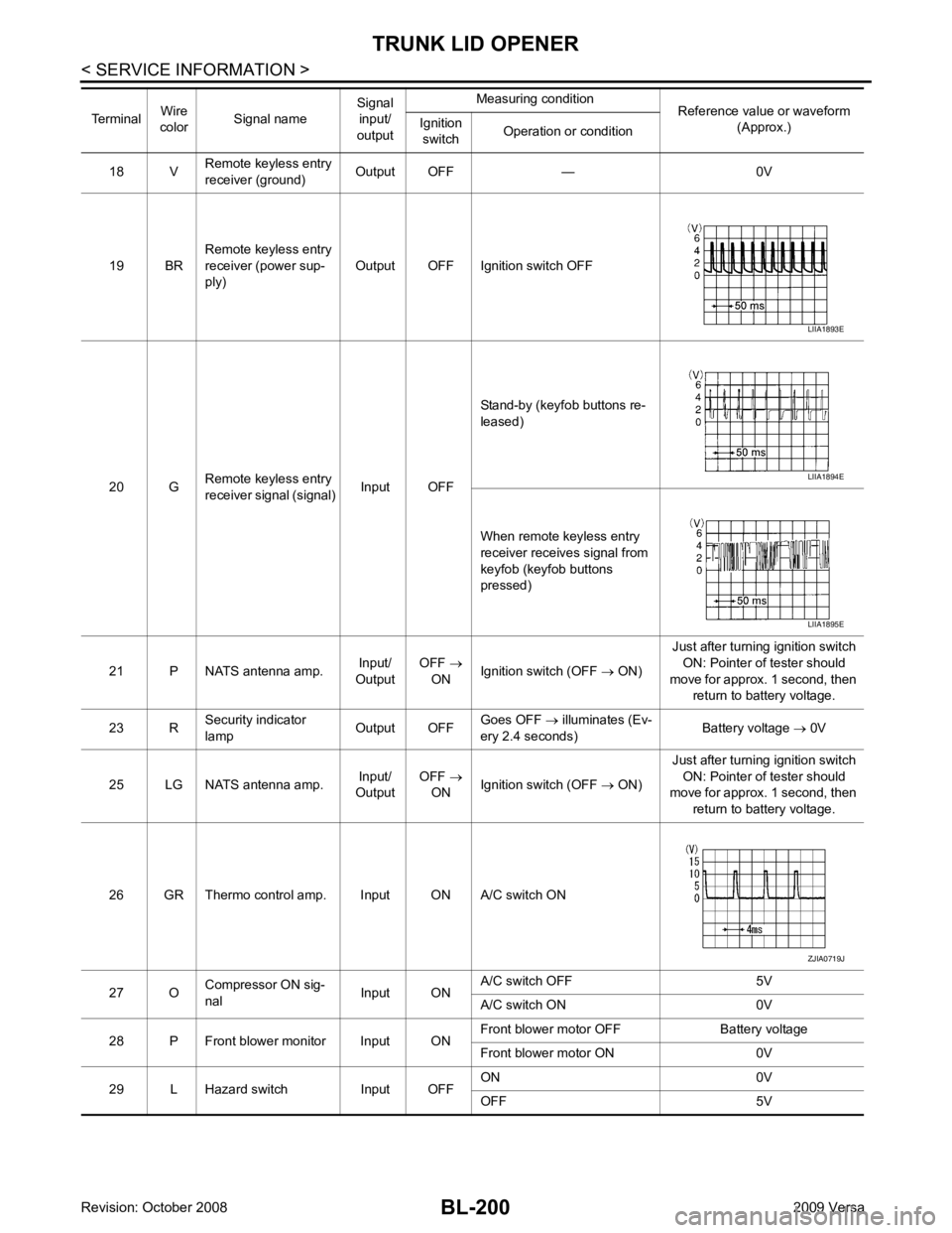
BL-200< SERVICE INFORMATION >
TRUNK LID OPENER
18 V Remote keyless entry
receiver (ground) Output OFF — 0V
19 BR Remote keyless entry
receiver (power sup-
ply) Output OFF Ignition switch OFF
20 G Remote keyless entry
receiver signal (signal) Input OFFStand-by (keyfob buttons re-
leased)
When remote keyless entry
receiver receives signal from
keyfob (keyfob buttons
pressed)
21 P NATS antenna amp. Input/
Output OFF
→
ON Ignition switch (OFF
→ ON) Just after turning ignition switch
ON: Pointer of tester should
move for approx. 1 second, then return to battery voltage.
23 R Security indicator
lamp Output OFFGoes OFF
→ illuminates (Ev-
ery 2.4 seconds) Battery voltage
→ 0V
25 LG NATS antenna amp. Input/
Output OFF
→
ON Ignition switch (OFF
→ ON) Just after turning ignition switch
ON: Pointer of tester should
move for approx. 1 second, then
return to battery voltage.
26 GR Thermo control amp. Input ON A/C switch ON
27 O Compressor ON sig-
nal Input ONA/C switch OFF 5V
A/C switch ON 0V
28 P Front blower monitor Input ON Front blower motor OFF Battery voltage
Front blower motor ON 0V
29 L Hazard switch Input OFF ON 0V
OFF 5V
Terminal
Wire
color Signal name Signal
input/
output Measuring condition
Reference value or waveform
(Approx.)
Ignition
switch Operation or condition LIIA1893E
LIIA1894E
LIIA1895E
ZJIA0719J
Page 689 of 4331
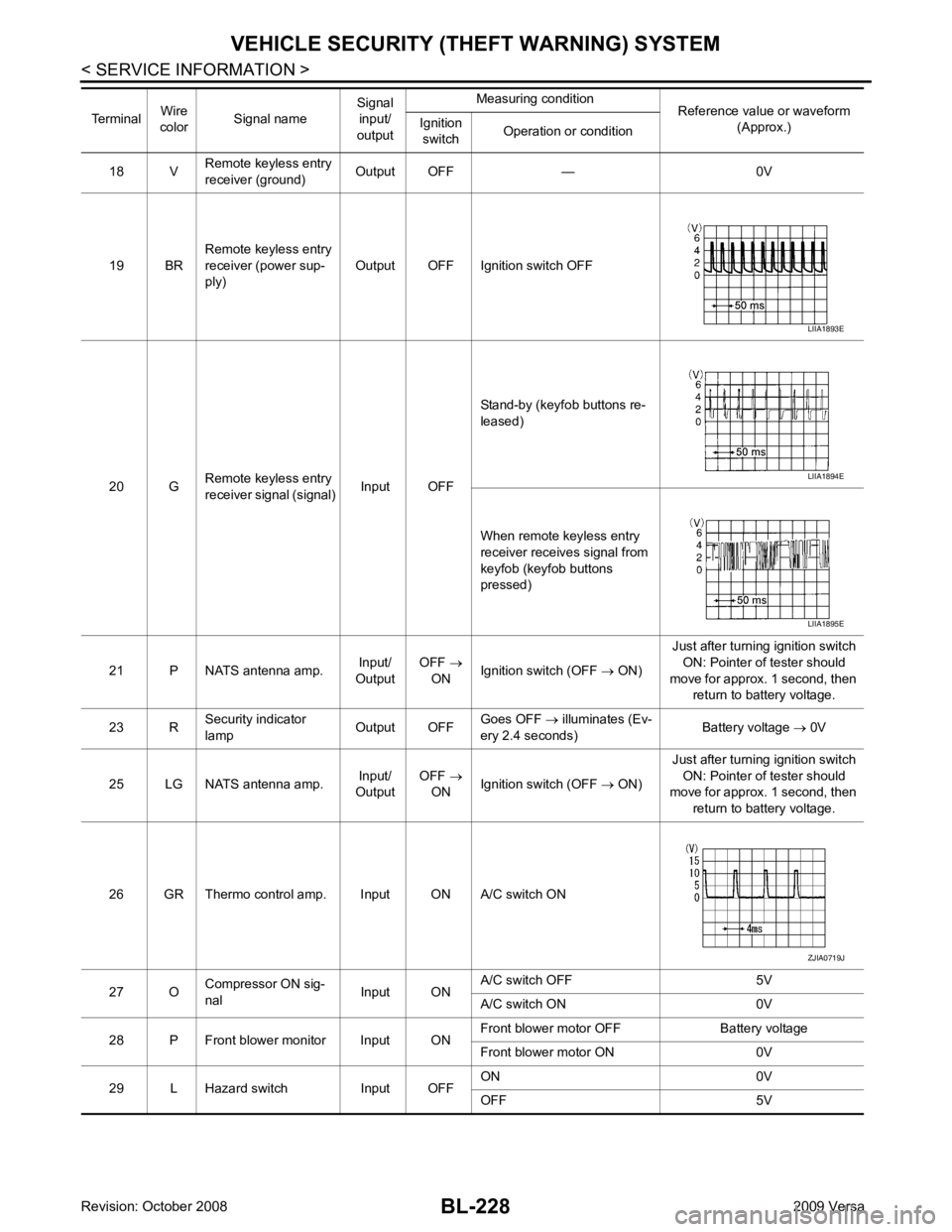
BL-228< SERVICE INFORMATION >
VEHICLE SECURITY (T
HEFT WARNING) SYSTEM
18 V Remote keyless entry
receiver (ground) Output OFF — 0V
19 BR Remote keyless entry
receiver (power sup-
ply) Output OFF Ignition switch OFF
20 G Remote keyless entry
receiver signal (signal) Input OFFStand-by (keyfob buttons re-
leased)
When remote keyless entry
receiver receives signal from
keyfob (keyfob buttons
pressed)
21 P NATS antenna amp. Input/
Output OFF
→
ON Ignition switch (OFF
→ ON) Just after turning ignition switch
ON: Pointer of tester should
move for approx. 1 second, then return to battery voltage.
23 R Security indicator
lamp Output OFFGoes OFF
→ illuminates (Ev-
ery 2.4 seconds) Battery voltage
→ 0V
25 LG NATS antenna amp. Input/
Output OFF
→
ON Ignition switch (OFF
→ ON) Just after turning ignition switch
ON: Pointer of tester should
move for approx. 1 second, then
return to battery voltage.
26 GR Thermo control amp. Input ON A/C switch ON
27 O Compressor ON sig-
nal Input ONA/C switch OFF 5V
A/C switch ON 0V
28 P Front blower monitor Input ON Front blower motor OFF Battery voltage
Front blower motor ON 0V
29 L Hazard switch Input OFF ON 0V
OFF 5V
Terminal
Wire
color Signal name Signal
input/
output Measuring condition
Reference value or waveform
(Approx.)
Ignition
switch Operation or condition LIIA1893E
LIIA1894E
LIIA1895E
ZJIA0719J
Page 696 of 4331
BL
N
O P
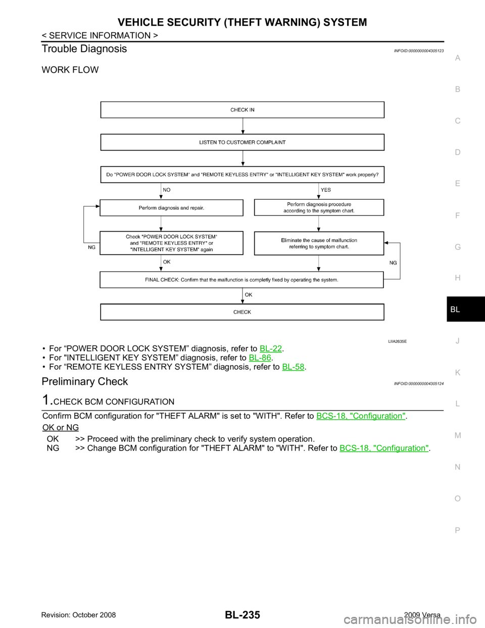
Trouble Diagnosis
INFOID:0000000004305123
WORK FLOW
• For “POWER DOOR LOCK SYSTEM” diagnosis, refer to BL-22 .
• For "INTELLIGENT KEY SYSTEM” diagnosis, refer to BL-86 .
• For “REMOTE KEYLESS ENTRY SYSTEM” diagnosis, refer to BL-58 .
Preliminary Check INFOID:0000000004305124 Configuration " .
OK or NG OK >> Proceed with the preliminary check to verify system operation.
NG >> Change BCM configuration for "THEFT ALARM" to "WITH". Refer to BCS-18, " Configuration " .