2009 NISSAN TIIDA dimensions
[x] Cancel search: dimensionsPage 3169 of 4331
![NISSAN TIIDA 2009 Service Repair Manual EM-222< SERVICE INFORMATION >
[MR18DE]
CYLINDER BLOCK
• Measure the outer diameter of crankshaft main journals with a
micrometer (A).
• If out of the standard, measure the main b NISSAN TIIDA 2009 Service Repair Manual EM-222< SERVICE INFORMATION >
[MR18DE]
CYLINDER BLOCK
• Measure the outer diameter of crankshaft main journals with a
micrometer (A).
• If out of the standard, measure the main b](/manual-img/5/57398/w960_57398-3168.png)
EM-222< SERVICE INFORMATION >
[MR18DE]
CYLINDER BLOCK
• Measure the outer diameter of crankshaft main journals with a
micrometer (A).
• If out of the standard, measure the main bearing oil clearance. Then use undersize bearing. Follow the "MAIN BEARING OIL
CLEARANCE" procedure.
CRANKSHAFT PIN JOURNAL DIAMETER
• Measure the outer diameter of crankshaft pin journal with a micrometer.
• If out of the standard, measure the connecting rod bear ing oil clearance. Then use undersize bearing. Follow
the "CONNECTING ROD BEARIN G OIL CLEARANCE" procedure.
OUT-OF-ROUND AND TAPER OF CRANKSHAFT
• Measure the dimensions at four different points as shown on each main journal and pin journal with a micrometer.
• Out-of-round is indicated by the difference in dimensions between (X) and (Y) at (A) and (B).
• Taper is indicated by the difference in dimension between (A) and
(B) at (X) and (Y).
• If the measured value exceeds the lim it, correct or replace crankshaft.
• If corrected, measure the bearing oil clearance of t he corrected main journal and/or pin journal. Then select
main bearing and/or connecting rod bearing. Follow the "MAIN BEARING OIL CLEARANCE" and/or "CON-
NECTING ROD BEARING OIL CLEARANCE" procedures.
CRANKSHAFT RUNOUT
• Place a V-block on a precise flat table to support the journals on the both end of the crankshaft.
• Place a dial indicator (A) straight up on the No. 3 journal.
• While rotating crankshaft, read t he movement of the pointer on the
dial indicator. (Total indicator reading)
• If it exceeds the limit, replace crankshaft.
CONNECTING ROD BEARING OIL CLEARANCE
Method by Calculation Standard: 51.959 - 51.979 mm (2.0456 - 2.0464 in) dia. PBIC3457J
Standard: 43.953 - 43.971 mm (1.7304-1.7311 in) dia.
Limit: Out-of-round [Difference between (X) and (Y)] : 0.0035 mm (0.0001 in)
Taper [Difference between (A) and (B)] : 0.0035 mm (0.0001 in) PBIC3459J
Standard : 0.05 mm (0.0020 in)
Limit : 0.10 mm (0.0040 in) PBIC3458J
Page 3172 of 4331
![NISSAN TIIDA 2009 Service Repair Manual EM
NP
O
• Measure the outer diameters [(d
1), (d 2)] at two positions as shown.
• If reduction appears in places other than (B) range, regard it as (d 2).
• If it exceeds the limi NISSAN TIIDA 2009 Service Repair Manual EM
NP
O
• Measure the outer diameters [(d
1), (d 2)] at two positions as shown.
• If reduction appears in places other than (B) range, regard it as (d 2).
• If it exceeds the limi](/manual-img/5/57398/w960_57398-3171.png)
EM
NP
O
• Measure the outer diameters [(d
1), (d 2)] at two positions as shown.
• If reduction appears in places other than (B) range, regard it as (d 2).
• If it exceeds the limit (a large difference in dimensions), replace main bearing cap bolt with a new one.
CONNECTING ROD BOLT OUTER DIAMETER • Measure the outer diameter (d) at position as shown.
• If reduction appears in a position other than (d), regard it as (d).
• When (d) exceeds the limit (when it becomes thinner), replace connecting rod bolt with a new one.
CLOGGED OR DAMAGED OIL FILTER (FOR INTAKE VALVE TIMING CONTROL)
• Make sure that there is no foreign material on the oil filter and check it for clogging.
- Clean it if necessary.
• Check the oil filter for damage.
- Replace it if necessary.
FLYWHEEL DEFLECTION (M/T MODELS) • Measure the deflection of flywheel contact surface to clutch with a dial indicator (A).
• Measure the deflection at 210 mm (8.27 in) diameter.
• If measured value is out of the standard, replace flywheel.
• If a trace of burn or discolorati on is found on the surface, repair it
with sandpaper.
CAUTION:
When measuring, keep magnetic fields (such as dial indicator
stand) away from signal plate of the rear end of crankshaft.
MOVEMENT AMOUNT OF FLYWHEEL (M/T MODELS) CAUTION:
Never disassemble double mass flywheel.
Movement Amount of Thrust (Fore-and-Aft) Direction • Measure the movement amount of thrust (fore-and-af t) direction when 100 N (10.2 kg, 22 lb) force is added
at the portion of 125 mm (4.92 in) radi us from the center of flywheel.
A : (d1) measuring position
B : (d2) measuring position
Limit [(d 1) – (d 2)]: 0.15 mm (0.0059 in) PBIC3273J
Page 3175 of 4331
![NISSAN TIIDA 2009 Service Repair Manual EM-228< SERVICE INFORMATION >
[MR18DE]
SERVICE DATA AND SPECIFICATIONS (SDS)
VALVE
Valve Timing Unit: degree
( ): Valve timing control “ON”
Valve Dimensions Unit: mm (in)
Groove of No. 1 journal NISSAN TIIDA 2009 Service Repair Manual EM-228< SERVICE INFORMATION >
[MR18DE]
SERVICE DATA AND SPECIFICATIONS (SDS)
VALVE
Valve Timing Unit: degree
( ): Valve timing control “ON”
Valve Dimensions Unit: mm (in)
Groove of No. 1 journal](/manual-img/5/57398/w960_57398-3174.png)
EM-228< SERVICE INFORMATION >
[MR18DE]
SERVICE DATA AND SPECIFICATIONS (SDS)
VALVE
Valve Timing Unit: degree
( ): Valve timing control “ON”
Valve Dimensions Unit: mm (in)
Groove of No. 1 journal 4.000 - 4.300 (0.1575 - 0.1587) —
Items Standard Limit PBIC0924E
Valve timing a b c d e f
212 224 -8 (32) 52 (12) 7 25 PBIC4542E
Valve head diameter (D) Intake 33.8 - 34.1 (1.331 - 1.343)
Exhaust 27.6 - 27.9 (1.087 - 1.098)
Valve length (L) Intake 106.27 (4.184)
Exhaust 105.26 (4.144)
Valve stem diameter (d) Intake 5.465 - 5.480 (0.2152 - 0.2157)
Exhaust 5.455 - 5.470 (0.2148 - 0.2154)
Valve seat angle ( α 45°15 ′ - 45 °45 ′ SEM188A
Page 3254 of 4331

GI
SECTION GI
N
O P
CONTENTS
GENERAL INFORMATION
SERVICE INFORMATION .. ..........................2
PRECAUTIONS .............................................. .....2
Description .......................................................... ......2
Precaution for Supplemental Restraint System
(SRS) "AIR BAG" and "SEAT BELT PRE-TEN-
SIONER" ............................................................. ......
2
Precaution Necessary fo r Steering Wheel Rota-
tion After Battery Disconnect ............................... ......
2
General Precaution ............................................. ......3
Precaution for Three Way Catalyst ..................... ......4
Precaution for Fuel (Unleaded Regular Gasoline
Recommended) ................................................... ......
4
Precaution for Multiport Fuel Injection System or
Engine Control System ....................................... ......
5
Precaution for Hoses ........................................... ......5
Precaution for Engine Oils .................................. ......6
Precaution for Air Conditioning ........................... ......6
HOW TO USE THIS MANUAL ....................... .....7
Description .......................................................... ......7
Terms .................................................................. ......7
Units .................................................................... ......7
Contents .............................................................. ......7
Relation between Illustrations and Descriptions . ......8
Component .......................................................... ......8
How to Follow Trouble Diagnosis ........................ ......9
How to Read Wiring Diagr am ..................................13
Abbreviations ...................................................... ....20
SERVICE INFORMATION FOR ELECTRICAL
INCIDENT ....................................................... ....
22
How to Check Terminal ...........................................22 How to Perform Efficient Diagnosis for an Electri-
cal Incident .......................................................... ....
25
Control Units and Electrical Parts ........................ ....32
CONSULT-III CHECKING SYSTEM ................. 35
Description ........................................................... ....35
Function and System Application ........................ ....35
CONSULT-III Data Link Connector (DLC) Circuit ....36
LIFTING POINT ................................................. 38
Special Service Tool ............................................ ....38
Garage Jack and Safety Stand and 2-Pole Lift ... ....38
Board-On Lift ....................................................... ....39
TOW TRUCK TOWING ..................................... 40
Tow Truck Towing ............................................... ....40
Vehicle Recovery (Freeing a Stuck Vehicle) ....... ....40
TIGHTENING TORQUE OF STANDARD
BOLTS ............................................................... 41
Tightening Torque Table ..................................... ....41
RECOMMENDED CHEMICAL PRODUCTS
AND SEALANTS ............................................... 42
Recommended Chemical Product and Sealant ... ....42
IDENTIFICATION INFORMATION .................... 43
Model Variation .................................................... ....43
Dimensions .......................................................... ....46
Wheels & Tires .................................................... ....46
TERMINOLOGY ................................................ 47
SAE J1930 Terminology List ............................... ....47
Page 3642 of 4331

LT-36< SERVICE INFORMATION >
HEADLAMP (FOR CANADA) - DAY
TIME LIGHT SYSTEM -
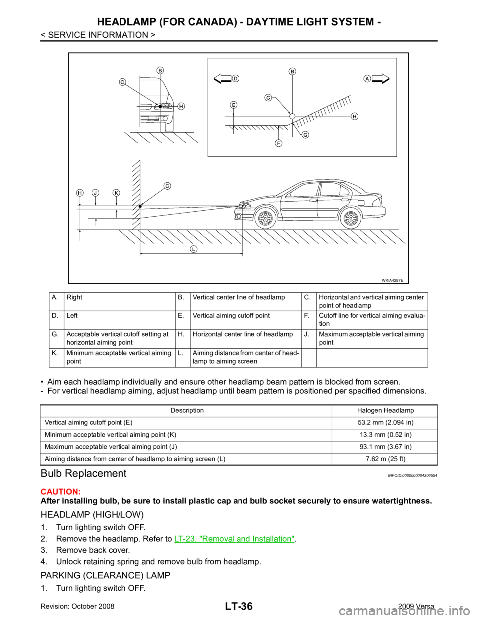
• Aim each headlamp individually and ensure other headlamp beam pattern is blocked from screen.
- For vertical headlamp aiming, adjust headlamp until beam pattern is positioned per specified dimensions.
Bulb Replacement INFOID:0000000004306554
CAUTION:
After installing bulb, be sure to install plastic cap and bulb socket securely to ensure watertightness.
HEADLAMP (HIGH/LOW)
1. Turn lighting switch OFF.
2. Remove the headlamp. Refer to LT-23, " Removal and Installation " .
3. Remove back cover.
4. Unlock retaining spring and remove bulb from headlamp.
PARKING (CLEARANCE) LAMP
1. Turn lighting switch OFF. A. Right B. Vertical center line of headlamp C. Horizontal and vertical aiming center
point of headlamp
D. Left E. Vertical aiming cutoff point F. Cutoff line for vertical aiming evalua- tion
G. Acceptable vertical cutoff setting at horizontal aiming point H. Horizontal center line of headlamp J. Maximum acceptable vertical aiming
point
K. Minimum acceptable vertical aiming point L. Aiming distance from center of head-
lamp to aiming screen WKIA4287E
Description Halogen Headlamp
Vertical aiming cutoff point (E) 53.2 mm (2.094 in)
Minimum acceptable vertical aiming point (K) 13.3 mm (0.52 in)
Maximum acceptable vertical aiming point (J) 93.1 mm (3.67 in)
Aiming distance from center of headlamp to aiming screen (L) 7.62 m (25 ft)
Page 3724 of 4331
![NISSAN TIIDA 2009 Service Repair Manual PRECAUTIONS
LU-3
< PRECAUTION >
[HR16DE] C
D E
F
G H
I
J
K L
M A LU
NP
O
Precaution for Liquid Gasket
INFOID:0000000004784386
REMOVAL OF LIQUID GASKET SEALING • After removing nuts and bolts, separa NISSAN TIIDA 2009 Service Repair Manual PRECAUTIONS
LU-3
< PRECAUTION >
[HR16DE] C
D E
F
G H
I
J
K L
M A LU
NP
O
Precaution for Liquid Gasket
INFOID:0000000004784386
REMOVAL OF LIQUID GASKET SEALING • After removing nuts and bolts, separa](/manual-img/5/57398/w960_57398-3723.png)
PRECAUTIONS
LU-3
< PRECAUTION >
[HR16DE] C
D E
F
G H
I
J
K L
M A LU
NP
O
Precaution for Liquid Gasket
INFOID:0000000004784386
REMOVAL OF LIQUID GASKET SEALING • After removing nuts and bolts, separate the mating surface, using Tool and remove old liquid gasket sealing.
CAUTION:
Be careful not to damage the mating surfaces.
• Tap Tool to insert it (1), and then slide it by tapping on the side (2) as shown.
• In areas where Tool is difficult to use, use plastic hammer to lightly tap the parts, to remove it.
CAUTION:
If for some unavoidable reason suitable tool such as screw-
driver is used, be careful not to damage the mating surfaces.
LIQUID GASKET APPLICATION PROCEDURE 1. Remove old liquid gasket adhering to the liquid gasket applica- tion surface and the mating surface, using scraper.
• Remove liquid gasket completely from the groove of the liquid
gasket application surface, bolts, and bolt holes.
2. Thoroughly clean the mating surfaces and remove adhering moisture, grease and foreign materials.
3. Attach liquid gasket tube to Tool.
Use Genuine RTV Silicone Seal ant or equivalent. Refer to GI-42, " Recommended Chemical Prod-
uct and Sealant " .
4. Apply liquid gasket without breaks to the spec ified location with the specified dimensions.
• If there is a groove for the liquid gasket application, apply liquid gasket to the groove.
• As for the bolt holes, normally apply liquid gasket inside the holes. Occasionally, it should be applied outside the holes.
Make sure to read the text of service manual.
• Within five minutes of liquid gasket application, install the mat- ing component.
• If liquid gasket protrudes, wipe it off immediately.
• Do not retighten nuts or bolts after the installation.
• After 30 minutes or more have passed from the installation, fill engine oil and engine coolant.
CAUTION:
If there are specific instructions in this manual, observe them.
Tool number : KV10111100 (J-37228)
WBIA0566E
Tool number : WS39930000 ( — )
PBIC0003E
WBIA0567E
SEM159F
Page 3733 of 4331
![NISSAN TIIDA 2009 Service Repair Manual LU-12< SERVICE INFORMATION >
[MR18DE]
PRECAUTIONS
Precaution for Liquid Gasket INFOID:0000000004788557
REMOVAL OF LIQUID GASKET SEALING
• After removing nuts and bolts, separate the mating surface, NISSAN TIIDA 2009 Service Repair Manual LU-12< SERVICE INFORMATION >
[MR18DE]
PRECAUTIONS
Precaution for Liquid Gasket INFOID:0000000004788557
REMOVAL OF LIQUID GASKET SEALING
• After removing nuts and bolts, separate the mating surface,](/manual-img/5/57398/w960_57398-3732.png)
LU-12< SERVICE INFORMATION >
[MR18DE]
PRECAUTIONS
Precaution for Liquid Gasket INFOID:0000000004788557
REMOVAL OF LIQUID GASKET SEALING
• After removing nuts and bolts, separate the mating surface, using Tool and remove old liquid gasket sealing.
CAUTION:
Be careful not to damage the mating surfaces.
• Tap Tool to insert it (1), and then slide it by tapping on the side (2) as shown.
• In areas where Tool is difficult to use, use plastic hammer to lightly tap the parts, to remove it.
CAUTION:
If for some unavoidable reason suitable tool such as screw-
driver is used, be careful no t to damage the mating surfaces.
LIQUID GASKET APPLICATION PROCEDURE
1. Remove old liquid gasket adhering to the liquid gasket applica- tion surface and the mating surface, using scraper.
• Remove liquid gasket completely from the groove of the liquid
gasket application surface, bolts, and bolt holes.
2. Thoroughly clean the mating surfaces and remove adhering moisture, grease and foreign materials.
3. Attach liquid gasket tube to Tool.
Use Genuine RTV Silicone Seal ant or equivalent. Refer to GI-42, " Recommended Chemical Prod-
uct and Sealant " .
4. Apply liquid gasket without breaks to the specif ied location with the specified dimensions.
• If there is a groove for the liquid gasket application, apply liquid gasket to the groove.
• As for the bolt holes, normally apply liquid gasket inside the holes. Occasionally, it should be applied outside the holes.
Make sure to read the text of service manual.
• Within five minutes of liquid gasket application, install the mat- ing component.
• If liquid gasket protrudes, wipe it off immediately.
• Do not retighten nuts or bolts after the installation.
• After 30 minutes or more have passed from the installation, fill engine oil and engine coolant.
CAUTION:
If there are specific instructions in this manual, observe them.
Tool number : KV10111100 (J-37228)
WBIA0566E
Tool number : WS39930000 ( — )
PBIC0003E
WBIA0567E
SEM159F
Page 3823 of 4331

MT
N
O P
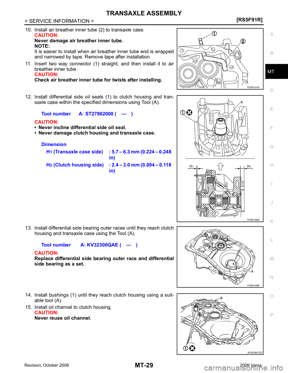
10. Install air breather inner tube (2) to transaxle case.
CAUTION:
Never damage air breather inner tube.
NOTE:
It is easier to install when air breather inner tube end is wrapped
and narrowed by tape. Remove tape after installation.
11. Insert two way connector (1) straight, and then install it to air breather inner tube.
CAUTION:
Check air breather inner tube fo r twists after installing.
12. Install differential side oil seals (1) to clutch housing and tran- saxle case within the specified dimensions using Tool (A).
CAUTION:
• Never incline differential side oil seal.
• Never damage clutch housing and transaxle case.
13. Install differential side bearing outer races until they reach clutch housing and transaxle case using the Tool (A).
CAUTION:
Replace differential side bearing outer race and differential
side bearing as a set.
14. Install bushings (1) until they reach clutch housing using a suit- able tool (A).
15. Install oil channel to clutch housing. CAUTION:
Never reuse oil channel. JPDIC0637ZZ