2009 NISSAN TIIDA dimensions
[x] Cancel search: dimensionsPage 2992 of 4331

EM
NP
O
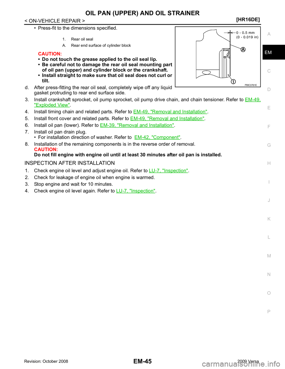
• Press-fit to the dimensions specified.
CAUTION:
• Do not touch the grease applied to the oil seal lip.
• Be careful not to damage the rear oil seal mounting part of oil pan (upper) and cylinder block or the crankshaft.
• Install straight to make sure that oil seal does not curl or tilt.
d. After press-fitting the rear oil seal, completely wipe off any liquid gasket protruding to rear end surface side.
3. Install crankshaft sprocket, oil pump sprocket, oi l pump drive chain, and chain tensioner. Refer to EM-49," Exploded View " .
4. Install timing chain and related parts. Refer to EM-49, " Removal and Installation " .
5. Install front cover and related parts. Refer to EM-49, " Removal and Installation " .
6. Install oil pan (lower). Refer to EM-39, " Removal and Installation " .
7. Install oil pan drain plug. • For installation direction of washer. Refer to EM-42, " Component " .
8. Installation of the remaining components is in the reverse order of removal. CAUTION:
Do not fill engine with engi ne oil until at least 30 minutes after oil pan is installed.
INSPECTION AFTER INSTALLATION 1. Check engine oil level and adjust engine oil. Refer to LU-7, " Inspection " .
2. Check for leakage of engine oil when engine is warmed.
3. Stop engine and wait for 10 minutes.
4. Check engine oil level again. Refer to LU-7, " Inspection " .
1. Rear oil seal
A. Rear end surface of cylinder block
Page 3031 of 4331

Cylinder Head " .
• If dimensions are out of the standard, r eplace valve and check valve seat contact.
Valve Guide Clearance
Valve Stem Diameter
• Measure the diameter of valve stem with micrometer (A).
Valve Guide Inner Diameter
• Measure the inner diameter of valve guide with bore gauge.
Valve Guide Clearance
• (Valve guide clearance) = (Valve guide inner diameter) – (Valve
stem diameter)
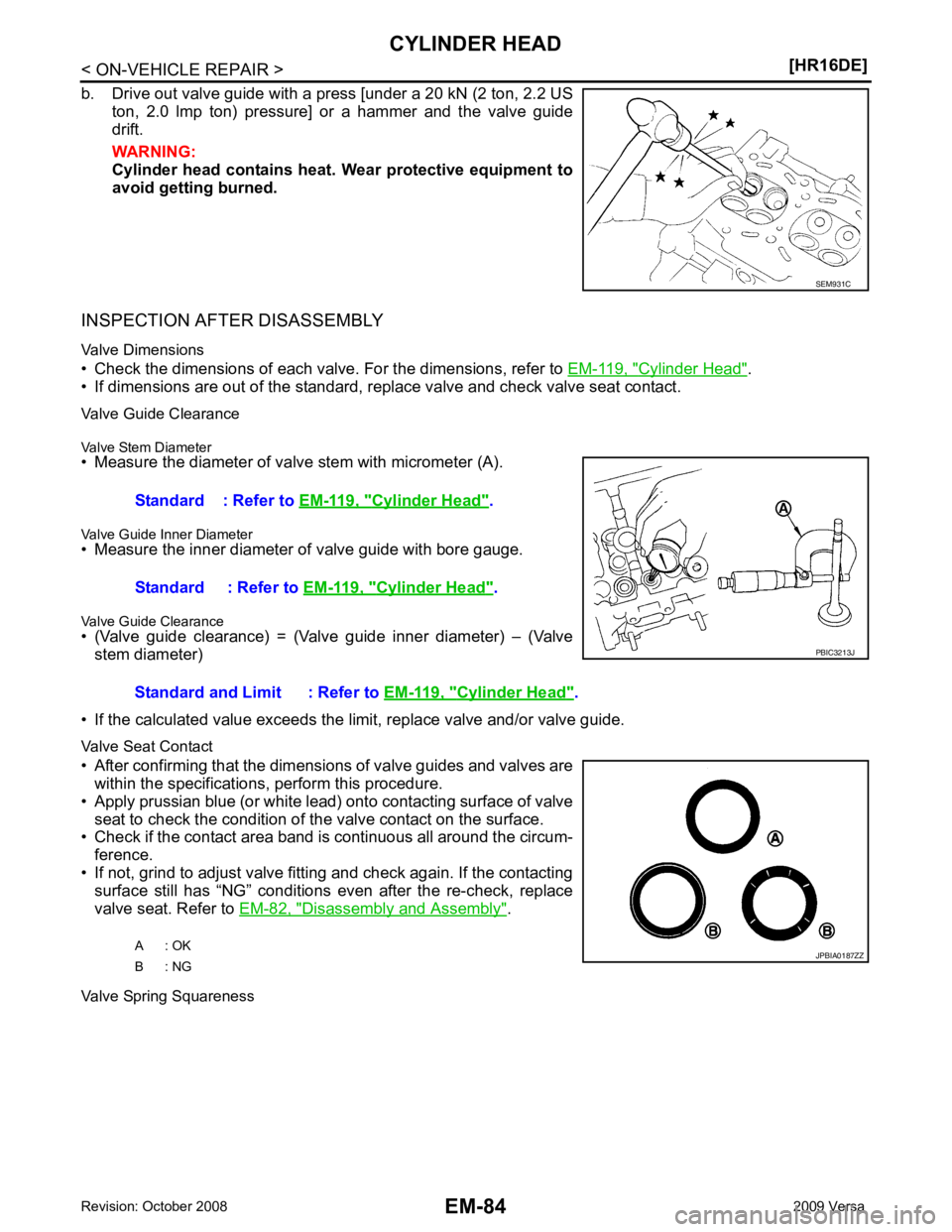
• If the calculated value exceeds the limit, replace valve and/or valve guide.
Valve Seat Contact
• After confirming that the dimensi ons of valve guides and valves are
within the specifications, perform this procedure.
• Apply prussian blue (or white lead) onto contacting surface of valve seat to check the condition of the valve contact on the surface.
• Check if the contact area band is continuous all around the circum-
ference.
• If not, grind to adjust valve fitting and check again. If the contacting surface still has “NG” conditions even after the re-check, replace
valve seat. Refer to EM-82, " Disassembly and Assembly " .
Valve Spring Squareness Cylinder Head " .
Standard : Refer to EM-119, " Cylinder Head " .
Standard and Limit : Refer to EM-119, " Cylinder Head " .
Page 3032 of 4331

EM
NP
O
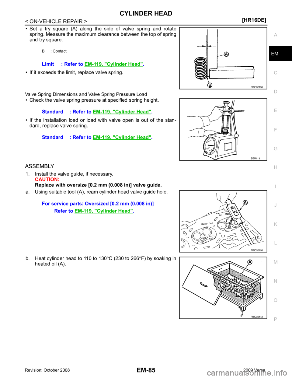
• Set a try square (A) along the side of valve spring and rotate
spring. Measure the maximum clearance between the top of spring
and try square.
• If it exceeds the limit, replace valve spring.
Valve Spring Dimensions and Valve Spring Pressure Load • Check the valve spring pressure at specified spring height.
• If the installation load or load with valve open is out of the stan- dard, replace valve spring.
ASSEMBLY 1. Install the valve guide, if necessary. CAUTION:
Replace with oversize [0.2 mm (0.008 in)] valve guide.
a. Using suitable tool (A), ream cylinder head valve guide hole.
b. Heat cylinder head to 110 to 130 °C (230 to 266 °F) by soaking in
heated oil (A). B : Contact
Limit : Refer to EM-119, " Cylinder Head " .
Cylinder Head " .
Standard : Refer to EM-119, " Cylinder Head " .
Cylinder Head " .
PBIC3214J
Page 3033 of 4331
![NISSAN TIIDA 2009 Service Repair Manual EM-86< ON-VEHICLE REPAIR >
[HR16DE]
CYLINDER HEAD
c. Using suitable tool, press valve guide (1) from camshaft side to the dimensions as shown.
WARNING:
Cylinder head (2) contains h eat. Wear protectiv NISSAN TIIDA 2009 Service Repair Manual EM-86< ON-VEHICLE REPAIR >
[HR16DE]
CYLINDER HEAD
c. Using suitable tool, press valve guide (1) from camshaft side to the dimensions as shown.
WARNING:
Cylinder head (2) contains h eat. Wear protectiv](/manual-img/5/57398/w960_57398-3032.png)
EM-86< ON-VEHICLE REPAIR >
[HR16DE]
CYLINDER HEAD
c. Using suitable tool, press valve guide (1) from camshaft side to the dimensions as shown.
WARNING:
Cylinder head (2) contains h eat. Wear protective equipment
to avoid getting burned.
d. Using suitable tool (A), apply reamer finish to valve guide.
2. Install the valve seat, if necessary. CAUTION:
Replace with oversize [0.5 mm (0.020 in)] valve seat.
a. Ream cylinder head recess diameter (a) for service valve seat.
• Be sure to ream in circles concentric to valve guide center.This will enable valve to fit correctly.
b. Heat cylinder head to 110 to 130 °C (230 to 266 °F) by soaking in
heated oil (A).
c. Provide valve seats cooled well with dry ice. Force fit valve seat into cylinder head. WARNING:
• Cylinder head contains heat. Wear prot ective equipment to avoid getting burned.
• Avoid directly touching cold valve seats. Projection “H”: Refer to
EM-119, " Cylinder Head " .
PBIC3217J
Standard: Refer to
EM-119, " Cylinder Head " .
PBIC3215J
For service parts: Oversize [0.5 mm (0.020 in)]
Refer to EM-119, " Cylinder Head " .
JPBIA0188ZZ
PBIC3214J
Page 3034 of 4331
![NISSAN TIIDA 2009 Service Repair Manual CYLINDER HEAD
EM-87
< ON-VEHICLE REPAIR >
[HR16DE] C
D E
F
G H
I
J
K L
M A EM
NP
O
d. Using suitable tool or valve seat grinder, finish seat to the speci-
fied dimensions. Refer to EM-119, " Cylinder NISSAN TIIDA 2009 Service Repair Manual CYLINDER HEAD
EM-87
< ON-VEHICLE REPAIR >
[HR16DE] C
D E
F
G H
I
J
K L
M A EM
NP
O
d. Using suitable tool or valve seat grinder, finish seat to the speci-
fied dimensions. Refer to EM-119, " Cylinder](/manual-img/5/57398/w960_57398-3033.png)
CYLINDER HEAD
EM-87
< ON-VEHICLE REPAIR >
[HR16DE] C
D E
F
G H
I
J
K L
M A EM
NP
O
d. Using suitable tool or valve seat grinder, finish seat to the speci-
fied dimensions. Refer to EM-119, " Cylinder Head " .
CAUTION:
When using the valve seat cutt er, firmly grip cutter handle
with both hands. Then, press on the contacting surface all
around the circumference to cu t in a single drive. Improper
pressure on with cutter or cu tting many different times may
result in stage valve seat.
e. Using compound, grind to adjust valve fitting.
f. Check again for normal contact. Refer to EM-82, " Disassembly and Assembly " .
3. Install valve oil seal. • Install with Tool (A) to match dimension as shown.
4. Install valve spring seat.
5. Install valve. • Install larger diameter to intake side.
6. Install valve spring. NOTE:
It can be installed in either direction.
7. Install valve spring retainer.
8. Install valve collet. • Compress valve spring with Tool (A). Install valve collet with amagnet hand (B).
CAUTION:
Be careful not to damage valve lifter holes.
• Tap valve stem edge lightly with a plastic hammer after instal-
lation to check its installed condition.
9. Install valve lifter.
10. Install spark plug with a suitable tool. SEM934C
Height “H” : 13.2 - 13.8 mm (0.520 - 0.543 in)
Tool number : KV10115600 (J-38958) PBIC3211J
Tool number : KV10116200 (J-26336-B)
: KV10115900 (J-26336-20)
: KV10109220 ( — ) PBIC3727E
Page 3057 of 4331
![NISSAN TIIDA 2009 Service Repair Manual EM-110< DISASSEMBLY AND ASSEMBLY >
[HR16DE]
CYLINDER BLOCK
CONNECTING ROD BEARING CRUSH HEIGHT
• When connecting rod bearing cap is removed after being tightened to the specified torque with co NISSAN TIIDA 2009 Service Repair Manual EM-110< DISASSEMBLY AND ASSEMBLY >
[HR16DE]
CYLINDER BLOCK
CONNECTING ROD BEARING CRUSH HEIGHT
• When connecting rod bearing cap is removed after being tightened to the specified torque with co](/manual-img/5/57398/w960_57398-3056.png)
EM-110< DISASSEMBLY AND ASSEMBLY >
[HR16DE]
CYLINDER BLOCK
CONNECTING ROD BEARING CRUSH HEIGHT
• When connecting rod bearing cap is removed after being tightened to the specified torque with connecting rod bearings installed, the
tip end of bearing must protrude. Refer to EM-96, " Disassembly
and Assembly " .
• If the standard is not met, replace connecting rod bearings.
MAIN BEARING CAP BOLT OUTER DIAMETER
• Measure the outer diameters (“d 1”, “d 2”) at two positions as shown.
• If reduction appears in a position other than “d 2 ”, regard it as “d 2”.
• If it exceeds the limit (a large difference in dimensions), replace main bearing cap bolt with a new one.
CONNECTING ROD CAP BOLT OUTER DIAMETER
• Measure the outer diameter “d” at position as shown.
• If reduction appears in a position other than “d”, regard it as “d”.
• When “d” falls below the limit (when it becomes thinner), replace connecting rod cap bolt with a new one.
FLYWHEEL DEFLECTION
• Measure the deflection of flywheel contact surface to clutch with a
dial indicator.
• If measured value is out of the standard, replace flywheel. Standard: There must be crush height. PBIC1646E
Limit (“d
1”–“d 2”): 0.2 mm (0.008 in) PBIC3768E
Limit: 7.75 mm (0.3051 in)
PBIC3769E
Standard : 0.25 mm (0.0098 in) or less.
PBIC2646E
Page 3058 of 4331

EM
NP
O
HOW TO SELECT PISTON AND BEARING
Description INFOID:0000000004784319
• The identification grade stamped on each part is the grade for the dimension measured in new condition.
This grade cannot apply to reused parts.
• For reused or repaired parts, measure the dimens ion accurately. Determine the grade by comparing the
measurement with the values of each selection table.
• For details of the measurement method of each part , the reuse standards and the selection method of the
selective fitting parts, follow the procedures.
Connecting Rod Bearing INFOID:0000000004784320
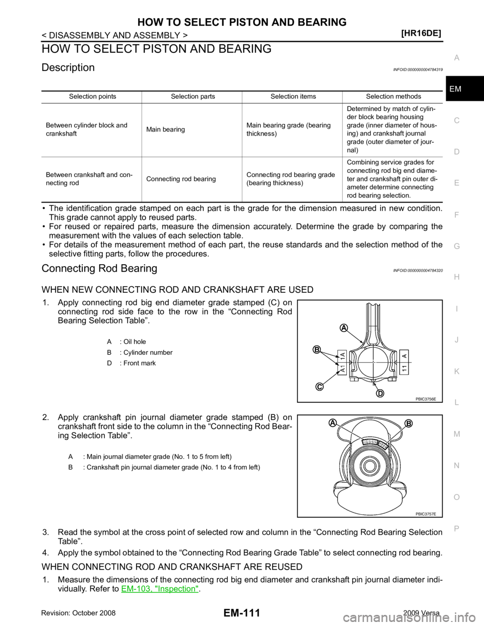
WHEN NEW CONNECTING ROD AND CRANKSHAFT ARE USED 1. Apply connecting rod big end diameter grade stamped (C) on connecting rod side face to the row in the “Connecting Rod
Bearing Selection Table”.
2. Apply crankshaft pin journal diameter grade stamped (B) on crankshaft front side to the column in the “Connecting Rod Bear-
ing Selection Table”.
3. Read the symbol at the cross point of selected ro w and column in the “Connecting Rod Bearing Selection
Table”.
4. Apply the symbol obtained to the “Connecting Rod Bear ing Grade Table” to select connecting rod bearing.
WHEN CONNECTING ROD AND CRANKSHAFT ARE REUSED 1. Measure the dimensions of the connecting rod big end diameter and crankshaft pin journal diameter indi-
vidually. Refer to EM-103, " Inspection " .
Selection points Selection parts Selection items Selection methods
Between cylinder block and
crankshaft Main bearing Main bearing grade (bearing
thickness) Determined by match of cylin-
der block bearing housing
grade (inner diameter of hous-
ing) and crankshaft journal
grade (outer diameter of jour-
nal)
Between crankshaft and con-
necting rod Connecting rod bearing Connecting rod bearing grade
(bearing thickness) Combining service grades for
connecting rod big end diame-
ter and crankshaft pin outer di-
ameter determine connecting
rod bearing selection. A : Oil hole
B : Cylinder number
D : Front mark
Page 3060 of 4331
![NISSAN TIIDA 2009 Service Repair Manual HOW TO SELECT PISTON AND BEARING
EM-113
< DISASSEMBLY AND ASSEMBLY >
[HR16DE] C
D E
F
G H
I
J
K L
M A EM
NP
O
In grinding crankshaft pin to
use undersize bearings, keep the
fillet R (A) [0.8 NISSAN TIIDA 2009 Service Repair Manual HOW TO SELECT PISTON AND BEARING
EM-113
< DISASSEMBLY AND ASSEMBLY >
[HR16DE] C
D E
F
G H
I
J
K L
M A EM
NP
O
In grinding crankshaft pin to
use undersize bearings, keep the
fillet R (A) [0.8](/manual-img/5/57398/w960_57398-3059.png)
HOW TO SELECT PISTON AND BEARING
EM-113
< DISASSEMBLY AND ASSEMBLY >
[HR16DE] C
D E
F
G H
I
J
K L
M A EM
NP
O
In grinding crankshaft pin to
use undersize bearings, keep the
fillet R (A) [0.8 - 1.2 mm (0.031 - 0.047 in)].
Main Bearing INFOID:0000000004784321
HOW TO SELECT MAIN BEARING
When New Cylinder Block and Crankshaft Are Used
1. “Main Bearing Selection Table” rows correspond to main bearing housing grade on left side of cylinder block.
• If there is a corrected stamp mark (B) on cylinder block, use it as a correct reference.
2. Apply main journal diameter grade stamped on crankshaft front side to column in the “Main Bearing Selection Table”.
3. Read the symbol at the cross point of selected row and column in the “Main Bearing Selection Table”.
4. Apply the symbol obtained to the “Main B earing Grade Table” to select main bearing.
NOTE:
Service part is available as a set of both upper and lower.
When Cylinder Block and Crankshaft Are Reused 1. Measure the dimensions of the cylinder block ma in bearing housing inner diameter and crankshaft main
journal diameter individually. Refer to EM-103, " Inspection " .
2. Apply the measured dimension to t he “Main Bearing Selection Table”.
3. Read the symbol at the cross point of selected row and column in the “Main Bearing Selection Table”.
4. Apply the symbol obtained to the “Main B earing Grade Table” to select main bearing.
Bearing undersize table:
Refer to EM-124, " Connecting Rod Bearing " .
PBIC3263J
A : Basic stamp mark
: Engine front PBIC3760E
A : Main journal diameter grade (No. 1 to 5 from left)
B : Crankshaft pin journal diameter grade (No. 1 to 4 from left) PBIC3757E