2009 NISSAN TIIDA Power Window
[x] Cancel search: Power WindowPage 1463 of 4331

EC
NP
O
HO2S2 (B1) V
• The signal voltage of the heated oxygen sensor 2 is
displayed.
HO2S2 MNTR(B1) RICH/
LEAN • Display of heated oxygen sensor 2 signal:
RICH: means the amount of oxygen after three way
catalyst is relatively small.
LEAN: means the amount of oxygen after three way
catalyst is relatively large. • When the engine is stopped, a certain
value is indicated.
VHCL SPEED SE km/h or
mph • The vehicle speed computed from the vehicle speed
signal sent from combination meter is displayed.
BATTERY VOLT V • The power supply voltage of ECM is displayed.
ACCEL SEN 1 V• The accelerator pedal position sensor signal voltage is
displayed. • ACCEL SEN 2 signal is converted by
ECM internally. Thus, it differs from
ECM terminal voltage signal.
ACCEL SEN 2
TP SEN 1-B1 V• The throttle position sensor signal voltage is dis-
played. • TP SEN 2-B1 signal is converted by
ECM internally. Thus, it differs from
ECM terminal voltage signal.
TP SEN 2-B1
FUEL T/TMP SE °C or °F • The fuel temperature (determined by the signal volt-
age of the fuel tank temperature sensor) is displayed.
INT/A TEMP SE °C or °F • The intake air temperature (determined by the signal
voltage of the intake air temperature sensor) is indicat-
ed.
EVAP SYS PRES V • The signal voltage of EVAP control system pressure
sensor is displayed.
FUEL LEVEL SE V • The signal voltage of the fuel level sensor is displayed.
START SIGNAL ON/OFF • Indicates start signal status [ON/OFF] computed by
the ECM according to the signals of engine speed and
battery voltage. • After starting the engine, [OFF] is dis-
played regardless of the starter sig-
nal.
CLSD THL POS ON/OFF • Indicates idle position [ON/OFF] computed by ECM
according to the accelerator pedal position sensor sig-
nal.
AIR COND SIG ON/OFF • Indicates [ON/OFF] condition of the air conditioner
switch determined by the air conditioner ON signal.
P/N POSI SW ON/OFF • Indicates [ON/OFF] condit
ion from the park/neutral
position (PNP) switch signal.
PW/ST SIGNAL ON/OFF • [ON/OFF] condition of the power steering system (de-
termined by the signal sent from EPS control unit) is
indicated.
LOAD SIGNAL ON/OFF • Indicates [ON/OFF] condition from the electrical load
signal.
ON: Rear window defogger switch is ON and/or light-
ing switch is in 2nd position.
OFF: Both rear window defogger switch and lighting
switch are OFF.
IGNITION SW ON/OFF • Indicates [ON/OFF] condition from ignition switch sig-
nal.
HEATER FAN SW ON/OFF • Indicates [ON/OFF] condition from the heater fan
switch signal.
BRAKE SW ON/OFF • Indicates [ON/OFF] condition from the stop lamp
switch signal.
INJ PULSE-B1 msec • Indicates the actual fuel injection pulse width compen-
sated by ECM according to the input signals. • When the engine is stopped, a certain
computed value is indicated.
IGN TIMING BTDC • Indicates the ignition timing computed by ECM ac-
cording to the input signals. • When the engine is stopped, a certain
value is indicated.
CAL/LD VALUE % • “Calculated load value” indicates the value of the cur-
rent air flow divided by peak air flow.
Monitored item Unit Description Remarks
Page 1965 of 4331
![NISSAN TIIDA 2009 Service Repair Manual EC
NP
O
FUEL T/TMP SE
[ ° C] or [ °F] • The fuel temperature (determined by the signal voltage of the
fuel tank temperature sensor) is displayed.
INT/A TEMP SE
[ ° C] or [ °F] • The intake ai NISSAN TIIDA 2009 Service Repair Manual EC
NP
O
FUEL T/TMP SE
[ ° C] or [ °F] • The fuel temperature (determined by the signal voltage of the
fuel tank temperature sensor) is displayed.
INT/A TEMP SE
[ ° C] or [ °F] • The intake ai](/manual-img/5/57398/w960_57398-1964.png)
EC
NP
O
FUEL T/TMP SE
[ ° C] or [ °F] • The fuel temperature (determined by the signal voltage of the
fuel tank temperature sensor) is displayed.
INT/A TEMP SE
[ ° C] or [ °F] • The intake air temperature (determined by the signal voltage
of the intake air temperature sensor) is indicated.
EVAP SYS PRES
[V] • The signal voltage of EVAP control system pressure sensor
is displayed.
FUEL LEVEL SE
[V] • The signal voltage of the fuel level sensor is displayed.
START SIGNAL
[ON/OFF] • Indicates start signal status [ON/OFF] computed by the ECM
according to the signals of engine speed and battery voltage. • After starting the engine, [OFF] is displayed
regardless of the starter signal.
CLSD THL POS
[ON/OFF] • Indicates idle position [ON/OFF] computed by the ECM ac-
cording to the accelerator pedal position sensor signal.
AIR COND SIG
[ON/OFF] • Indicates [ON/OFF] condition of the air conditioner switch as
determined by the air conditioner signal.
P/N POSI SW
[ON/OFF] • Indicates [ON/OFF] condition from the park/neutral position
(PNP) switch signal.
PW/ST SIGNAL
[ON/OFF] • [ON/OFF] condition of the power steering system (deter-
mined by the signal sent from EPS control unit) is indicated.
LOAD SIGNAL
[ON/OFF] • Indicates [ON/OFF] condition from the electrical load signal.
ON: Rear window defogger switch is ON and/or lighting
switch is in 2nd position.
OFF: Both rear window defogger switch and lighting switch
are OFF.
IGNITION SW
[ON/OFF] • Indicates [ON/OFF] condition from ignition switch.
HEATER FAN SW
[ON/OFF] • Indicates [ON/OFF] condition from the heater fan switch sig-
nal.
BRAKE SW
[ON/OFF] • Indicates [ON/OFF] condition from the stop lamp switch sig-
nal.
INJ PULSE-B1
[msec] • Indicates the actual fuel injection pulse width compensated
by ECM according to the input signals. • When the engine is stopped, a certain com-
puted value is indicated.
IGN TIMING
[BTDC] • Indicates the ignition timing computed by ECM according to
the input signals. • When the engine is stopped, a certain value
is indicated.
CAL/LD VALUE
[%] • “Calculated load value” indicates the value of the current air-
flow divided by peak airflow.
MASS AIRFLOW
[g·m/s] • Indicates the mass airflow computed by ECM according to
the signal voltage of the mass air flow sensor.
PURG VOL C/V
[%] • Indicates the EVAP canister purge volume control solenoid
valve control value computed by the ECM according to the in-
put signals.
• The opening becomes larger as the value increases.
INT/V TIM (B1)
[ ° CA] • Indicates [
°CA] of intake camshaft advanced angle.
INT/V SOL (B1)
[%] • The control value of the intake valve timing control solenoid
valve (determined by ECM according to the input signal) is in-
dicated.
• The advance angle becomes larger as the value increases
AIR COND RLY
[ON/OFF] • The air conditioner relay control condition (determined by
ECM according to the input signals) is indicated.
FUEL PUMP RLY
[ON/OFF] • Indicates the fuel pump relay control condition determined by
ECM according to the input signals.
Monitored item [Unit] Description Remarks
Page 2477 of 4331
![NISSAN TIIDA 2009 Service Repair Manual EC
NP
O
FUEL T/TMP SE
[ ° C] or [ °F] • The fuel temperature (determined by the signal voltage of the
fuel tank temperature sensor) is displayed.
INT/A TEMP SE
[ ° C] or [ °F] • The intake ai NISSAN TIIDA 2009 Service Repair Manual EC
NP
O
FUEL T/TMP SE
[ ° C] or [ °F] • The fuel temperature (determined by the signal voltage of the
fuel tank temperature sensor) is displayed.
INT/A TEMP SE
[ ° C] or [ °F] • The intake ai](/manual-img/5/57398/w960_57398-2476.png)
EC
NP
O
FUEL T/TMP SE
[ ° C] or [ °F] • The fuel temperature (determined by the signal voltage of the
fuel tank temperature sensor) is displayed.
INT/A TEMP SE
[ ° C] or [ °F] • The intake air temperature (determined by the signal voltage
of the intake air temperature sensor) is indicated.
EVAP SYS PRES
[V] • The signal voltage of EVAP control system pressure sensor
is displayed.
FUEL LEVEL SE
[V] • The signal voltage of the fuel level sensor is displayed.
START SIGNAL
[ON/OFF] • Indicates start signal status [ON/OFF] computed by the ECM
according to the signals of engine speed and battery voltage. • After starting the engine, [OFF] is displayed
regardless of the starter signal.
CLSD THL POS
[ON/OFF] • Indicates idle position [ON/OFF] computed by the ECM ac-
cording to the accelerator pedal position sensor signal.
AIR COND SIG
[ON/OFF] • Indicates [ON/OFF] condition of the air conditioner switch as
determined by the air conditioner signal.
P/N POSI SW
[ON/OFF] • Indicates [ON/OFF] condition from the park/neutral position
(PNP) switch signal.
PW/ST SIGNAL
[ON/OFF] • [ON/OFF] condition of the power steering system (deter-
mined by the signal sent from EPS control unit) is indicated.
LOAD SIGNAL
[ON/OFF] • Indicates [ON/OFF] condition from the electrical load signal.
ON: Rear window defogger switch is ON and/or lighting
switch is in 2nd position.
OFF: Both rear window defogger switch and lighting switch
are OFF.
IGNITION SW
[ON/OFF] • Indicates [ON/OFF] condition from ignition switch.
HEATER FAN SW
[ON/OFF] • Indicates [ON/OFF] condition from the heater fan switch sig-
nal.
BRAKE SW
[ON/OFF] • Indicates [ON/OFF] condition from the stop lamp switch sig-
nal.
INJ PULSE-B1
[msec] • Indicates the actual fuel injection pulse width compensated
by ECM according to the input signals. • When the engine is stopped, a certain com-
puted value is indicated.
IGN TIMING
[BTDC] • Indicates the ignition timing computed by ECM according to
the input signals. • When the engine is stopped, a certain value
is indicated.
CAL/LD VALUE
[%] • “Calculated load value” indicates the value of the current air-
flow divided by peak airflow.
MASS AIRFLOW
[g·m/s] • Indicates the mass airflow computed by ECM according to
the signal voltage of the mass air flow sensor.
PURG VOL C/V
[%] • Indicates the EVAP canister purge volume control solenoid
valve control value computed by the ECM according to the in-
put signals.
• The opening becomes larger as the value increases.
INT/V TIM (B1)
[ ° CA] • Indicates [
°CA] of intake camshaft advanced angle.
INT/V SOL (B1)
[%] • The control value of the intake valve timing control solenoid
valve (determined by ECM according to the input signal) is in-
dicated.
• The advance angle becomes larger as the value increases
AIR COND RLY
[ON/OFF] • The air conditioner relay control condition (determined by
ECM according to the input signals) is indicated.
FUEL PUMP RLY
[ON/OFF] • Indicates the fuel pump relay control condition determined by
ECM according to the input signals.
Monitored item [Unit] Description Remarks
Page 2926 of 4331

EI
N
O P
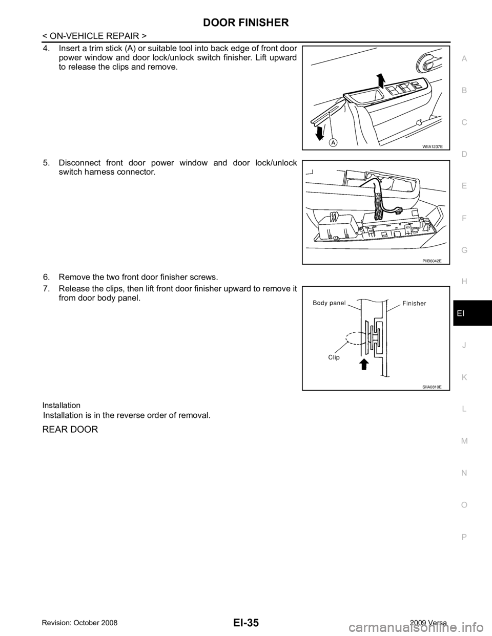
4. Insert a trim stick (A) or suitable tool into back edge of front door
power window and door lock/unlock switch finisher. Lift upward
to release the clips and remove.
5. Disconnect front door power window and door lock/unlock switch harness connector.
6. Remove the two front door finisher screws.
7. Release the clips, then lift front door finisher upward to remove it from door body panel.
Installation Installation is in the reverse order of removal.
REAR DOOR PIIB6042E
Page 3304 of 4331

GW
N
O P
CONTENTS
GLASSES, WINDOW SYSTEM & MIRRORS
SERVICE INFORMATION .. ..........................3
PRECAUTIONS .............................................. .....3
Precaution for Supplemental Restraint System
(SRS) "AIR BAG" and "SEAT BELT PRE-TEN-
SIONER" ............................................................. ......
3
Precaution Necessary fo r Steering Wheel Rota-
tion After Battery Disconnect ............................... ......
3
Precaution for Procedure without Cowl Top Cover ......4
Handling for Adhesive and Primer ...................... ......4
PREPARATION .............................................. .....5
Commercial Service Tool .................................... ......5
SQUEAK AND RATTLE TROUBLE DIAG-
NOSES ........................ ........................................6
Work Flow ........................................................... ......6
Generic Squeak and Rattle Troubleshooting ...... ......8
Diagnostic Worksheet ......................................... ....10
WINDSHIELD GLASS .................................... ....12
Removal and Installation .........................................12
OPERA WINDOW GLASS ............................. ....14
Removal and Installation .........................................14
REAR WINDOW GLASS AND MOLDING ..... ....16
Removal and Installation .........................................16
POWER WINDOW SYST EM ..............................19
Component Parts and Harness Connector Loca-
tion ...................................................................... ....
19
System Description ............................................. ....19
CAN Communication System Description ........... ....23
Schematic ........................................................... ....24
Wiring Diagram - WINDOW- ............................... ....25
Main Power Window and Door Lock/Unlock
Switch Harness Connector Terminal Layout ....... ....
29
Terminal and Reference Value for Main Power
Window and Door Lock/Unlock Switch ............... ....
29
Terminal and Reference Value for BCM ............. ....30
Work Flow ........................................................... ....30 CONSULT-III Function (B
CM) .................................30
Power Window Auto Operat ion Initialization ............31
Trouble Diagnosis Symptom Chart ...................... ....31
BCM Power Supply and Ground Circuit Inspection ....32
Main Power Window and Door Lock/Unlock
Switch Power Supply and Ground Circuit Inspec-
tion ....................................................................... ....
32
Front Power Window Motor LH Circuit Inspection ....33
Front Power Window RH Circuit Inspection (Pow-
er Window and Door Lock/Unlock Switch RH Op-
eration) ................................................................ ....
34
Front Power Window Motor RH Circuit Inspection ....34
Encoder Circuit Inspection ................................... ....36
Door Switch Check .............................................. ....38
Rear Power Window LH Circuit Inspection (Rear
Power Window Switch LH Operation) ................. ....
39
Rear Power Window RH Circu it Inspection (Rear
Power Window Switch RH Operation) ................. ....
40
Rear Power Window Motor LH Circuit Inspection ....40
Rear Power Window Motor RH Circuit Inspection ....42
FRONT DOOR GLASS AND REGULATOR ..... 44
Removal and Installation ..................................... ....44
Disassembly and Assembly ................................. ....46
Inspection after Installati on ......................................46
REAR DOOR GLASS AND REGULATOR ....... 48
Removal and Installation ..................................... ....48
Disassembly and Assembly ................................. ....50
Inspection after Installati on ......................................50
REAR WINDOW DEFOGGER .......................... 51
Component Parts and Harness Connector Loca-
tion ....................................................................... ....
51
System Description .............................................. ....51
CAN Communication System Description ........... ....52
Wiring Diagram - DEF - ....................................... ....53
Terminal and Reference Value for BCM ..................55
Terminal and Reference Va lue for IPDM E/R ..........55
Work Flow ............................................................ ....55
Page 3316 of 4331

GW
N
O P
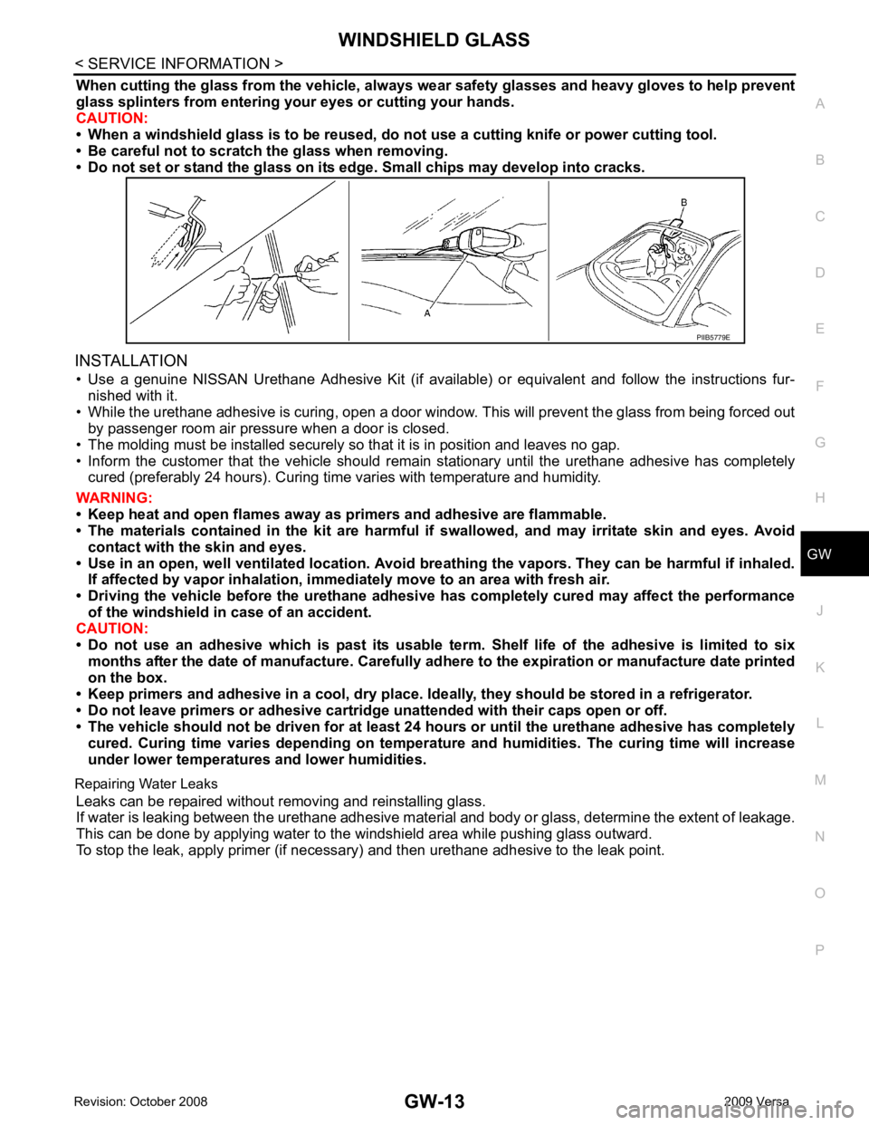
When cutting the glass from the vehicle, always
wear safety glasses and heavy gloves to help prevent
glass splinters from entering your eyes or cutting your hands.
CAUTION:
• When a windshield glass is to be reused, do no t use a cutting knife or power cutting tool.
• Be careful not to scratch the glass when removing.
• Do not set or stand the glass on its ed ge. Small chips may develop into cracks.
INSTALLATION • Use a genuine NISSAN Urethane Adhesive Kit (if availabl e) or equivalent and follow the instructions fur-
nished with it.
• While the urethane adhesive is curing, open a door window . This will prevent the glass from being forced out
by passenger room air pressure when a door is closed.
• The molding must be installed securely so that it is in position and leaves no gap.
• Inform the customer that the vehicle should rema in stationary until the urethane adhesive has completely
cured (preferably 24 hours). Curing time varies with temperature and humidity.
WARNING:
• Keep heat and open flames away as primers and adhesive are flammable.
• The materials contained in the kit are harmful if swallowed, and may irritate skin and eyes. Avoid
contact with the skin and eyes.
• Use in an open, well ventilated lo cation. Avoid breathing the vapors. They can be harmful if inhaled.
If affected by vapor inhalation, imme diately move to an area with fresh air.
• Driving the vehicle before the urethane adhesive has completely cured may affect the performance
of the windshield in case of an accident.
CAUTION:
• Do not use an adhesive which is past its usable te rm. Shelf life of the adhesive is limited to six
months after the date of manufacture. Carefully ad here to the expiration or manufacture date printed
on the box.
• Keep primers and adhesive in a cool, dry place. Id eally, they should be stored in a refrigerator.
• Do not leave primers or adhesive cartridge unattended with their caps open or off.
• The vehicle should not be driven for at least 24 hours or until the urethane adhesive has completely
cured. Curing time varies depend ing on temperature and humidities. The curing time will increase
under lower temperatures and lower humidities.
Repairing Water Leaks Leaks can be repaired without removing and reinstalling glass.
If water is leaking between the urethane adhesive material and body or glass, determine the extent of leakage.
This can be done by applying water to the windshield area while pushing glass outward.
To stop the leak, apply primer (if necessary ) and then urethane adhesive to the leak point.
Page 3317 of 4331

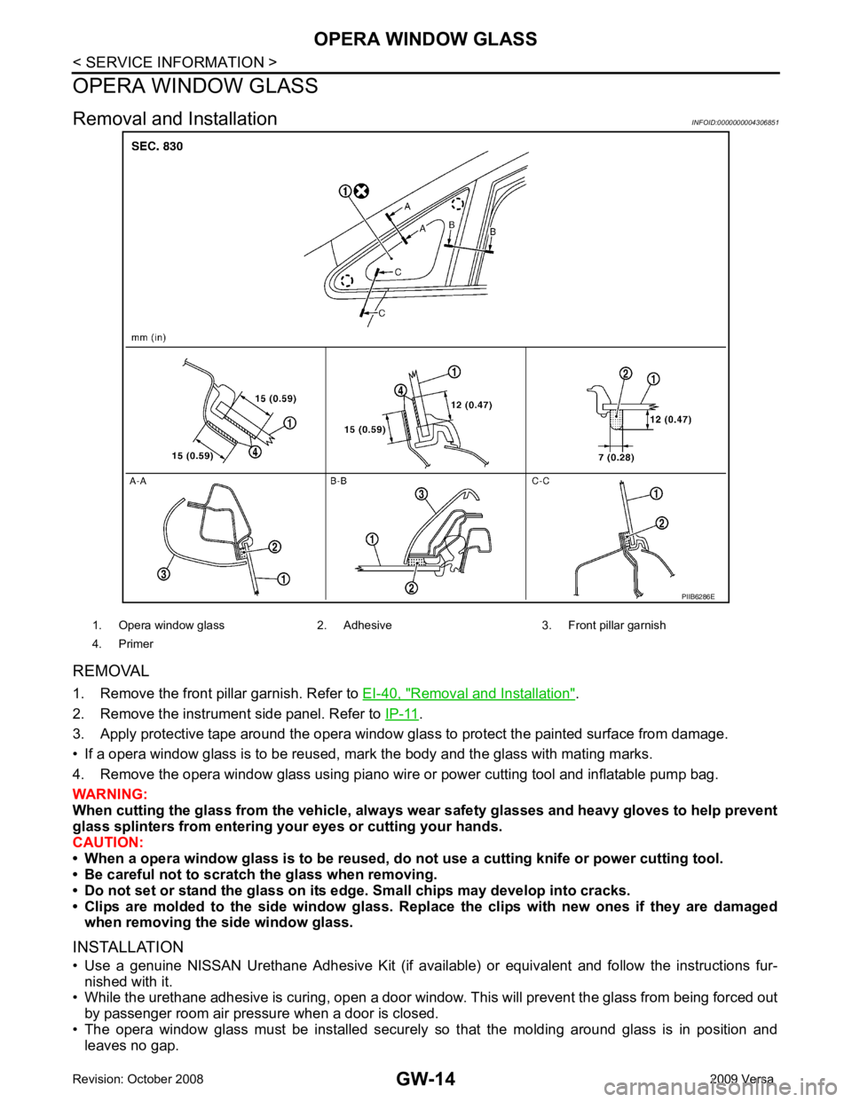
Removal and Installation " .
2. Remove the instrument side panel. Refer to IP-11 .
3. Apply protective tape around the opera window glas s to protect the painted surface from damage.
• If a opera window glass is to be reused, mark the body and the glass with mating marks.
4. Remove the opera window glass using piano wire or power cutting tool and inflatable pump bag.
WARNING:
When cutting the glass from the vehicle, always wear safety glasses and heavy gloves to help prevent
glass splinters from entering your eyes or cutting your hands.
CAUTION:
• When a opera window glass is to be reused, do not use a cutting knife or power cutting tool.
• Be careful not to scratch the glass when removing.
• Do not set or stand the glass on its edge. Small chips may develop into cracks.
• Clips are molded to the side window glass. Re place the clips with new ones if they are damaged
when removing the side window glass.
INSTALLATION
• Use a genuine NISSAN Urethane Adhesive Kit (if available) or equivalent and follow the instructions fur- nished with it.
• While the urethane adhesive is curing, open a door window . This will prevent the glass from being forced out
by passenger room air pressure when a door is closed.
• The opera window glass must be installed securely so that the molding around glass is in position and
leaves no gap.
Page 3320 of 4331

GW
N
O P
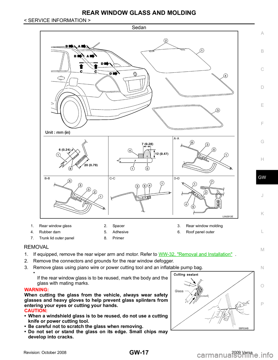
Sedan
REMOVAL 1. If equipped, remove the rear wiper arm and motor. Refer to WW-32, " Removal and Installation " .
2. Remove the connectors and grounds for the rear window defogger.
3. Remove glass using piano wire or power cutting tool and an inflatable pump bag. •
If the rear window glass is to be reused, mark the body and the
glass with mating marks.
WARNING:
When cutting the glass from th e vehicle, always wear safety
glasses and heavy gloves to help prevent glass splinters from
entering your eyes or cutting your hands.
CAUTION:
• When a windshield glass is to be reused, do not use a cutting knife or power cutting tool.
• Be careful not to scratch the glass when removing.
• Do not set or stand the glass on its edge. Small chips may develop into cracks.