Page 3322 of 4331
GW
N
O P
POWER WINDOW SYSTEM
Component Parts and Har ness Connector Location INFOID:0000000004306853
System Description INFOID:0000000004306854
Power is supplied at all times
• through 40A fusible link (letter g , located in the fuse and fusible link box)
• to BCM terminal 70.
With ignition switch in ON or START position, power is supplied
• through 10A fuse [No. 6, located in the fuse block (J/B)]
• to BCM terminal 38 1. Main power window and door lock/
unlock switch D7, D8 2. Power window and door lock/unlock
switch RH D105 3. Rear power window switch LH D203,
RH D303
4. BCM M18, M19, M20 (view with glove box removed) 5. Front power window motor LH D9,
RH D104 6. Rear power window motor LH D204,
RH D304
7. Front door switch LH B8, RH B108
Page 3324 of 4331

GW
N
O P
• through main power window and door lock/unlock switch terminal 12
• to power window and door lock/unlock switch RH terminal 11
• through power window and door lock/unlock switch LH terminal 6
• to front power window motor RH terminal 1.
Then, the motor raises the window until the switch is released.
WINDOW DOWN
When the main power window and door lock/unlock switch (f ront RH) is pressed in the down position, power is
supplied
• through main power window and door lock/unlock switch terminal 12
• to power window and door lock/unlock switch LH terminal 11
• through power window and door lock/unlock switch LH terminal 6
• to front power window motor RH terminal 1.
Ground is supplied
• through main power window and door lock/unlock switch terminal 16
• to power window and door lock/unlock switch RH terminal 12
• through power window and door lock/unlock switch LH terminal 7
• to front power window motor RH terminal 2.
Then, the motor lowers the window until the switch is released.
Rear Door (LH or RH) REAR POWER WINDOW SWITCH LH OR RH OPERATION
WINDOW UP
When the rear power window switch LH or RH is pulled in the up position, power is supplied
• through rear power window switch LH or RH terminal 5
• to rear power window motor LH or RH terminal 2.
Ground is supplied
• through rear power window switch LH or RH terminal 4
• to rear power window motor LH or RH terminal 1.
Then, the motor raises the window until the switch is released.
WINDOW DOWN
When the rear power window switch LH or RH is pressed in the down position, power is supplied
• through rear power window switch LH or RH terminal 4
• to rear power window motor LH or RH terminal 1.
Ground is supplied
• through rear power window switch LH or RH terminal 5
• to rear power window motor LH or RH terminal 2.
Then, the motor lowers the window until the switch is released.
MAIN POWER WINDOW AND DOOR LOCK/UNLOCK SWITCH OPERATION
WINDOW UP
When the main power window and door lock/unlock switch (r ear LH) is pulled in the up position, power is sup-
plied
• through main power window and door lock/unlock switch terminal 1
• to rear power window switch LH terminal 2
• through rear power window switch LH terminal 5
• to rear power window motor LH terminal 2.
Ground is supplied
• through main power window and door lock/unlock switch terminal 3
• to rear power window switch LH terminal 3
• through rear power window switch LH terminal 4
• to rear power window motor LH terminal 1.
Then, the motor raises the window until the switch is released.
When the main power window and door lock/unlock switch (r ear RH) is pulled in the up position, power is sup-
plied
• through main power window and door lock/unlock switch terminal 7
• to rear power window switch RH terminal 2
• through rear power window switch RH terminal 5
• to rear power window motor RH terminal 2.
Ground is supplied
• through main power window and door lock/unlock switch terminal 5
• through rear power window switch RH terminal 3
• to rear power window switch RH terminal 4
• to rear power window motor RH terminal 1.
Page 3325 of 4331
CONSULT-III Function
(BCM) " .
ANTI-PINCH SYSTEM
Main power window and door lock/unlock switch monitors the power window motor operation and the power
window position (full closed or other) for front LH power window by the signal from encoder in front power win-
dow motor LH.
When main power window and door lock/unlock switch det ects interruption during the following close opera-
tions
• automatic close operation when igniti on switch is in the ON position
• automatic close operation during retained power operation
Main power window and door lock/unlock switch controls front power window motor LH for open and the
power window will be lowered.
Page 3332 of 4331
GW
N
O P
Main Power Window and Door Lock/Unlock
Switch Harness Connector Terminal Lay-
out INFOID:0000000004306858
Terminal and Reference Value for Main Po wer Window and Door Lock/Unlock Switch
INFOID:0000000004306859
Page 3333 of 4331

Terminal and Reference Value for BCM " .
Work Flow INFOID:0000000004306861
1. Check the symptom and customer's requests.
2. Understand the outline of system. Refer to GW-19, " System Description " .
3. According to the trouble diagnosis chart, repa ir or replace the cause of the malfunction.
Refer to GW-31, " Trouble Diagnosis Symptom Chart " .
4. Does power window system operate normally? If Yes, GO TO 5, If No, GO TO 3.
5. Inspection End.
CONSULT-III Function (BCM) INFOID:0000000004306862
CONSULT-III can display each diagnostic item us ing the diagnostic test modes shown following.
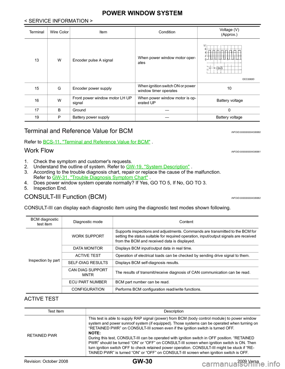
ACTIVE TEST 13 W Encoder pulse A signal
When power window motor oper-
ates
15 G Encoder power supply When ignition switch ON or power
window timer operates 10
16 W Front power window motor LH UP
signal When power window motor is op-
erated UP Battery voltage
17 B Ground — 0
19 P Battery power supply — Battery voltage
Terminal Wire Color Item Condition
Voltage (V)
(Approx.) Test Item Description
RETAINED PWR This test is able to supply RAP signal (powe
r) from BCM (body control module) to power window
system and power sunroof system (if equipped). Those systems can be operated when turning on
“RETAINED PWR” on CONSULT-III screen even if the ignition switch is turned OFF.
NOTE:
During this test, CONSULT-III can be operated with ignition switch in OFF position. “RETAINED
PWR” should be turned “ON” or “OFF” on CONSULT-III screen when ignition switch is ON. Then
turn ignition switch OFF to check retained power operation. CONSULT-III might be stuck if “RE-
TAINED PWR” is turned “ON” or “OFF” on CO NSULT-III screen when ignition switch is OFF.
Page 3334 of 4331

GW
N
O P
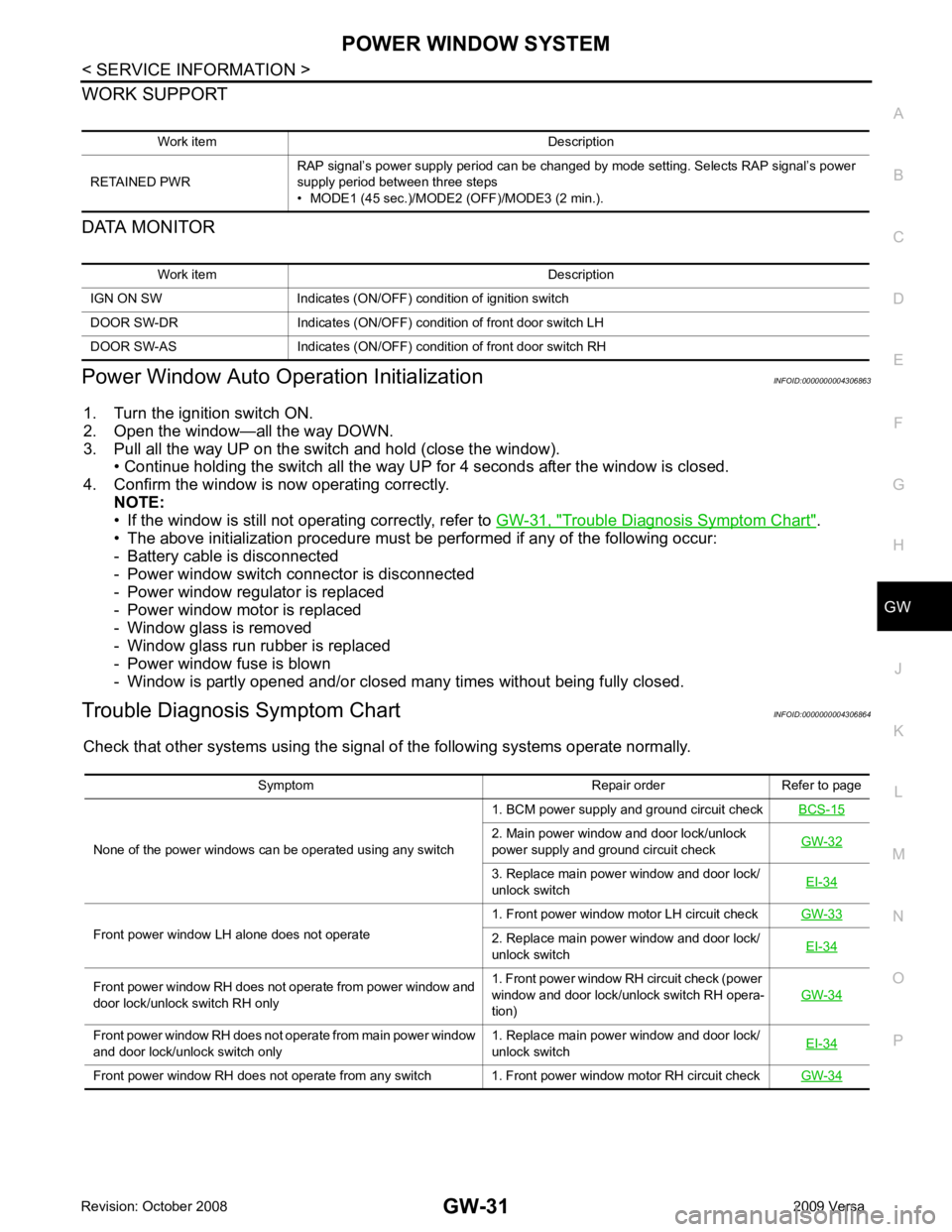
WORK SUPPORT
DATA MONITOR
Power Window Auto Operation Initialization INFOID:0000000004306863
1. Turn the ignition switch ON.
2. Open the window—all the way DOWN.
3. Pull all the way UP on the switch and hold (close the window). • Continue holding the switch all the way UP for 4 seconds after the window is closed.
4. Confirm the window is now operating correctly. NOTE:
• If the window is still not operating correctly, refer to GW-31, " Trouble Diagnosis Symptom Chart " .
• The above initialization procedure must be performed if any of the following occur:
- Battery cable is disconnected
- Power window switch connector is disconnected
- Power window regulator is replaced
- Power window motor is replaced
- Window glass is removed
- Window glass run rubber is replaced
- Power window fuse is blown
- Window is partly opened and/or closed many times without being fully closed.
Trouble Diagnosis Symptom Chart INFOID:0000000004306864
Check that other systems us ing the signal of the following systems operate normally.
Work item Description
RETAINED PWR RAP signal’s power supply period can be changed by mode setting. Selects RAP signal’s power
supply period between three steps
• MODE1 (45 sec.)/MODE2 (OFF)/MODE3 (2 min.). Work item Description
IGN ON SW Indicates (ON/OFF) condition of ignition switch
DOOR SW-DR Indicates (ON/OFF) condition of front door switch LH
DOOR SW-AS Indicates (ON/OFF) condition of front door switch RH Symptom Repair order Refer to page
None of the power windows can be operated using any switch 1. BCM power supply and ground circuit check
BCS-15 2. Main power window and door lock/unlock
power supply and ground circuit check GW-32 3. Replace main power window and door lock/
unlock switch EI-34Front power window LH alone does not operate
1. Front power window motor LH circuit check
GW-33 2. Replace main power window and door lock/
unlock switch EI-34Front power window RH does not operate from power window and
door lock/unlock switch RH only 1. Front power window RH circuit check (power
window and door lock/unlock switch RH opera-
tion) GW-34Front power window RH does not operate from main power window
and door lock/unlock switch only 1. Replace main power window and door lock/
unlock switch EI-34Front power window RH does not operate from any switch 1. Front power window motor RH circuit check
GW-34
Page 3335 of 4331

BCM Power Supply and Ground Circuit Inspection " .
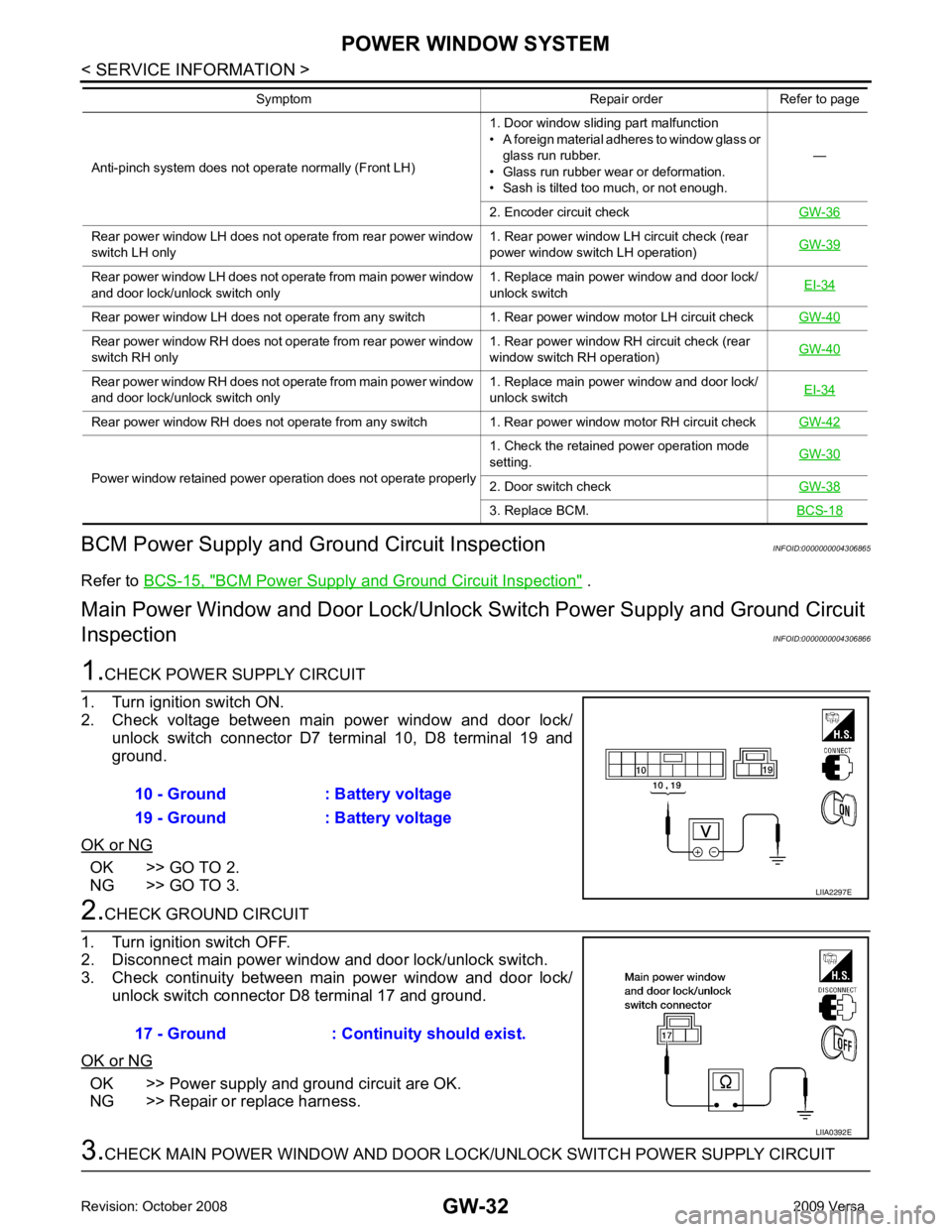
Main Power Window and D oor Lock/Unlock Switch Power Supply and Ground Circuit
Inspection INFOID:0000000004306866OK >> GO TO 2.
NG >> GO TO 3. OK >> Power supply and ground circuit are OK.
NG >> Repair or replace harness. Rear power window LH does not operate from rear power window
switch LH only 1. Rear power window LH circuit check (rear
power window switch LH operation) GW-39Rear power window LH does not operate from main power window
and door lock/unlock switch only 1. Replace main power window and door lock/
unlock switch EI-34Rear power window LH does not operate from any switch 1. Rear power window motor LH circuit check
GW-40Rear power window RH does not operate from rear power window
switch RH only 1. Rear power window RH circuit check (rear
window switch RH operation) GW-40Rear power window RH does not operate from main power window
and door lock/unlock switch only 1. Replace main power window and door lock/
unlock switch EI-34Rear power window RH does not operate from any switch 1. Rear power window motor RH circuit check
GW-42Power window retained power operation does not operate properly
1. Check the retained power operation mode
setting. GW-30 2. Door switch check
GW-38 3. Replace BCM.
BCS-18Symptom Repair order Refer to page
Page 3336 of 4331
GW
N
O P
1. Turn ignition switch OFF.
2. Disconnect BCM and main power window and door lock/unlock
switch.
3. Check continuity between BCM connector and main power win-
dow and door lock/unlock switch connectors.
4. Check continuity between BCM and ground.
OK or NG OK >> GO TO 4.
NG >> Repair or replace harness. OK >> Check the condition of the harness and the connector.
NG >> Replace BCM. Refer to BCS-18, " Removal and Installa-
tion of BCM " .
Front Power Window Motor LH Circuit Inspection INFOID:0000000004306867OK >> GO TO 2.Connector
Terminal Connector
Terminal Continuity
A B
BCM: M20 68
Main power window and
door lock/unlock switch: D7 10 Yes
69 C
19
Main power window and
door lock/unlock switch:
D8 Yes
Connector Terminal
GroundContinuity
A
BCM: M20 68 No
69 No