2009 NISSAN TIIDA Power Window
[x] Cancel search: Power WindowPage 518 of 4331

BL
N
O P
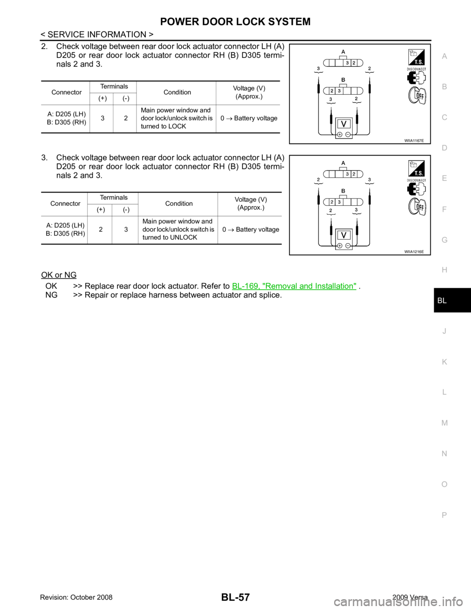
2. Check voltage between rear door lock actuator connector LH (A)
D205 or rear door lock actuator connector RH (B) D305 termi-
nals 2 and 3.
3. Check voltage between rear door lock actuator connector LH (A) D205 or rear door lock actuator connector RH (B) D305 termi-
nals 2 and 3.
OK or NG OK >> Replace rear door lock actuator. Refer to
BL-169, " Removal and Installation " .
NG >> Repair or replace harness between actuator and splice. Connector
Terminals
Condition Voltage (V)
(Approx.)
(+) (-)
A: D205 (LH)
B: D305 (RH) 3 2Main power window and
door lock/unlock switch is
turned to LOCK 0
→ Battery voltage
Page 530 of 4331

BL
N
O P
1: With Intelligent Key
2: Without Intelligent Key
3: Hatchback without Intelligent Key
4: Sedan without Intelligent Key
5: Hatchback
6: Sedan
7: With power door locks
8: With power windows
How to Perform Trouble Diagnosis INFOID:0000000004305012
1. Confirm the symptom or customer complaint.
2. Understand operation, description and function description. Refer to BL-58, " System Description " .
3. Perform the Preliminary Check. Refer to LT-11, " Preliminary Check " .
4. Check symptom and repair or replace the component.
5. Does the remote keyless entry system operate normally? If YES, GO TO 6. If NO, GO TO 4.
6. Inspection End.
Preliminary Check INFOID:0000000004305013
CHECK BCM CONFIGURATION Configuration " .
OK or NG OK >> Refer to
BL-71, " Work Flow " .
NG >> Change BCM configuration for "KEYLESS ENTRY" to "WITH". Refer to BCS-18, " Configuration " .
CONSULT-III Function (BCM) INFOID:0000000004305014
CONSULT-III can display each diagnostic item using the diagnostic test modes shown following. 65
7
SBAll door lock actuators
(lock) Output OFFOFF (neutral) 0V
ON (lock) Battery voltage
66 7
GFront door lock actua-
tor RH, rear door lock
actuators LH/RH (un-
lock) Output OFFOFF (neutral) 0V
ON (unlock) Battery voltage
67 B Ground Input ON — 0V
68 8
LPower window power
supply (RAP) Output —Ignition switch ON Battery voltage
Within 45 seconds after igni-
tion switch OFF Battery voltage
More than 45 seconds after ig-
nition switch OFF 0V
When front door LH or RH is
open or power window timer
operates 0V
69 8
P Battery power supply
OutputOFF
— Battery voltage
70 Y Battery power supply Input OFF — Battery voltage
Terminal
Wire
color Signal name Signal
input/
output Measuring condition
Reference value or waveform
(Approx.)
Ignition
switch Operation or condition
Page 576 of 4331

BL
N
O P
1: With Intelligent Key
2: Without Intelligent Key
3: Hatchback without Intelligent Key
4: Sedan without Intelligent Key
5: Hatchback
6: Sedan
7: With power door locks
8: With power windows
Trouble Diagnosis Procedure INFOID:0000000004305041
PRELIMINARY CHECK Configuration " .
OK or NG OK >> GO TO 3
NG >> Change BCM configuration for "I-KEY" to "WITH". Refer to BCS-18, " Configuration " .
Intelligent Key Battery Replacement " .
The engine cannot be started by all Intelligent Keys >> GO TO 4 65
7
SBAll door lock actuators
(lock) Output OFFOFF (neutral) 0V
ON (lock) Battery voltage
66 7
GFront door lock actua-
tor RH, rear door lock
actuators LH/RH (un-
lock) Output OFFOFF (neutral) 0V
ON (unlock) Battery voltage
67 B Ground Input ON — 0V
68 8
LPower window power
supply (RAP) Output —Ignition switch ON Battery voltage
Within 45 seconds after igni-
tion switch OFF Battery voltage
More than 45 seconds after ig-
nition switch OFF 0V
When front door LH or RH is
open or power window timer
operates 0V
69 8
P Battery power supply
OutputOFF
— Battery voltage
70 Y Battery power supply Input OFF — Battery voltage
Terminal
Wire
color Signal name Signal
input/
output Measuring condition
Reference value or waveform
(Approx.)
Ignition
switch Operation or condition
Page 640 of 4331

BL
N
O P
1: With Intelligent Key
2: Without Intelligent Key
3: Hatchback without Intelligent Key
4: Sedan without Intelligent Key
5: Hatchback
6: Sedan
7: With power door locks
8: With power windows
Terminal and Reference Valu e for Intelligent Key Unit INFOID:0000000004678879
65
7
SBAll door lock actuators
(lock) Output OFFOFF (neutral) 0V
ON (lock) Battery voltage
66 7
GFront door lock actua-
tor RH, rear door lock
actuators LH/RH (un-
lock) Output OFFOFF (neutral) 0V
ON (unlock) Battery voltage
67 B Ground Input ON — 0V
68 8
LPower window power
supply (RAP) Output —Ignition switch ON Battery voltage
Within 45 seconds after igni-
tion switch OFF Battery voltage
More than 45 seconds after ig-
nition switch OFF 0V
When front door LH or RH is
open or power window timer
operates 0V
69 8
P Battery power supply
OutputOFF
— Battery voltage
70 Y Battery power supply Input OFF — Battery voltage
Terminal
Wire
color Signal name Signal
input/
output Measuring condition
Reference value or waveform
(Approx.)
Ignition
switch Operation or condition Terminal
Wire
Color Item Condition
Voltage (V)Approx.
Ignition
Switch
Position Operation or Conditions
1 R Steering lock solenoid
power supply LOCK — 5
2 L CAN-H — — —
3 P CAN-L — — —
4 O Intelligent Key warning
buzzer LOCKOperate door request
switch. Buzzer OFF Battery voltage
Sound buzzer 0
5 G Front door request
switch LH —Press door request switch (driver side). 0
Other than above 5
6 Y Ignition switch (ON) ON — Battery voltage
7 LG Key switch LOCK Insert mechanical key into ignition switch. Battery voltage
Remove mechanical key from ignition
switch. 0
10 *1
WCVT or A/T device
(park position switch) ONShift lever in park position. 0
Other than above Battery voltage
11 SB Power source (Fus e) — — Battery voltage
12 B Ground — — 0
Page 643 of 4331

System Description " .
3. Repair or replace any malfunctioning parts. Refer to BL-182, " Trouble Diagnosis Chart by Symptom " .
4. Does back door opener operate normally? If Yes, GO TO 5. If No, GO TO 3.
5. Inspection End.
Trouble Diagnosis Chart by Symptom INFOID:0000000004305090
BCM Power Supply and Gr ound Circuit Inspection INFOID:0000000004678881Test item Content
TRUNK/BACK DOOR This test is able to check back door lock assembly (actuator) unlock operation.
Actuator opens back door lock assembly when “OPEN” on CONSULT-III screen is touched. Symptom Diagnoses/service procedure
Reference
page
Back door opener does not operate.
(Without Intelligent Key or power windows) 1. Check BCM power supply and ground circuit.
BCS-15 2. Check back door opener switch circuit.
BL-183 3. Check back door lock assembly (actuator) circuit.
BL-190 4. Replace BCM.
BCS-18Back door opener does not operate.
(Without Intelligent Key, with power windows) 1. Check BCM power supply and ground circuit.
BCS-15 2. Check back door opener switch circuit.
BL-186 3. Check back door lock assembly (actuator) circuit.
BL-190 4. Replace BCM.
BCS-18Back door opener does not operate.
(With Intelligent Key) 1. Check BCM power supply and ground circuit.
BCS-15 2.
Check Intelligent Key power supply and ground cir-
cuit. BL-126 3. Check back door opener switch circuit.
BL-188 4. Check back door lock assembly (actuator) circuit.
BL-190 5. Replace BCM.
BCS-18
Page 644 of 4331

BACK DOOR LOCK
BL-183
< SERVICE INFORMATION >
C
D E
F
G H
J
K L
M A
B BL
N
O P
OK >> GO TO 2.
NG >> If fuse is blown, be sure to eliminate caus e of malfunction before installing new fuse. Refer to PG-3, " Schematic " .
2.
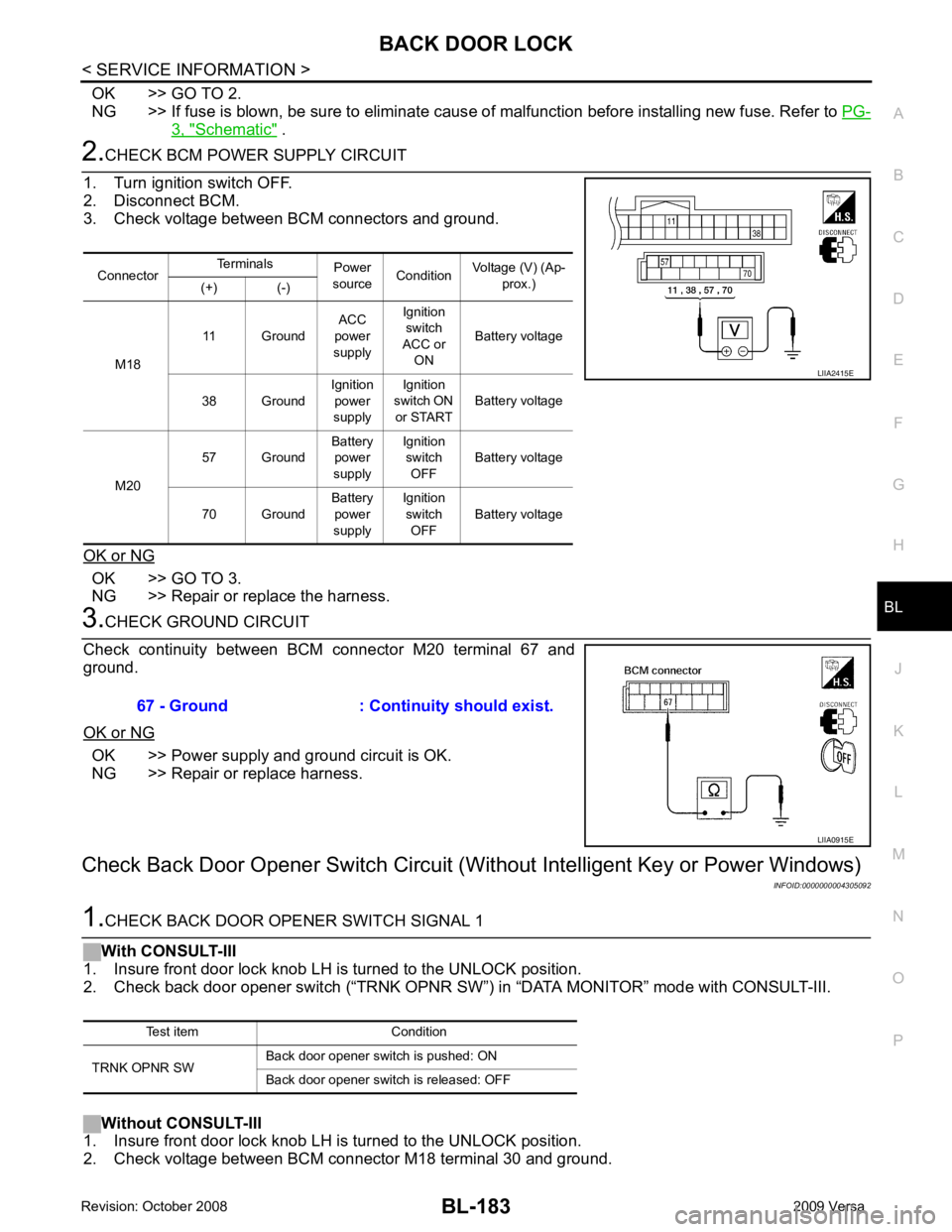
CHECK BCM POWER SUPPLY CIRCUIT
1. Turn ignition switch OFF.
2. Disconnect BCM.
3. Check voltage between BCM connectors and ground.
OK or NG OK >> GO TO 3.
NG >> Repair or replace the harness. 3.
CHECK GROUND CIRCUIT
Check continuity between BCM connector M20 terminal 67 and
ground.
OK or NG OK >> Power supply and ground circuit is OK.
NG >> Repair or replace harness.
Check Back Door Opener S witch Circuit (Without Intellig ent Key or Power Windows)
INFOID:00000000043050921.
CHECK BACK DOOR OPENER SWITCH SIGNAL 1
With CONSULT-III
1. Insure front door lock knob LH is turned to the UNLOCK position.
2. Check back door opener switch (“TRNK OPNR SW ”) in “DATA MONITOR” mode with CONSULT-III.
Without CONSULT-III
1. Insure front door lock knob LH is turned to the UNLOCK position.
2. Check voltage between BCM connector M18 terminal 30 and ground. Connector
Terminals
Power
source Condition Voltage (V) (Ap-
prox.)
(+) (-)
M18 11 Ground
ACC
power
supply Ignition
switch
ACC or ON Battery voltage
38 Ground Ignition
power
supply Ignition
switch ON
or START Battery voltage
M20 57 Ground
Battery
power
supply Ignition
switch OFF Battery voltage
70 Ground Battery
power
supply Ignition
switch OFF Battery voltage LIIA2415E
67 - Ground : Continuity should exist.
LIIA0915E
Test item Condition
TRNK OPNR SW Back door opener switch is pushed: ON
Back door opener switch is released: OFF
Page 647 of 4331

BL-186< SERVICE INFORMATION >
BACK DOOR LOCK
OK or NG OK >> Check the condition of harness and connector.
NG >> Replace BCM. Refer to BCS-18, " Removal and Installa-
tion of BCM " .
Check Back Door Opener Swit ch Circuit (Without Intelligent Key, with Power Windows)
INFOID:00000000043050931.
CHECK BACK DOOR OPENER SWITCH SIGNAL 1
With CONSULT-III
1. Insure front door lock knob RH is turned to the UNLOCK position.
2. Check back door opener switch (“TRNK OPNR SW”) in “DATA MONITOR” mode with CONSULT-III.
Without CONSULT-III
1. Insure front door lock knob RH is turned to the UNLOCK position.
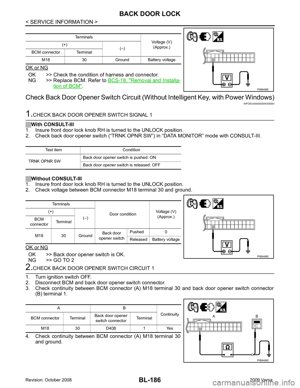
2. Check voltage between BCM connector M18 terminal 30 and ground.
OK or NG OK >> Back door opener switch is OK.
NG >> GO TO 2 2.
CHECK BACK DOOR OPENER SWITCH CIRCUIT 1
1. Turn ignition switch OFF.
2. Disconnect BCM and back door opener switch connector.
3. Check continuity between BCM connector (A) M 18 terminal 30 and back door opener switch connector
(B) terminal 1.
4. Check continuity between BCM connector (A) M18 terminal 30
and ground. Terminals
Voltage (V)
(Approx.)
(+)
(–)
BCM connector Terminal
M18 30 Ground Battery voltage PIIB6468E
Test item Condition
TRNK OPNR SW Back door opener switch is pushed: ON
Back door opener switch is released: OFF Terminals
Door conditionVoltage (V)
(Approx.)
(+)
(–)
BCM
connector Terminal
M18 30 Ground Back door
opener switch Pushed 0
Released Battery voltage PIIB6468E
A B
Continuity
BCM connector Terminal Back door opener
switch connector Terminal
M18 30 D408 1 Yes PIIB6469E
Page 664 of 4331

BL
N
O P
1: With Intelligent Key
2: Without Intelligent Key
3: Hatchback without Intelligent Key
4: Sedan without Intelligent Key
5: Hatchback
6: Sedan
7: With power door locks
8: With power windows
Terminal and Reference Valu e for Intelligent Key Unit INFOID:0000000004678894
65
7
SBAll door lock actuators
(lock) Output OFFOFF (neutral) 0V
ON (lock) Battery voltage
66 7
GFront door lock actua-
tor RH, rear door lock
actuators LH/RH (un-
lock) Output OFFOFF (neutral) 0V
ON (unlock) Battery voltage
67 B Ground Input ON — 0V
68 8
LPower window power
supply (RAP) Output —Ignition switch ON Battery voltage
Within 45 seconds after igni-
tion switch OFF Battery voltage
More than 45 seconds after ig-
nition switch OFF 0V
When front door LH or RH is
open or power window timer
operates 0V
69 8
P Battery power supply
OutputOFF
— Battery voltage
70 Y Battery power supply Input OFF — Battery voltage
Terminal
Wire
color Signal name Signal
input/
output Measuring condition
Reference value or waveform
(Approx.)
Ignition
switch Operation or condition Terminal
Wire
Color Item Condition
Voltage (V)Approx.
Ignition
Switch
Position Operation or Conditions
1 R Steering lock solenoid
power supply LOCK — 5
2 L CAN-H — — —
3 P CAN-L — — —
4 O Intelligent Key warning
buzzer LOCKOperate door request
switch. Buzzer OFF Battery voltage
Sound buzzer 0
5 G Front door request
switch LH —Press door request switch (driver side). 0
Other than above 5
6 Y Ignition switch (ON) ON — Battery voltage
7 LG Key switch LOCK Insert mechanical key into ignition switch. Battery voltage
Remove mechanical key from ignition
switch. 0
10 *1
WCVT or A/T device
(park position switch) ONShift lever in park position. 0
Other than above Battery voltage
11 SB Power source (Fus e) — — Battery voltage
12 B Ground — — 0