2009 NISSAN TIIDA engine control system
[x] Cancel search: engine control systemPage 3944 of 4331

MTC
N
O P
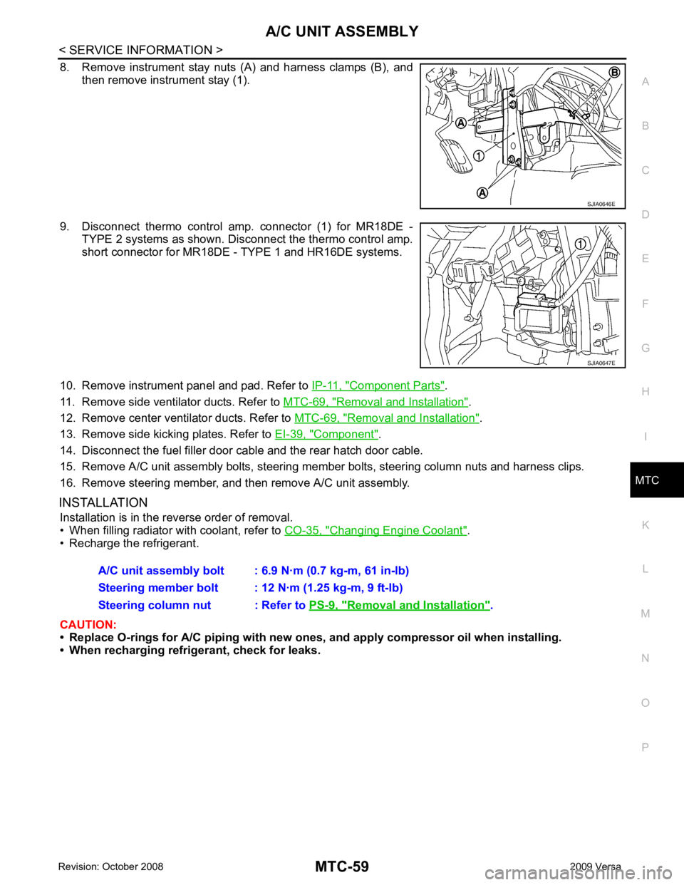
8. Remove instrument stay nuts (A) and harness clamps (B), and
then remove instrument stay (1).
9. Disconnect thermo control amp. connector (1) for MR18DE - TYPE 2 systems as shown. Disconnect the thermo control amp.
short connector for MR18DE - TYPE 1 and HR16DE systems.
10. Remove instrument panel and pad. Refer to IP-11, " Component Parts " .
11. Remove side ventilator ducts. Refer to MTC-69, " Removal and Installation " .
12. Remove center ventilator ducts. Refer to MTC-69, " Removal and Installation " .
13. Remove side kicking plates. Refer to EI-39, " Component " .
14. Disconnect the fuel filler door cable and the rear hatch door cable.
15. Remove A/C unit assembly bolts, steering member bolts, steering column nuts and harness clips.
16. Remove steering member, and then remove A/C unit assembly.
INSTALLATION Installation is in the reverse order of removal.
• When filling radiator with coolant, refer to CO-35, " Changing Engine Coolant " .
• Recharge the refrigerant.
CAUTION:
• Replace O-rings for A/C piping with new on es, and apply compressor oil when installing.
• When recharging refrigerant, check for leaks. Removal and Installation " .
Page 3974 of 4331

MTC
N
O P
Check all around the service valves. Ensure service valve caps are secured on the service valves (to
prevent leaks).
NOTE:
After removing A/C manifold gauge set from service va lves, wipe any residue from valves to prevent any
false readings by leak detector.
• Cooling unit (Evaporator)
With engine OFF, turn blower fan on “High” for at least 15 seconds to dissipate any refrigerant trace in
the cooling unit. Wait a minimum of 10 minutes ac cumulation time (refer to the manufacturer’s recom-
mended procedure for actual wait time) before inserting the leak detector probe into the drain hose.
Keep the probe inserted for at least 10 seconds. Use c aution not to contaminate the probe tip with water
or dirt that may be in the drain hose.
5. If a leak detector detects a leak, verify at least once by blowing compressed air into area of suspected
leak, then repeat check as outlined above.
6. Do not stop when one leak is found. Continue to check for additional leaks at all system components.
If no leaks are found, perform steps 7-10.
7. Start engine.
8. Set the heater A/C control as follows;
a. A/C switch: ON
b. Mode control dial position: VENT (Ventilation)
c. Intake door lever position: Recirculation
d. Max. cold temperature
e. Fan speed: High
9. Run engine at 1,500 rpm for at least 2 minutes.
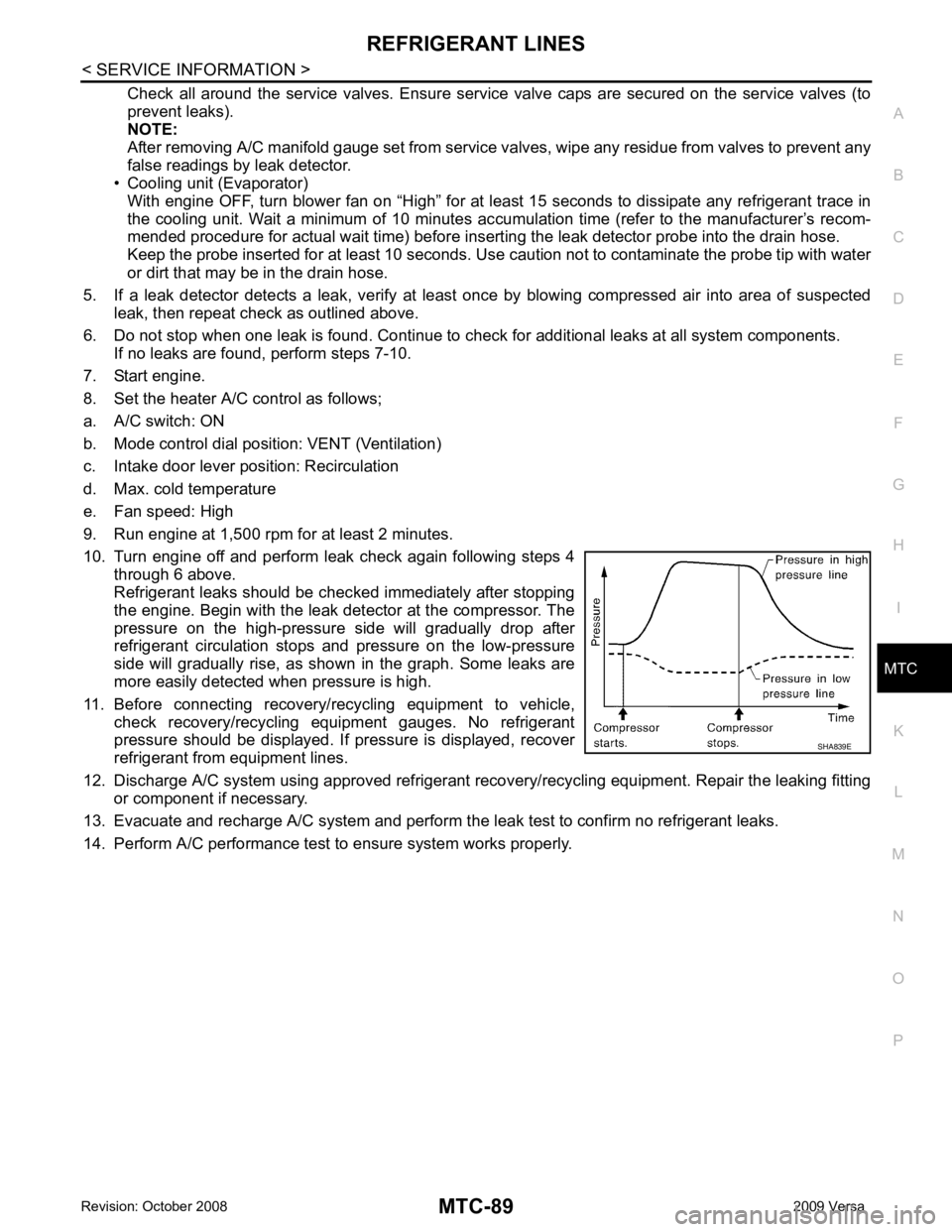
10. Turn engine off and perform leak check again following steps 4 through 6 above.
Refrigerant leaks should be chec ked immediately after stopping
the engine. Begin with the leak detector at the compressor. The
pressure on the high-pressure side will gradually drop after
refrigerant circulation stops and pressure on the low-pressure
side will gradually rise, as shown in the graph. Some leaks are
more easily detected when pressure is high.
11. Before connecting recovery/recycling equipment to vehicle, check recovery/recycling equipment gauges. No refrigerant
pressure should be displayed. If pressure is displayed, recover
refrigerant from equipment lines.
12. Discharge A/C system using approved refrigerant reco very/recycling equipment. Repair the leaking fitting
or component if necessary.
13. Evacuate and recharge A/C system and perform the l eak test to confirm no refrigerant leaks.
14. Perform A/C performance test to ensure system works properly.
Page 4008 of 4331

PG
N
O P
24 Y Cooling fan relay-3 Output —
Conditions correct for cooling
fan high operation Battery voltage
Conditions not correct for
cooling fan high operation 0V
26 O Tail lamp relay (park-
ing lamps) Output — Lighting switch in 2nd position Battery voltage
27 BR Tail lamp relay (park-
ing lamps) Output — Lighting switch in 2nd position Battery voltage
28 GR Tail lamp relay (park-
ing lamps) Output — Lighting switch in 2nd position Battery voltage
29 P Tail lamp relay (park-
ing lamps) Output — Lighting switch in 2nd position Battery voltage
30
(A/T
only) R Fuse 54 Output — Ignition switch ON or START Battery voltage
Ignition switch OFF or ACC 0V
31 O Fuse 55 Output — Ignition switch ON or START Battery voltage
Ignition switch OFF or ACC 0V
32 L Wiper high speed sig-
nal OutputON or
START Wiper switch OFF, LO, INT 0V
HI Battery voltage
33 Y Wiper low speed sig-
nal OutputON or
START Wiper switch OFF 0V
LO or INT Battery voltage
35 BR Starter relay (inhibit
switch) InputON or
START Selector lever in "P" or "N"
(CVT or A/T) or clutch pedal
depressed (M/T) Battery voltage
Selector lever any other posi-
tion (CVT or A/T) or clutch
pedal released (M/T) 0V
36 BR Fuel pump relay Output — Ignition switch ON or START Battery voltage
Ignition switch OFF or ACC 0V
37 G Oil pressure switch Input ON or
START Engine running and oil pres-
sure within specification Battery voltage
Engine not running or oil pres-
sure below specification 0V
38 R Wiper auto stop signal Input ON or
START Wipers not in park position Battery voltage
Wipers in park position 0V
39 B Ground Input — — 0V
40 P CAN-L — ON — —
41 L CAN-H — ON — —
45 R Horn relay control Input — Horn switch PUSHED, alarm
switch activated or door lock/
unlock is confirmed when op-
erating lock system via the
keyfob 0V
Horn switch released, alarm
not active, keyfob not active Battery voltage
46 Y Throttle control motor
relay control Input —Ignition switch ON or START 0V
Ignition switch OFF or ACC Battery voltage
47 GR Fuel pump relay con-
trol Input —Ignition switch ON or START 0V
Ignition switch OFF or ACC Battery voltage
Terminal
Wire
color Signal name Signal
input/
output Measuring condition
Reference value
(Approx.)
Ignition
switch Operation or condition
Page 4040 of 4331

PG
N
O P
Wiring Diagram Codes (Cell Codes)
INFOID:0000000004306667
Use the chart below to find out what each wiring diagram code stands for.
Refer to the wiring diagram code in the alphabetical index to find the location (page number) of each wiring
diagram. D4 D405 W/4 : Back door lock assembly C2 D413 B/1 : Rear window defogger (-)
D4 D406 W/2 : Back door request switch F3 D414 — : Body ground
E2 D407 W/2 : High mounted stop lamp Code Section Wiring Diagram Name
ABS BRC Anti-lock Brake System
A/C,M MTC Manual Air Conditioner
APPS1 EC Accelerator Pe dal Position Sensor
A/F EC Air Fuel Ratio Sensor 1
A/FH EC Air Fuel Ratio Sensor 1 Heater
APPS2 EC Accelerator Pe dal Position Sensor
APPS3 EC Accelerator Pe dal Position Sensor
ASC/BS EC ASCD Brake Switch
ASC/SW EC ASCD Steering Switch
ASCBOF EC ASCD Brake Switch
ASCIND EC ASCD Indicator
AT/IND DI A/T Indicator Lamp
AUDIO AV Audio
BACK/L LT Back-up Lamp
BA/FTS AT A/T Fluid Temperature Sensor and TCM Power Supply
B/DOOR BL Back Door Opener
BRK/SW EC Brake Switch
CAN AT CAN Communication Line
CAN CVT CAN Comm unication Line
CAN EC CAN Communication Line
CAN LAN CAN System
CHARGE SC Charging System
CHIME DI Warning Chime
COOL/F EC Cooling Fan Control
COMBSW LT Combination Switch
CVTIND DI CVT Indicator Lamp
D/LOCK BL Power Door Lock
DEF GW Rear Window Defogger
DTRL LT Headlamp - Wi th Daytime Light System
ECTS EC Engine Coolant Temperature Sensor
ENGSS AT Engine Speed Signal
EPS STC Electronic Controlled Power Steering
ETC1 EC Electric Throttle Control Function
ETC2 EC Throttle Control Motor Relay
ETC3 EC Throttle Control Motor
F/FOG LT Front Fog Lamp
F/PUMP EC Fuel Pump
FTS AT A/T Fluid Temperature Sensor
FTS CVT CVT Fluid Temperature Sensor Circuit
FTTS EC Fuel Tank Temperature Sensor
FUEL EC Fuel Ignition System Function
HEATER MTC Heater System
Page 4157 of 4331

SC
N
O P
CHARGING SYSTEM
System Description INFOID:0000000004306825
The generator provides DC voltage to operate the vehicl e's electrical system and to keep the battery charged.
The voltage output is controlled by the IC regulator.
Power is supplied at all times to generator terminal 3 through
• 10A fuse (No. 29, located in the fuse and fusible link box).
Power is supplied through terminal 1 to charge the batte ry and operate the vehicle's electrical system. Output
voltage is monitored at terminal 3 by the IC regulator. The charging circuit is protected by the 120A fusible link
[letter a , located in the fusible link box (battery)].
Ground is supplied
• to generator terminal 5
• through body ground F5, and
• through the generator case to the cylinder block
With the ignition switch in the ON or START position, power is supplied
• through 10A fuse [No. 3, located in the fuse block (J/B)]
• to combination meter terminal 28 for the charge warning lamp.
The IC regulator controls ground to terminal 38 of the combination meter through terminal 2 of the generator.
When the ignition is turned on and power becomes availabl e at terminal 2, this "wakes up" the regulator. The
regulator monitors charge output and grounds terminal 2 or leaves it open depending on charge output. With
power and ground supplied, the charge warning lamp will il luminate. When the generator is providing sufficient
voltage, the ground is opened and the charge warning lamp will go off.
If the charge warning lamp illuminates with the engine running, a malfunction is indicated.
Page 4252 of 4331
![NISSAN TIIDA 2009 Service Repair Manual DTC C1601
BATTERY VOLT "
TORQUE SENSOR
[C1604] When the torque sensor malfunction assembled in steering column
assembly is detected. STC-15, " DTC C1604
TORQUE SENSOR "
EPS MOTOR
[C1606] When the NISSAN TIIDA 2009 Service Repair Manual DTC C1601
BATTERY VOLT "
TORQUE SENSOR
[C1604] When the torque sensor malfunction assembled in steering column
assembly is detected. STC-15, " DTC C1604
TORQUE SENSOR "
EPS MOTOR
[C1606] When the](/manual-img/5/57398/w960_57398-4251.png)
DTC C1601
BATTERY VOLT "
TORQUE SENSOR
[C1604] When the torque sensor malfunction assembled in steering column
assembly is detected. STC-15, " DTC C1604
TORQUE SENSOR "
EPS MOTOR
[C1606] When the motor driver
malfunction of EPS control unit or EPS motor
malfunction is detected. STC-16, " DTC C1606
EPS MOTOR "
EEPROM
[C1607] When the memory (EEPROM) system malfunction is detected in
EPS control unit. STC-17, " DTC C1607
EEPROM "
CONTROL UNIT
[C1608] When the internal malfunction is detected in EPS control unit. STC-17, " DTC C1608
CONTROL UNIT "
CAN VHCL SPEED
[C1609] When the malfunction is detected in vehicle speed signal received
with CAN communication. STC-18, " DTC C1609
CAN VHCL SPEED "
CAN ENG RPM
[C1610] When the malfunction is detected in engine status signal received
with CAN communication. STC-19, " DTC C1610
CAN ENG RPM "
CAN COMM CIRCUIT
[U1000] When EPS control unit is
not transmitting or receiving CAN commu-
nication signal 2 seconds or more. STC-19, " DTC U1000
CAN COMM CIRCUIT "
NO DTC IS DETECTED.
FURTHER TESTING MAY BE RE-
QUIRED. No NG item has been detected. —Monitor item (Unit) Remarks
MOTOR VOL (V) Power supply voltage for EPS control unit is displayed
TORQUE SENSOR (Nm) Steering wheel turning force detected by torque sensor is displayed
MOTOR SIG (A) Current commanded value to EPS motor is displayed
MOTOR CURRENT (A) Current value cons umed by EPS motor is displayed
VEHICLE SPEED (km/h) or (mph) Vehicle speed is displayed from vehicle speed signal with CAN communication
WARNING LAMP (ON/OFF) EPS warning la mp control status is displayed
DERATING STAT (ON/OFF) Protect overload status is displayed
ENGINE STATUS (STOP/RUN) Engine spee d is displayed from engine status signal with CAN communication
Page 4259 of 4331

STC
N
O P
OK >>
INSPECTION END
NG >> Perform self-diagnosis with ABS actuator and el ectric unit (control unit) and combination meter.
Refer to BRC-18, " CONSULT-III Function (ABS) " ,
DI-12, " CONSULT-III Function (METER/M&A) "
.
DTC C1610 CAN ENG RPM INFOID:0000000004307304
CONSULT-III REFERENCE VALUE IN DATA MONITOR MODE Data are reference value.
DIAGNOSTIC PROCEDURE CONSULT-III Function (ENGINE) " (MR TYPE 1),
EC-1116, " CONSULT-III F
unction (ENGINE) " (MR TYPE 2) or
EC-103, " CONSULT-III Function " (HR16DE).
Is any malfunction detected by self-diagnosis? YES >> Check the malfunctioning system.
NO >> GO TO 2. EPS Control Unit Input/Output Signal Reference
Value " .
OK or NG OK >> GO TO 3.
NG >> Check EPS control unit pin terminals for damage or loose connection with harness connector. If
any items are damaged, repair or replace damaged parts. OK >>
INSPECTION END
NG >> Perform self-diagnosis with ECM again. Refer EC-604, " CONSULT-III Function (ENGINE) " (MR
TYPE 1), EC-1116, " CONSULT-III Function (ENGINE) " (MR TYPE 2) or
EC-103, " CONSULT-III
Function " (HR16DE).
DTC U1000 CAN COMM CIRCUIT INFOID:0000000004307305
DIAGNOSTIC PROCEDURE “ CAN COMM CIRCUIT [U1000] ” displayed?
YES >> Print out CONSULT-III screen and go to
LAN-17, " Trouble Diagnosis Flow Chart " .
NO >> INSPECTION END
Component Inspection INFOID:0000000004307306
EPS MOTOR 1. Turn ignition switch “OFF”.
2. Disconnect EPS control unit harness connector. Monitor item (Unit) Content Condition Display value
ENGINE STATUS (RUN/STOP) Engine status Engine stopped (Engine speed: Less than 400 rpm) STOP
Engine running (Engine speed: 400 rpm or more) RUN
Page 4261 of 4331
![NISSAN TIIDA 2009 Service Repair Manual TROUBLE DIAGNOSIS FOR SYMPTOMS
STC-21
< SERVICE INFORMATION >
[EPS] C
D E
F
H I
J
K L
M A
B STC
N
O
P
TROUBLE DIAGNOSIS FOR SYMPTOMS
EPS Warning Lamp Does Not Turn ON INFOID:0000000004307307
SYMPTOM: NISSAN TIIDA 2009 Service Repair Manual TROUBLE DIAGNOSIS FOR SYMPTOMS
STC-21
< SERVICE INFORMATION >
[EPS] C
D E
F
H I
J
K L
M A
B STC
N
O
P
TROUBLE DIAGNOSIS FOR SYMPTOMS
EPS Warning Lamp Does Not Turn ON INFOID:0000000004307307
SYMPTOM:](/manual-img/5/57398/w960_57398-4260.png)
TROUBLE DIAGNOSIS FOR SYMPTOMS
STC-21
< SERVICE INFORMATION >
[EPS] C
D E
F
H I
J
K L
M A
B STC
N
O
P
TROUBLE DIAGNOSIS FOR SYMPTOMS
EPS Warning Lamp Does Not Turn ON INFOID:0000000004307307
SYMPTOM: EPS warning lamp does not turn ON when ignition switch to “ON”.
DIAGNOSTIC PROCEDURE 1.
CHECK SYSTEM FOR CAN COMMUNICATION LINE
Perform self-diagnosis. Refer to STC-11, " CONSULT-III Function (EPS) " .
Is the “ CAN COMM CIRCUIT [U1000] ” displayed?
YES >> Perform trouble diagnosis for CAN communication line. Refer to
STC-19, " DTC U1000 CAN
COMM CIRCUIT " .
NO >> GO TO 2. 2.
CHECK EPS CONTROL UNIT
Check EPS control unit input/output signal. Refer to STC-9, " EPS Control Unit Input/Output Signal Reference
Value " .
OK or NG OK >> GO TO 3.
NG >> Check EPS control unit pin terminals for damage or loose connection with harness connector. If
any items are damaged, repair or replace damaged parts. 3.
SYMPTOM CHECK
Check again.
OK or NG OK >>
INSPECTION END
NG >> Replace combination meter. Refer to DI-19, " Removal and Installation " .
EPS Warning Lamp Does Not Turn OFF INFOID:0000000004307308
SYMPTOM: EPS warning lamp does not turn OFF for several seconds after starting the engine.
DIAGNOSTIC PROCEDURE 1.
CHECK SELF-DIAGNOSTIC RESULTS
Perform self-diagnosis. Refer to STC-11, " CONSULT-III Function (EPS) " .
Is any malfunction detected by self-diagnosis? YES >> Check the malfunctioning system.
NO >> GO TO 2. 2.
CHECK EPS CONTROL UNI T POWER SUPPLY CIRCUIT
1. Turn ignition switch “OFF”.
2. Disconnect EPS control unit harness connector.
3. Turn ignition switch “ON”. (Do not start engine.)
4. Check voltage between EPS control unit harness connector (A) terminals and ground.
Connector Terminal VoltageM53 10 – Ground Battery voltage
M54 17 – Ground Battery voltage SGIA1626E