2009 NISSAN TIIDA engine control system
[x] Cancel search: engine control systemPage 3732 of 4331
LU
NP
O
SERVICE INFORMATION
PRECAUTIONS
Precaution for Supplemental Restraint System (SRS) "AIR BAG" and "SEAT BELT
PRE-TENSIONER" INFOID:0000000004784384
The Supplemental Restraint System such as “A IR BAG” and “SEAT BELT PRE-TENSIONER”, used along
with a front seat belt, helps to reduce the risk or severi ty of injury to the driver and front passenger for certain
types of collision. This system includes seat belt switch inputs and dual stage front air bag modules. The SRS
system uses the seat belt switches to determine the front air bag deployment, and may only deploy one front
air bag, depending on the severity of a collision and w hether the front occupants are belted or unbelted.
Information necessary to service the system safely is included in the SRS and SB section of this Service Man-
ual.
WARNING:
• To avoid rendering the SRS inoper ative, which could increase the risk of personal injury or death in
the event of a collision which would result in air bag inflation, all maintenance must be performed by
an authorized NISSAN/INFINITI dealer.
• Improper maintenance, including in correct removal and installation of the SRS can lead to personal
injury caused by unintentional act ivation of the system. For removal of Spiral Cable and Air Bag
Module, see the SRS section.
• Do not use electrical test equipm ent on any circuit related to the SRS unless instructed to in this
Service Manual. SRS wiring harnesses can be identi fied by yellow and/or orange harnesses or har-
ness connectors.
• When working near the Airbag Diagnosis Sensor Un it or other Airbag System sensors with the Igni-
tion ON or engine running, DO NOT use air or el ectric power tools or strike near the sensor(s) with a
hammer. Heavy vibration could activate the sensor( s) and deploy the air bag(s), possibly causing
serious injury.
• When using air or electric power tools or hammers , always switch the Ignition OFF, disconnect the
battery, and wait at least 3 minutes before performing any service.
Precaution Necessary for Steering Wh eel Rotation After Battery Disconnect
INFOID:0000000004673030
NOTE:
• This Procedure is applied only to models with Inte lligent Key system and NATS (NISSAN ANTI-THEFT SYS-
TEM).
• Remove and install all control units after disconnecti ng both battery cables with the ignition knob in the
″ LOCK ″ position.
• Always use CONSULT-III to perform self-diagnosis as a part of each function inspection after finishing work.
If DTC is detected, perform trouble diagnosis according to self-diagnostic results.
For models equipped with the Intelligent Key system and NATS , an electrically controlled steering lock mech-
anism is adopted on the key cylinder.
For this reason, if the battery is disconnected or if the battery is discharged, the steering wheel will lock and
steering wheel rotation will become impossible.
If steering wheel rotation is required when battery pow er is interrupted, follow the procedure below before
starting the repair operation.
OPERATION PROCEDURE 1. Connect both battery cables. NOTE:
Supply power using jumper cables if battery is discharged.
2. Use the Intelligent Key or mechanical key to turn the ignition switch to the ″ACC ″ position. At this time, the
steering lock will be released.
3. Disconnect both battery cables. The steering lock will remain released and the steering wheel can be
rotated.
4. Perform the necessary repair operation.
5. When the repair work is completed, return the ignition switch to the ″LOCK ″ position before connecting
the battery cables. (At this time, the steering lock mechanism will engage.)
6. Perform a self-diagnosis check of al l control units using CONSULT-III.
Page 3746 of 4331
MA
N
O P
SERVICE INFORMATION
PRECAUTIONS
Precaution for Supplemental Restraint System (SRS) "AIR BAG" and "SEAT BELT
PRE-TENSIONER" INFOID:0000000004803408
The Supplemental Restraint System such as “A IR BAG” and “SEAT BELT PRE-TENSIONER”, used along
with a front seat belt, helps to reduce the risk or severi ty of injury to the driver and front passenger for certain
types of collision. This system includes seat belt switch inputs and dual stage front air bag modules. The SRS
system uses the seat belt switches to determine the front air bag deployment, and may only deploy one front
air bag, depending on the severity of a collision and w hether the front occupants are belted or unbelted.
Information necessary to service the system safely is included in the SRS and SB section of this Service Man-
ual.
WARNING:
• To avoid rendering the SRS inoper ative, which could increase the risk of personal injury or death in
the event of a collision which would result in air bag inflation, all maintenance must be performed by
an authorized NISSAN/INFINITI dealer.
• Improper maintenance, including in correct removal and installation of the SRS can lead to personal
injury caused by unintentional act ivation of the system. For removal of Spiral Cable and Air Bag
Module, see the SRS section.
• Do not use electrical test equipm ent on any circuit related to the SRS unless instructed to in this
Service Manual. SRS wiring harnesses can be identi fied by yellow and/or orange harnesses or har-
ness connectors.
PRECAUTIONS WHEN USING POWER TOOLS (AIR OR ELECTRIC) AND HAMMERS WARNING:
• When working near the Airbag Diagnosis Sensor Un it or other Airbag System sensors with the Igni-
tion ON or engine running, DO NOT use air or el ectric power tools or strike near the sensor(s) with a
hammer. Heavy vibration could activate the sensor( s) and deploy the air bag(s), possibly causing
serious injury.
• When using air or electric power tools or hammers , always switch the Ignition OFF, disconnect the
battery, and wait at least 3 minutes before performing any service.
Precaution Necessary for Steering Wh eel Rotation After Battery Disconnect
INFOID:0000000004803409
NOTE:
• This Procedure is applied only to models with Inte lligent Key system and NATS (NISSAN ANTI-THEFT SYS-
TEM).
• Remove and install all control units after disconnecti ng both battery cables with the ignition knob in the
″ LOCK ″ position.
• Always use CONSULT-III to perform self-diagnosis as a part of each function inspection after finishing work.
If DTC is detected, perform trouble diagnosis according to self-diagnostic results.
For models equipped with the Intelligent Key system and NATS , an electrically controlled steering lock mech-
anism is adopted on the key cylinder.
For this reason, if the battery is disconnected or if the battery is discharged, the steering wheel will lock and
steering wheel rotation will become impossible.
If steering wheel rotation is required when battery pow er is interrupted, follow the procedure below before
starting the repair operation.
OPERATION PROCEDURE 1. Connect both battery cables. NOTE:
Supply power using jumper cables if battery is discharged.
2. Use the Intelligent Key or mechanical key to turn the ignition switch to the ″ACC ″ position. At this time, the
steering lock will be released.
3. Disconnect both battery cables. The steering lock will remain released and the steering wheel can be
rotated.
4. Perform the necessary repair operation.
Page 3752 of 4331
MA
N
O P
PERIODIC MAINTENANCE
Introduction of Periodic Maintenance INFOID:0000000004305184
Two different maintenance schedules are provi ded, and should be used, depending upon the conditions in
which the vehicle is mainly operated. After 60,000 miles (96,000 km) or 48 months, continue the periodic
maintenance at the same mileage/time intervals.
Schedule 1 INFOID:0000000004305185
Emission Control System Maintenance Abbreviations: R = Replace. I = Inspect. Correct or r eplace if necessary. [ ]: At the mileage intervals only
Schedule 1
Follow Periodic Maintenance Schedule 1 if your driving habits frequently includes
one or more of the following driving conditions:
• Repeated short trips of less than 5 miles (8 km).
• Repeated short trips of less than 10 miles (16 km) with outside temperatures re- maining below freezing.
• Operating in hot weather in stop-and-go “rush hour” traffic.
• Extensive idling and/or low speed driving for long distances, such as police, taxi or door-to-door delivery use.
• Driving in dusty conditions.
• Driving on rough, muddy, or salt spread roads.
• Towing a trailer, using a camper or a car-top carrier. Emission Control Sys-
tem Maintenance MA-9 Chassis and Body
Maintenance
MA-9Schedule 2
Follow Periodic Maintenance Schedule 2 if none of the driving conditions shown
in Schedule 1 apply to your driving habits. Emission Control Sys-
tem Maintenance MA-11 Chassis and Body
Maintenance MA-11 (HR)
MA-26 (MR)
Air cleaner filter NOTE (2) [R]MA-20 (HR)
MA-29 (MR)
EVAP vapor lines I*MA-25 (HR)
MA-36 (MR)
Fuel lines I*MA-29 Fuel filter NOTE (3)
—
Engine coolant NOTE (4) MA-17 (HR)
MA-26 (MR)
Engine oil R R R R R R R R MA-20 (HR)
MA-30 (MR)
Engine oil filter (Use
genuine oil filter or
equivalent) R R R R R R R R
MA-23 (HR)
MA-33 (MR)
Spark plugs (Iridium-
tipped type) Replace every 105,000 miles (169,000 km)
MA-24 (HR)
MA-34 (MR)
Intake and exhaust
valve clearance* NOTE (5) EM-119, " Cylinder
Head " (HR)
EM-227, " Standard
and Limit " (MR)
Page 3761 of 4331
MA-18< SERVICE INFORMATION >
ENGINE MAINTENANCE (HR16DE)
1. Open radiator drain plug (1) at the bottom of radiator, and then remove radiator cap.
• Front
When draining all of engine coolant in the system, open
water drain plug on cylinder block. Refer to EM-96 .
CAUTION:
• Perform this step when engine is cold.
• Do not spill engine coolant on drive belt.
2. Remove reservoir tank as necessary, and drain engine coolant and clean reservoir tank before installing. Refer to CO-16, " Component " .
3. Check drained engine coolant for contaminants such as rust, corrosion or discoloration. If contaminated, flush the engine cooling system.
REFILLING ENGINE COOLANT
1. Install the radiator drain plug. Install the reservoir tank and cylinder block drain plug, if removed for a total
system drain or for engine removal or repair.
• The radiator must be complete ly empty of coolant and water.
• Apply sealant to the threads of the cylinder bl ock drain plugs. Use Genuine High Performance
Thread Sealant or equivalent. Refer to GI-42, " Recommended Chemical Product and Sealant " .
2. If disconnected, reattach the upper radiator hose at the engine side.
3. Set the vehicle heater controls to the full HOT and heat er ON position. Turn the vehicle ignition ON with
the engine OFF as necessary to activate the heater mode.
4. Install the Tool by installing the radiator cap adapter onto the radiator neck opening. Then attach the gauge body assembly
with the refill tube and the venturi assembly to the radiator cap
adapter.
5. Insert the refill hose into the coolant mixture container that is placed at floor level. Make sure the ball valve is in the closed
position.
• Use Genuine NISSAN Long Life Anti-freeze coolant or
equivalent, mixed with distil led water or demineralized
water.
Refer to MA-15, " Anti-freeze Coolant Mixture Ratio " .
6. Install an air hose to the venturi assembly, the air pressure must be within specification.
CAUTION:
The compressed air supply must be equipped with an air dryer.
7. The vacuum gauge will begin to rise and there will be an audible hissing noise. During this process open the ball valve on the refill hose slightly. Coolant will be vi sible rising in the refill hose. Once the refill hose is
full of coolant, close the ball valve. This will purge any air trapped in the refill hose. PBIC3799E
Radiator drain plug : Refer to
CO-16, " Component " .
Cylinder block drain plug : Refer to EM-96, " Disassembly and Assembly " .
Tool number : KV991J0070 (J-45695)
Engine coolant capacity
(with reservoir tank) : Refer to
MA-14, " Fluids
and Lubricants " .
Compressed air
supply pressure : 5.7 - 8.5 kPa (5.6 - 8.4 kg/cm
2
,
80 - 120 psi) LLIA0058E
Page 3770 of 4331
ENGINE MAINTENANCE (MR18DE)
MA-27
< SERVICE INFORMATION >
C
D E
F
G H
I
J
K
M A
B MA
N
O P
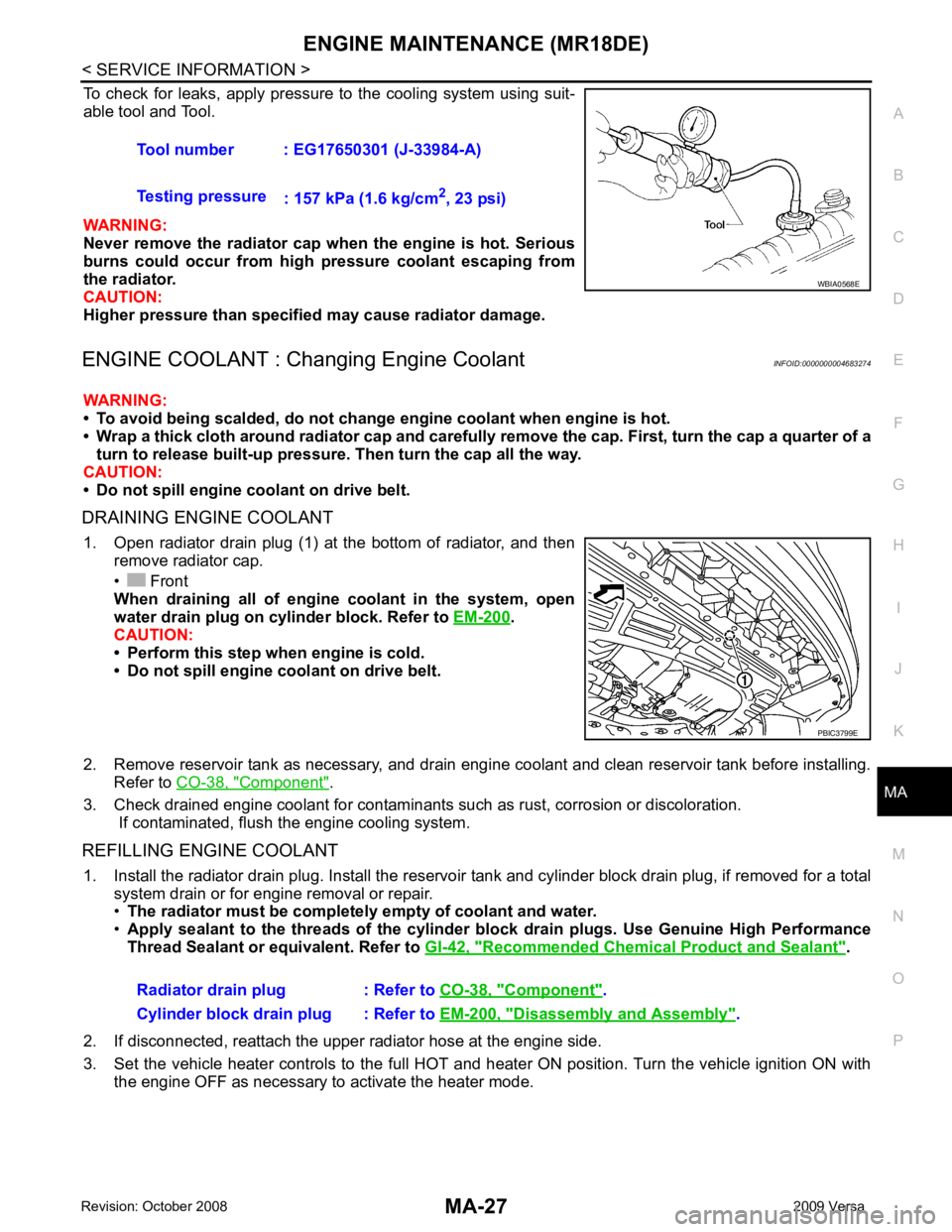
To check for leaks, apply pressure to the cooling system using suit-
able tool and Tool.
WARNING:
Never remove the radiator cap wh en the engine is hot. Serious
burns could occur from high pressure coolant escaping from
the radiator.
CAUTION:
Higher pressure than specified may cause radiator damage.
ENGINE COOLANT : Chang ing Engine Coolant INFOID:0000000004683274
WARNING:
• To avoid being scalded, do not change engine coolant when engine is hot.
• Wrap a thick cloth around radiator cap and carefully remove the cap. First, turn the cap a quarter of a
turn to release built-up pressure. Then turn the cap all the way.
CAUTION:
• Do not spill engine coolant on drive belt.
DRAINING ENGINE COOLANT 1. Open radiator drain plug (1) at the bottom of radiator, and then remove radiator cap.
• Front
When draining all of engine coolant in the system, open
water drain plug on cylinder block. Refer to EM-200 .
CAUTION:
• Perform this step when engine is cold.
• Do not spill engine coolant on drive belt.
2. Remove reservoir tank as necessary, and drain engi ne coolant and clean reservoir tank before installing.
Refer to CO-38, " Component " .
3. Check drained engine coolant for contaminants such as rust, corrosion or discoloration. If contaminated, flush the engine cooling system.
REFILLING ENGINE COOLANT 1. Install the radiator drain plug. Install the reservoir tank and cylinder block drain plug, if removed for a total
system drain or for engine removal or repair.
• The radiator must be complete ly empty of coolant and water.
• Apply sealant to the threads of the cylinder blo ck drain plugs. Use Genuine High Performance
Thread Sealant or equivalent. Refer to GI-42, " Recommended Chemical Product and Sealant " .
2. If disconnected, reattach the upper radiator hose at the engine side.
3. Set the vehicle heater controls to the full HOT and heat er ON position. Turn the vehicle ignition ON with
the engine OFF as necessary to activate the heater mode. Tool number : EG17650301 (J-33984-A)
Testing pressure : 157 kPa (1.6 kg/cm 2
, 23 psi) WBIA0568E
PBIC3799E
Radiator drain plug : Refer to
CO-38, " Component " .
Cylinder block drain plug : Refer to EM-200, " Disassembly and Assembly " .
Page 3811 of 4331
MT
N
O P
Installation is in the reverse order of removal.
CAUTION:
• Make sure the transaxle assembly does not interfer e with the wire harnesses and clutch tube.
• When installing transaxle assembly, do not bring input shaft into contact with clutch cover.
• If transaxle is removed from the vehicle, always replace CSC. Refer to CL-12, " Removal and Installa-
tion " .
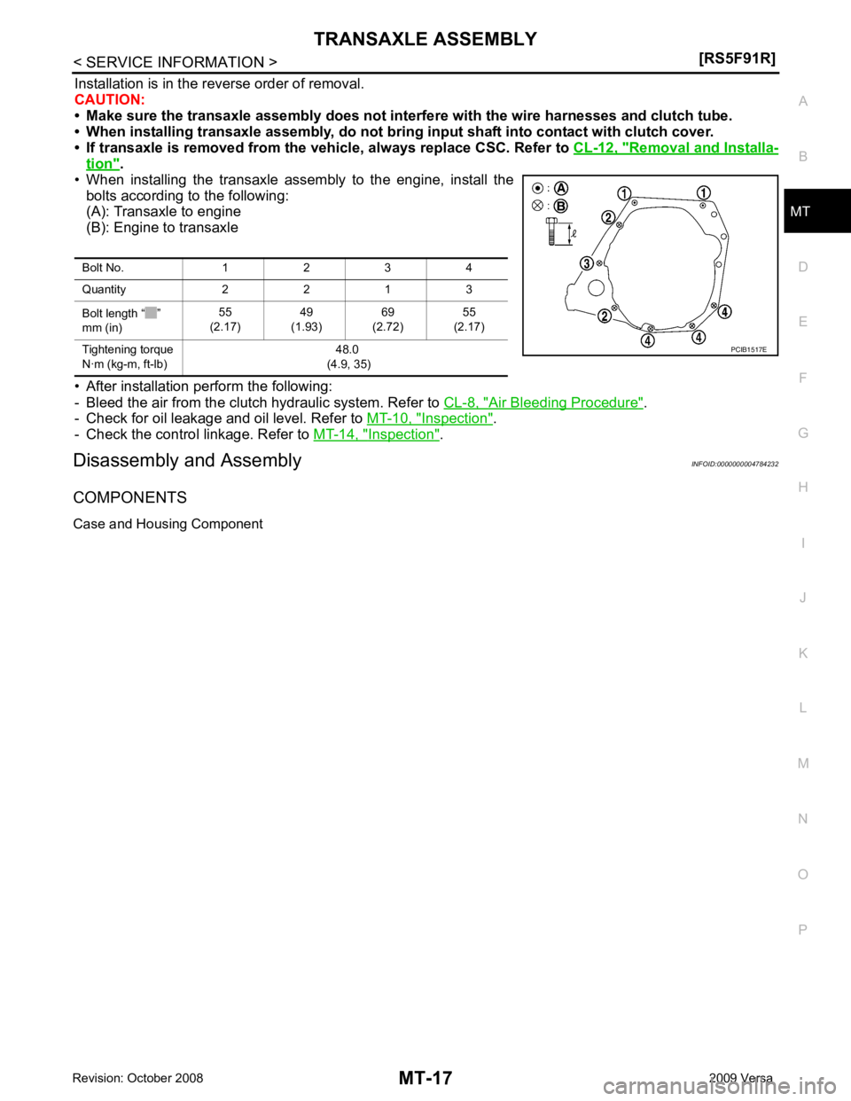
• When installing the transaxle assembly to the engine, install the bolts according to the following:
(A): Transaxle to engine
(B): Engine to transaxle
• After installation perform the following:
- Bleed the air from the clutch hydraulic system. Refer to CL-8, " Air Bleeding Procedure " .
- Check for oil leakage and oil level. Refer to MT-10, " Inspection " .
- Check the control linkage. Refer to MT-14, " Inspection " .
Disassembly and Assembly INFOID:0000000004784232
COMPONENTS
Case and Housing Component Bolt No. 1 2 3 4
Quantity 2 2 1 3
Bolt length “ ”
mm (in) 55
(2.17) 49
(1.93) 69
(2.72) 55
(2.17)
Tightening torque
N·m (kg-m, ft-lb) 48.0
(4.9, 35)
Page 3888 of 4331
MTC
N
O P
SERVICE INFORMATION
PRECAUTIONS
Precaution for Supplemental Restraint System (SRS) "AIR BAG" and "SEAT BELT
PRE-TENSIONER" INFOID:0000000004784399
The Supplemental Restraint System such as “A IR BAG” and “SEAT BELT PRE-TENSIONER”, used along
with a front seat belt, helps to reduce the risk or severi ty of injury to the driver and front passenger for certain
types of collision. This system includes seat belt switch inputs and dual stage front air bag modules. The SRS
system uses the seat belt switches to determine the front air bag deployment, and may only deploy one front
air bag, depending on the severity of a collision and w hether the front occupants are belted or unbelted.
Information necessary to service the system safely is included in the SRS and SB section of this Service Man-
ual.
WARNING:
• To avoid rendering the SRS inoper ative, which could increase the risk of personal injury or death in
the event of a collision which would result in air bag inflation, all maintenance must be performed by
an authorized NISSAN/INFINITI dealer.
• Improper maintenance, including in correct removal and installation of the SRS can lead to personal
injury caused by unintentional act ivation of the system. For removal of Spiral Cable and Air Bag
Module, see the SRS section.
• Do not use electrical test equipm ent on any circuit related to the SRS unless instructed to in this
Service Manual. SRS wiring harnesses can be identi fied by yellow and/or orange harnesses or har-
ness connectors.
PRECAUTIONS WHEN USING POWER TOOLS (AIR OR ELECTRIC) AND HAMMERS WARNING:
• When working near the Airbag Diagnosis Sensor Un it or other Airbag System sensors with the Igni-
tion ON or engine running, DO NOT use air or el ectric power tools or strike near the sensor(s) with a
hammer. Heavy vibration could activate the sensor( s) and deploy the air bag(s), possibly causing
serious injury.
• When using air or electric power tools or hammers , always switch the Ignition OFF, disconnect the
battery, and wait at least 3 minutes before performing any service.
Precaution Necessary for Steering Wh eel Rotation After Battery Disconnect
INFOID:0000000004687764
NOTE:
• This Procedure is applied only to models with Inte lligent Key system and NATS (NISSAN ANTI-THEFT SYS-
TEM).
• Remove and install all control units after disconnecti ng both battery cables with the ignition knob in the
″ LOCK ″ position.
• Always use CONSULT-III to perform self-diagnosis as a part of each function inspection after finishing work.
If DTC is detected, perform trouble diagnosis according to self-diagnostic results.
For models equipped with the Intelligent Key system and NATS , an electrically controlled steering lock mech-
anism is adopted on the key cylinder.
For this reason, if the battery is disconnected or if the battery is discharged, the steering wheel will lock and
steering wheel rotation will become impossible.
If steering wheel rotation is required when battery pow er is interrupted, follow the procedure below before
starting the repair operation.
OPERATION PROCEDURE 1. Connect both battery cables. NOTE:
Supply power using jumper cables if battery is discharged.
2. Use the Intelligent Key or mechanical key to turn the ignition switch to the ″ACC ″ position. At this time, the
steering lock will be released.
3. Disconnect both battery cables. The steering lock will remain released and the steering wheel can be
rotated.
4. Perform the necessary repair operation.
Page 3934 of 4331

MTC
N
O P
Testing must be performed as follows:
TEST READING Recirculating-to-discharge Air Temperature Table
Ambient Air Temperature-to-operating Pressure Table
*1: With blower control dial in the "1" position
*2: With blower control dial in the "4" position.
TROUBLE DIAGNOSIS FOR ABNORMAL PRESSURE Whenever system’s high and/or low side pressure(s) is /are abnormal, diagnose using a manifold gauge. The
marker above the gauge scale in the following tables indicates the standard (usual) pressure range. Since the
standard (usual) pressure, however, differs from vehicle to vehicle, refer to above table (Ambient air tempera-
ture-to-operating pressure table). Vehicle condition Indoors or in the shade (in a well-ventilated place)
Doors Closed
Door window Open
Hood Open
TEMP. Max. COLD
Mode control dial (Ventilation) set
Intake door lever (Recirculation) set
Blower speed Max. speed set
Engine speed Idle speed
Operate the air conditioning system for 10 minutes before taking measurements. Inside air (Recirculating air) at blower assembly inlet
Discharge air temperature at center ventilator
°C ( °F)
Relative humidity
% Air temperature
°C ( °F)
50 - 60 20 (68) 7.2 - 9.1 (45 - 48)
25 (77) 11.4 - 13.8 (53 - 57)
30 (86) 15.5 - 18.4 (60 - 65)
35 (95) 20.3 - 23.7 (69 - 75)
60 - 70 20 (68) 9.1 - 10.9 (48 - 52)
25 (77) 13.8 - 16.2 (57 - 61)
30 (86) 18.4 - 21.3 (65 - 70)
35 (95) 23.7 - 27.1 (75 - 81) Ambient air
High-pressure (Discharge side)
kPa (bar, kg/cm 2
, psi) Low-pressure (Suction side)
kPa (bar, kg/cm 2
, psi)
Relative humidity
% Air temperature
°C ( °F)
50 - 70 20 (68)
843 - 1,036 *1
(11.08 - 13.63, 8.6 - 10.6, 122 - 150) 159.0 - 194.0
(1.59 - 1.94, 1.62 - 1.98, 23.1 - 28.1)
25 (77) 1,094 - 1,338 *1
(10.94 - 13.38, 11.2 - 13.6, 159 - 194) 196.3 - 240.0
(1.96 - 2.40, 2.00 - 2.45, 28.5 - 34.8)
30 (86) 1,298 - 1,590 *1
(12.98 - 15.90, 13.2 - 16.2, 188 - 231) 248.0 - 302.7
(2.48 - 3.03, 2.53 - 3.09, 36.0 - 43.9)
35 (95) 1,383 - 1,688 *2
(13.83 - 16.88, 14.1 - 17.2, 201 - 245) 308.8 - 377.4
(3.09 - 3.77, 3.15 - 3.85, 44.8 - 54.7)
40 (104) 1,628 - 1,988 *2
(16.28 - 19.88, 16.6 - 20.3, 236 - 288) 377.4 - 461.2
(3.77 - 4.61, 3.85 - 4.70, 54.7 - 66.8)