2009 NISSAN TIIDA engine control system
[x] Cancel search: engine control systemPage 3288 of 4331

GI
N
O P
CONSULT-III CHECKING SYSTEM
Description INFOID:0000000004307366
• CONSULT-III is a hand-held type tester. When it is connected with a diagnostic connector equipped on the vehicle side, it will communicate with the contro l unit equipped in the vehicle and then enable various kinds
of diagnostic tests.
• Refer to CONSULT-III Operator's Manual for more information.
Function and System Application INFOID:0000000004307367
x: Applicable.
*1: If equipped.
*2: With automatic transmission (A/T).
*3: With continuously variable transmission (CVT).
*4: With security card installed. Diagnostic test mode FunctionENGINE
ABS* 1
AIR BAG EPS
IPDM E/R BCM
METER/M&A
INTELLIGENT KEY* 1
TRANSMISSION* 2
TRANSMISSION* 3
Work support This mode enables a technician to adjust some devices faster and
more accurately by following indications on CONSULT-III. x - - - - x - x x x
Self-diagnostic results Self-diagnostic results can be read and erased quickly. x x x x x x x x x x
Trouble diagnostic record Current self-diagnostic results and all trouble diagnostic records
previously stored can be read. - - x - - - - - - -
Data monitor Input/Output data in the ECU can be read. x x x x x x x x x x
CAN diagnostic support
monitor The communication condition of CAN communication line can be
read. x x - x x x x x x x
Calibration data* 2
Shows unit calibration IDs, offsets and gains. This data is stored in
the ECU memory. - - - - - - - - - x
Active test Diagnostic Test Mode in which CONSULT-III drives actuators apart
from ECU shifting some parameters in a specified range. x x - - x x - x - -
Function test This mode can show results of self-diagnosis of ECU with either
"OK" or "NG". For engines, more practical tests regarding sensors/
switches and/or actuators are available. x x x - - - - - x x
DTC & SRT confirmation The results of SRT (System Readiness Test) and the self-diagno-
sis status/result can be confirmed. x - - - - - - - x -
DTC work support The operating condition to confirm Diagnosis Trouble Codes can
be selected. x - - - - - - - x -
ECM/ECU part number ECM/ECU part number can be read. x x - x - x - x x x
ECU discriminated No. Classification number of a replacement ECU can be read to pre-
vent an incorrect ECU from being installed. - - x - - - - - - -
Passenger airbag Displays the STATUS (readiness) of front passenger air bag. - - x - - - - - - -
Configuration Sets control module parameters to match vehicle options. - - - - - x - - - -
Control unit initialization *4
All registered ignition key IDs in NATS components can be initial-
ized and new IDs can be registered. - - - - - x - - - -
PIN Read *4
This mode enables technician to get BCM-specific 5-digit code. - - - - - x - - - -
Page 3300 of 4331

GI
N
O P
TERMINOLOGY
SAE J1930 Terminology List INFOID:0000000004307379
All emission related terms used in this publication in accordance with SAE J1930 are listed. Accordingly, new
terms, new acronyms/abbreviations and old terms are listed in the following chart.
NEW TERM NEW ACRONYM /
ABBREVIATION OLD TERM
Air cleaner ACL Air cleaner
Barometric pressure BARO ***
Barometric pressure se nsor-BCDD BAROS-BCDD BCDD
Camshaft position CMP ***
Camshaft position sensor CMPS Crank angle sensor
Canister *** Canister
Carburetor CARB Carburetor
Charge air cooler CAC Intercooler
Closed loop CL Closed loop
Closed throttle position switch CTP switch Idle switch
Clutch pedal position switch CPP switch Clutch switch
Continuous fuel injection system CFI system ***
Continuous trap oxidizer system CTOX system ***
Crankshaft position CKP ***
Crankshaft position sensor CKPS ***
Data link connector DLC ***
Data link connector fo r CONSULT-III DLC for CONSULT-III Di agnostic connector for CONSULT-III
Diagnostic test mode DTM Diagnostic mode
Diagnostic test mode selector DTM selector Diagnostic mode selector
Diagnostic test mode I DTM I Mode I
Diagnostic test mode II DTM II Mode II
Diagnostic trouble code DTC Malfunction code
Direct fuel injection system DFI system ***
Distributor ignition system DI system Ignition timing control
Early fuel evaporation-mixture heater EFE-mixture heater Mixture heater
Early fuel evaporation system EFE system Mixture heater control
Electrically erasable programmable read
only memory EEPROM ***
Electronic ignition system EI system Ignition timing control
Engine control EC ***
Engine control module ECM ECCS control unit
Engine coolant temperature ECT Engine temperature
Engine coolant temperature sensor ECTS Engine temperature sensor
Engine modification EM ***
Engine speed RPM Engine speed
Erasable programmable read only memory EPROM ***
Evaporative emission canister EVAP canister Canister
Evaporative emission system EVAP system Canister control solenoid valve
Exhaust gas recirculation valve EGR valve EGR valve
Page 3354 of 4331
GW
N
O P
REAR WINDOW DEFOGGER
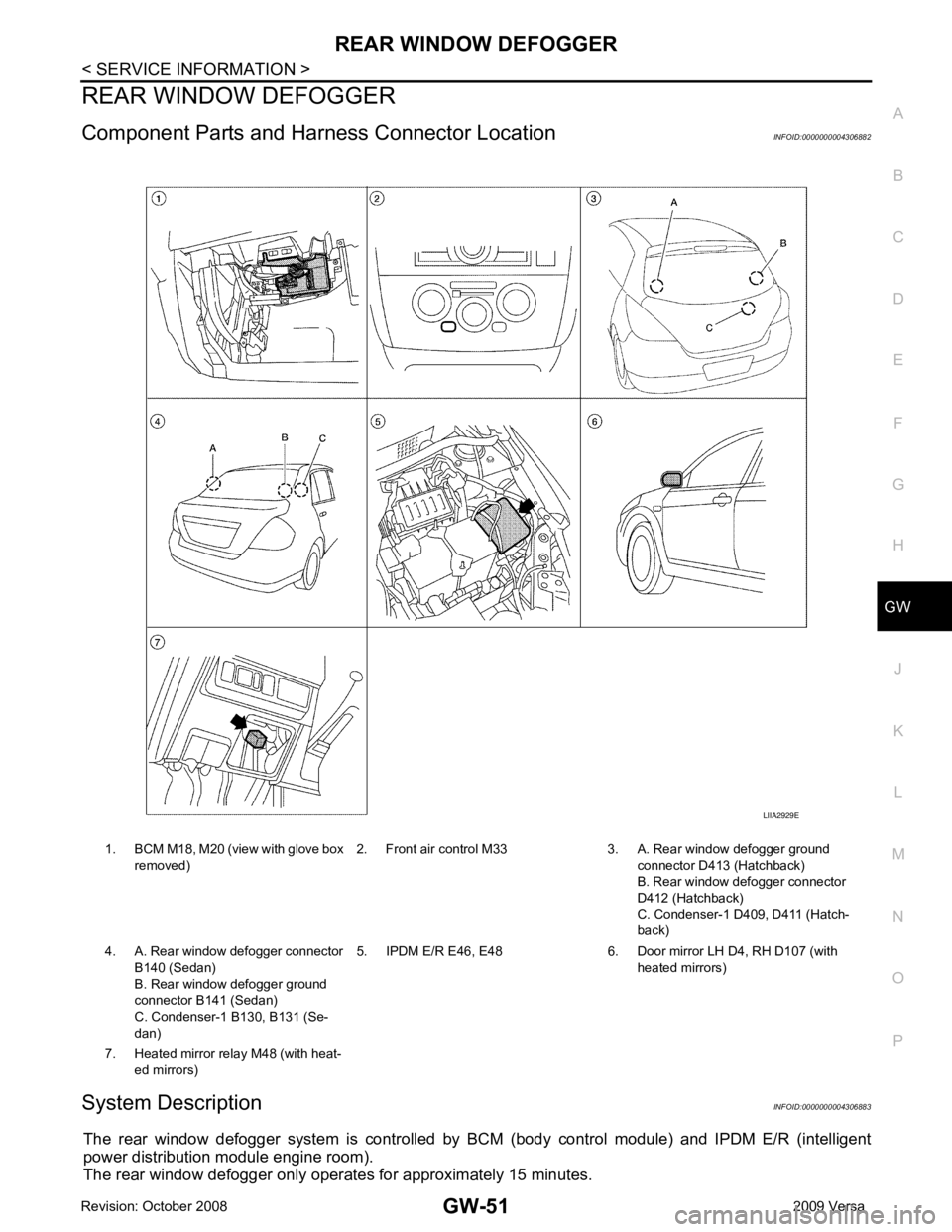
Component Parts and Har ness Connector Location INFOID:0000000004306882
System Description INFOID:0000000004306883
The rear window defogger system is controlled by BCM (body control module) and IPDM E/R (intelligent
power distribution module engine room).
The rear window defogger only operates for approximately 15 minutes. 1. BCM M18, M20 (view with glove box
removed) 2. Front air control M33 3. A. Rear window defogger ground
connector D413 (Hatchback)
B. Rear window defogger connector
D412 (Hatchback)
C. Condenser-1 D4 09, D411 (Hatch-
back)
4. A. Rear window defogger connector B140 (Sedan)
B. Rear window defogger ground
connector B141 (Sedan)
C. Condenser-1 B130, B131 (Se-
dan) 5. IPDM E/R E46, E48 6. Door mirror LH D4, RH D107 (with
heated mirrors)
7. Heated mirror relay M48 (with heat- ed mirrors)
Page 3421 of 4331
Trouble Diagnosis Procedure " for how to use CAN system specification chart.
× : Applicable
VEHICLE EQUIPMENT IDENTIFICATION INFORMATION
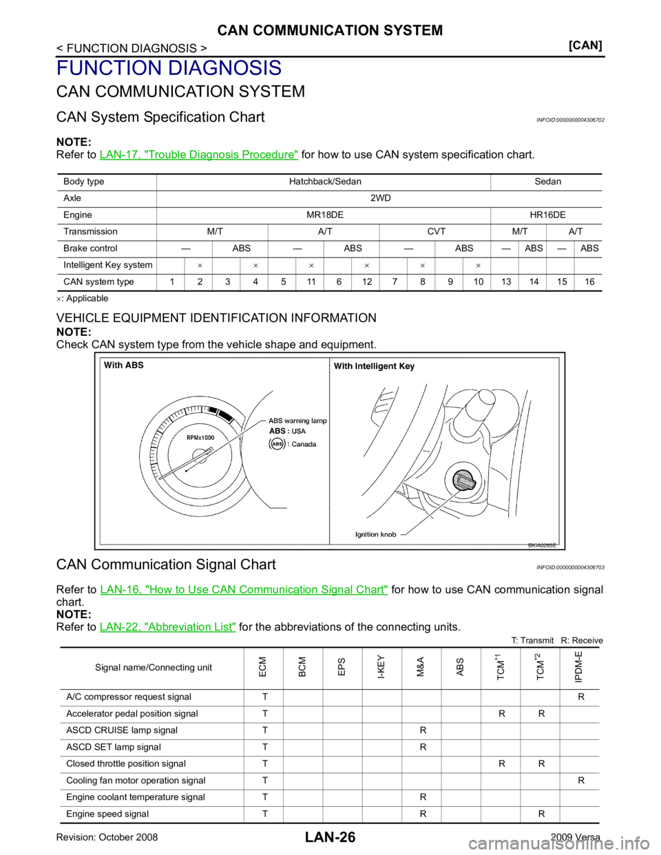
NOTE:
Check CAN system type from the vehicle shape and equipment.
CAN Communication Signal Chart INFOID:0000000004306703
Refer to LAN-16, " How to Use CAN Communication Signal Chart " for how to use CAN communication signal
chart.
NOTE:
Refer to LAN-22, " Abbreviation List " for the abbreviations of the connecting units.
T: Transmit R: Receive
Body type Hatchback/Sedan Sedan
Axle 2WD
Engine MR18DE HR16DE
Transmission M/T A/T CVT M/T A/T
Brake control — ABS — ABS — ABS — ABS — ABS
Intelligent Key system × × × × × ×
CAN system type 1 2 3 4 5 11 6 12 7 8 9 10 13 14 15 16
Page 3631 of 4331
LT
N
O P
HEADLAMP (FOR CANADA)
- DAYTIME LIGHT SYSTEM -
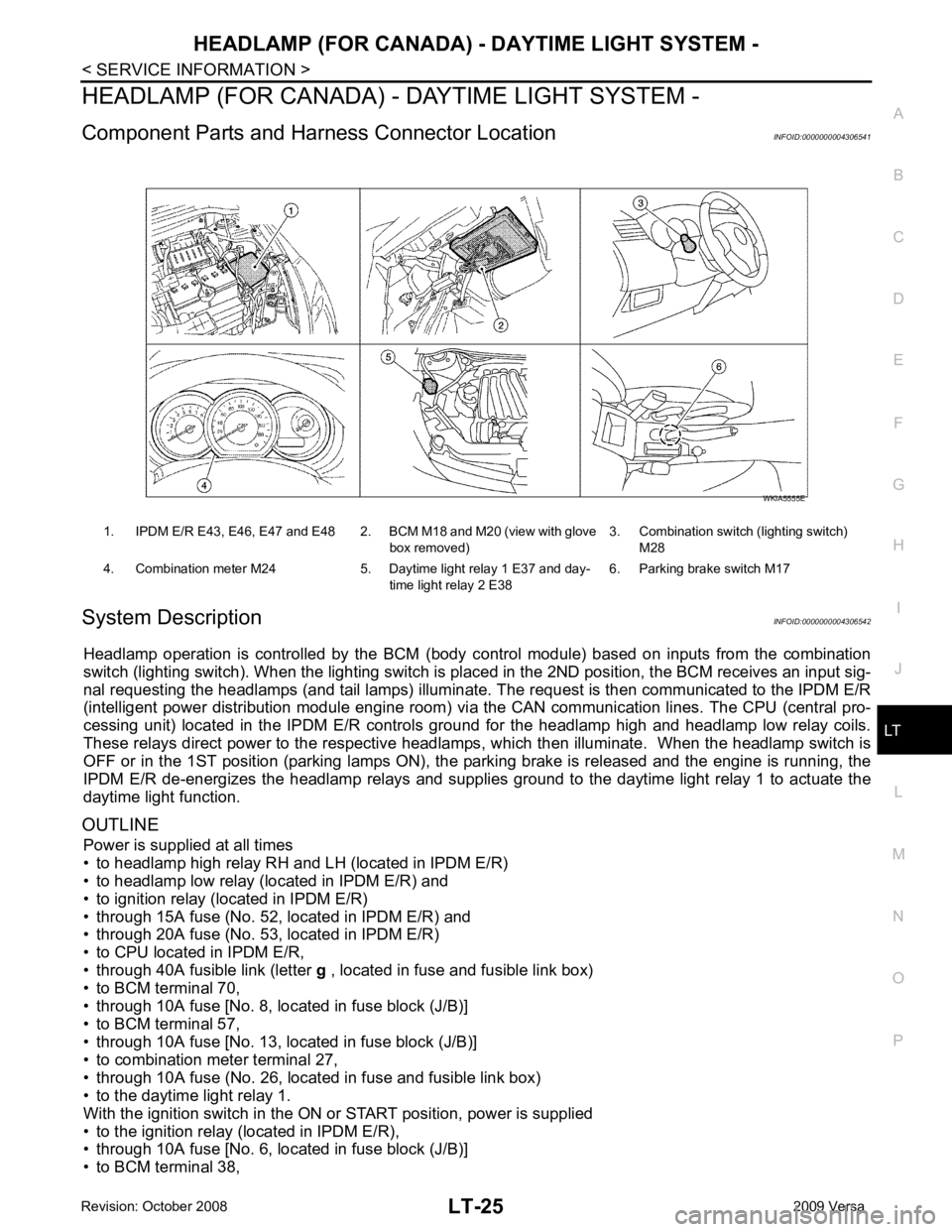
Component Parts and Har ness Connector Location INFOID:0000000004306541
System Description INFOID:0000000004306542
Headlamp operation is controlled by the BCM (body c ontrol module) based on inputs from the combination
switch (lighting switch). When the lighting switch is pl aced in the 2ND position, the BCM receives an input sig-
nal requesting the headlamps (and tail lamps) illuminate. The request is then communicated to the IPDM E/R
(intelligent power distribution module engine room) vi a the CAN communication lines. The CPU (central pro-
cessing unit) located in the IPDM E/R controls ground for the headlamp high and headlamp low relay coils.
These relays direct power to the respective headlamps , which then illuminate. When the headlamp switch is
OFF or in the 1ST position (parking lamps ON), the parking brake is released and the engine is running, the
IPDM E/R de-energizes the headlamp relays and supplies gr ound to the daytime light relay 1 to actuate the
daytime light function.
OUTLINE Power is supplied at all times
• to headlamp high relay RH and LH (located in IPDM E/R)
• to headlamp low relay (located in IPDM E/R) and
• to ignition relay (located in IPDM E/R)
• through 15A fuse (No. 52, located in IPDM E/R) and
• through 20A fuse (No. 53, located in IPDM E/R)
• to CPU located in IPDM E/R,
• through 40A fusible link (letter g , located in fuse and fusible link box)
• to BCM terminal 70,
• through 10A fuse [No. 8, located in fuse block (J/B)]
• to BCM terminal 57,
• through 10A fuse [No. 13, located in fuse block (J/B)]
• to combination meter terminal 27,
• through 10A fuse (No. 26, located in fuse and fusible link box)
• to the daytime light relay 1.
With the ignition switch in the ON or START position, power is supplied
• to the ignition relay (located in IPDM E/R),
• through 10A fuse [No. 6, located in fuse block (J/B)]
• to BCM terminal 38, 1. IPDM E/R E43, E46, E47 and E48 2. BCM M18 and M20 (view with glove
box removed)3. Combination switch (lighting switch)
M28
4. Combination meter M24 5. Daytime light relay 1 E37 and day- time light relay 2 E386. Parking brake switch M17
Page 3645 of 4331
LT
N
O P
FRONT FOG LAMP
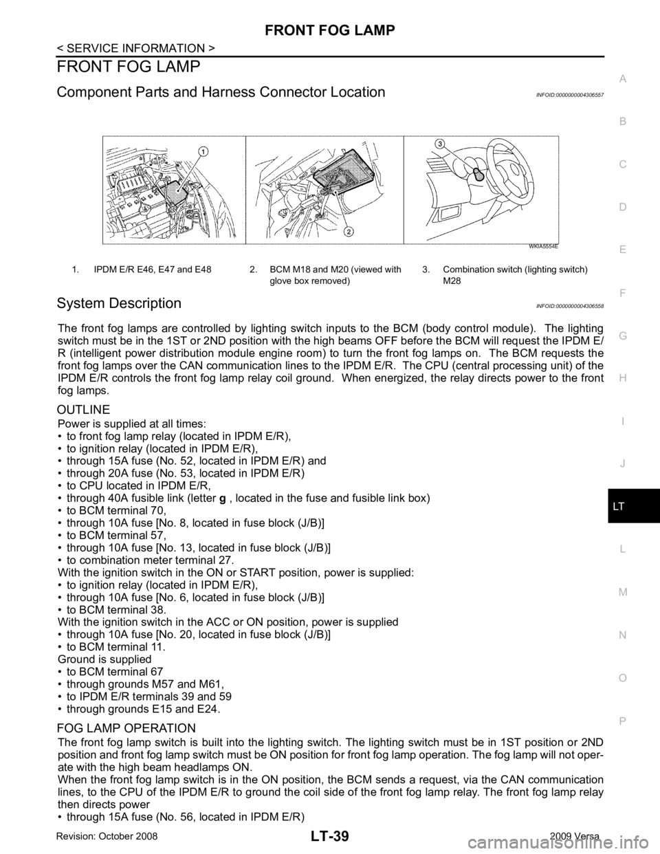
Component Parts and Har ness Connector Location INFOID:0000000004306557
System Description INFOID:0000000004306558
The front fog lamps are controlled by lighting switch inputs to the BCM (body control module). The lighting
switch must be in the 1ST or 2ND position with t he high beams OFF before the BCM will request the IPDM E/
R (intelligent power distribution module engine room) to turn the front fog lamps on. The BCM requests the
front fog lamps over the CAN communication lines to the IPDM E/R. The CPU (central processing unit) of the
IPDM E/R controls the front fog lamp relay coil ground. When energized, the relay directs power to the front
fog lamps.
OUTLINE Power is supplied at all times:
• to front fog lamp relay (located in IPDM E/R),
• to ignition relay (located in IPDM E/R),
• through 15A fuse (No. 52, located in IPDM E/R) and
• through 20A fuse (No. 53, located in IPDM E/R)
• to CPU located in IPDM E/R,
• through 40A fusible link (letter g , located in the fuse and fusible link box)
• to BCM terminal 70,
• through 10A fuse [No. 8, located in fuse block (J/B)]
• to BCM terminal 57,
• through 10A fuse [No. 13, located in fuse block (J/B)]
• to combination meter terminal 27.
With the ignition switch in the ON or START position, power is supplied:
• to ignition relay (located in IPDM E/R),
• through 10A fuse [No. 6, located in fuse block (J/B)]
• to BCM terminal 38.
With the ignition switch in the ACC or ON position, power is supplied
• through 10A fuse [No. 20, located in fuse block (J/B)]
• to BCM terminal 11.
Ground is supplied
• to BCM terminal 67
• through grounds M57 and M61,
• to IPDM E/R terminals 39 and 59
• through grounds E15 and E24.
FOG LAMP OPERATION The front fog lamp switch is built into the lighting s witch. The lighting switch must be in 1ST position or 2ND
position and front fog lamp switch must be ON position fo r front fog lamp operation. The fog lamp will not oper-
ate with the high beam headlamps ON.
When the front fog lamp switch is in the ON positi on, the BCM sends a request, via the CAN communication
lines, to the CPU of the IPDM E/R to ground the coil side of the front fog lamp relay. The front fog lamp relay
then directs power
• through 15A fuse (No. 56, located in IPDM E/R) 1. IPDM E/R E46, E47 and E48 2. BCM M18 and M20 (viewed with
glove box removed)3. Combination switch (lighting switch)
M28
Page 3679 of 4331
PARKING, LICENSE PL
ATE AND TAIL LAMPS
LT-73
< SERVICE INFORMATION >
C
D E
F
G H
I
J
L
M A
B LT
N
O P
PARKING, LICENSE PLATE AND TAIL LAMPS
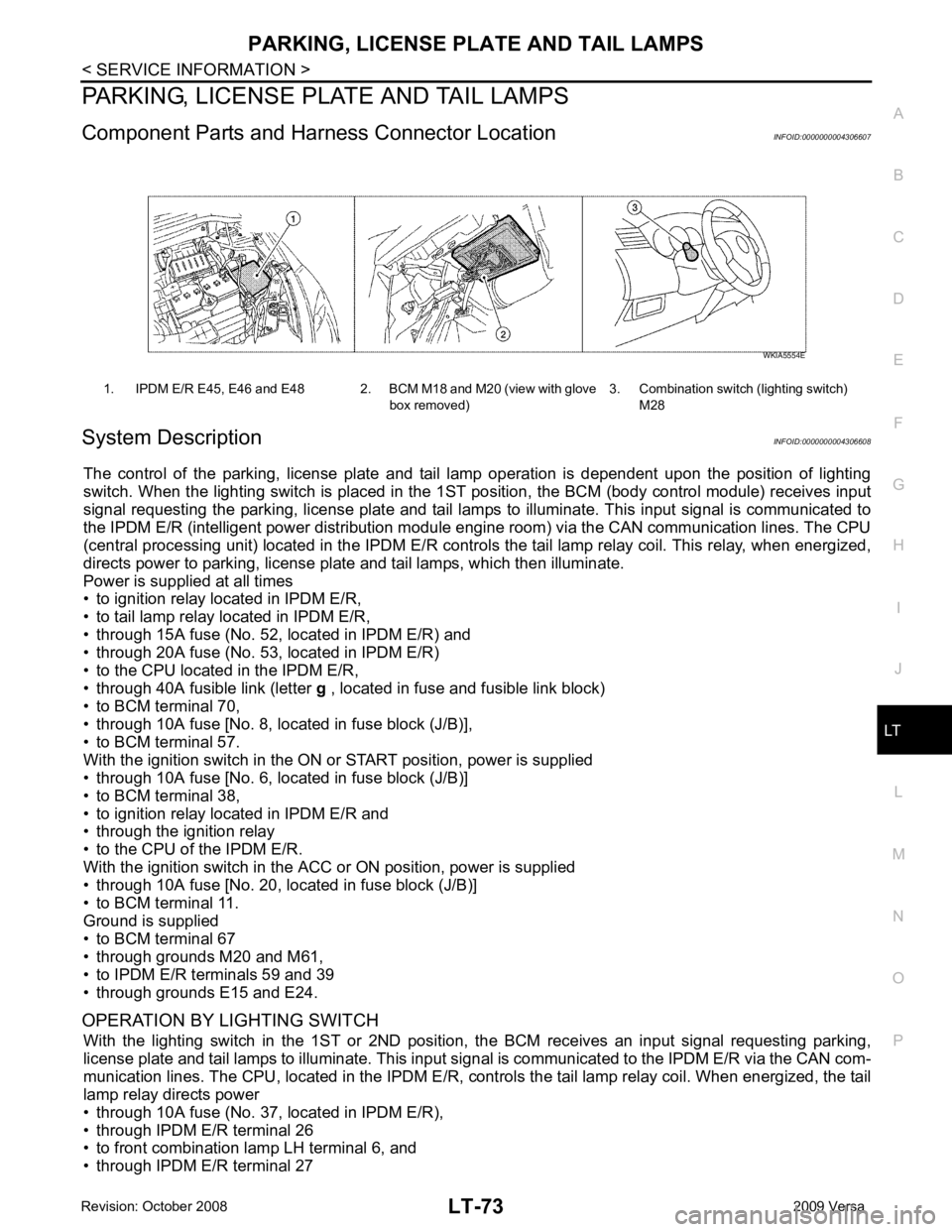
Component Parts and Har ness Connector Location INFOID:0000000004306607
System Description INFOID:0000000004306608
The control of the parking, license plate and tail lamp operation is dependent upon the position of lighting
switch. When the lighting switch is placed in the 1ST position, the BCM (body control module) receives input
signal requesting the parking, license plate and tail lamps to illuminate. This input signal is communicated to
the IPDM E/R (intelligent power distribution module engine room) via the CAN communication lines. The CPU
(central processing unit) located in the IPDM E/R contro ls the tail lamp relay coil. This relay, when energized,
directs power to parking, license plate and tail lamps, which then illuminate.
Power is supplied at all times
• to ignition relay located in IPDM E/R,
• to tail lamp relay located in IPDM E/R,
• through 15A fuse (No. 52, located in IPDM E/R) and
• through 20A fuse (No. 53, located in IPDM E/R)
• to the CPU located in the IPDM E/R,
• through 40A fusible link (letter g , located in fuse and fusible link block)
• to BCM terminal 70,
• through 10A fuse [No. 8, located in fuse block (J/B)],
• to BCM terminal 57.
With the ignition switch in the ON or START position, power is supplied
• through 10A fuse [No. 6, located in fuse block (J/B)]
• to BCM terminal 38,
• to ignition relay located in IPDM E/R and
• through the ignition relay
• to the CPU of the IPDM E/R.
With the ignition switch in the ACC or ON position, power is supplied
• through 10A fuse [No. 20, located in fuse block (J/B)]
• to BCM terminal 11.
Ground is supplied
• to BCM terminal 67
• through grounds M20 and M61,
• to IPDM E/R terminals 59 and 39
• through grounds E15 and E24.
OPERATION BY LIGHTING SWITCH With the lighting switch in the 1ST or 2ND positi on, the BCM receives an input signal requesting parking,
license plate and tail lamps to illuminate. This input si gnal is communicated to the IPDM E/R via the CAN com-
munication lines. The CPU, located in the IPDM E/R, c ontrols the tail lamp relay coil. When energized, the tail
lamp relay directs power
• through 10A fuse (No. 37, located in IPDM E/R),
• through IPDM E/R terminal 26
• to front combination lamp LH terminal 6, and
• through IPDM E/R terminal 27 1. IPDM E/R E45, E46 and E48 2. BCM M18 and M20 (view with glove
box removed)3. Combination switch (lighting switch)
M28 WKIA5554E
Page 3713 of 4331

LT
N
O P
ILLUMINATION
System Description INFOID:0000000004306640
The control of the illumination lamps operation is dependent upon the position of the lighting switch. When the
lighting switch is placed in the 1ST or 2ND position, the BCM (body control module) receives input signal
requesting the illumination lamps to illuminate. This input signal is communicated to IPDM E/R (intelligent
power distribution module engine room) across CAN communication lines. CPU (central processing unit)
located in the IPDM E/R controls the tail lamp relay coil . This relay, when energized, directs power to the illu-
mination lamps, which then illuminate.
Power is supplied at all times
• to ignition relay, located in IPDM E/R,
• to tail lamp relay, located in IPDM E/R,
• through 15A fuse (No. 52, located in IPDM E/R) and
• through 20A fuse (No. 53, located in IPDM E/R)
• to CPU located in IPDM E/R,
• through 40A fusible link (letter g, located in fuse and fusible link box)
• to BCM terminal 70, and
• through 10A fuse [No. 8, located in fuse block (J/B)]
• to BCM terminal 57.
With the ignition switch in the ON or START position, power is supplied
• to ignition relay, located in IPDM E/R, and
• through 10A fuse [No. 6, located in fuse block (J/B)]
• to BCM terminal 38.
With the ignition switch in the ACC or ON position, power is supplied
• through 10A fuse [No. 20, located in fuse block (J/B)]
• to BCM terminal 11.
Ground is supplied
• to BCM terminal 67
• through grounds M57 and M61, and
• to IPDM E/R terminals 39 and 59
• through grounds E15 and E24.
ILLUMINATION OPERATION BY LIGHTING SWITCH With the lighting switch in the 1ST or 2ND positi on, BCM receives input signal requesting the illumination
lamps to illuminate. This input signal is communicat ed to IPDM E/R across CAN communication lines. CPU
located in the IPDM E/R controls the tail lamp relay coil, which, when energized, directs power
• through 10A fuse (No. 37, located in IPDM E/R)
• through IPDM E/R terminal 29
• to microphone terminal 3 (with Bluetooth)
• to illumination control switch terminal 1
• to glove box lamp terminal 1 (with glovebox lamp)
• to audio unit terminal 9
• to front air control terminal 5
• to A/T device terminal 3 (with 4-speed A/T)
• to CVT device terminal 3 (with CVT)
• to hazard switch terminal 3
• to combination meter terminal 12
• to door mirror remote control switch terminal 16
• to combination switch (spiral cable) terminal 26 (with steering wheel audio control switches)
• to steering wheel audio control switches through combinat ion switch (spiral cable) terminal 18 (with steering
wheel audio control switches).
Ground is supplied
• to microphone terminal 2 (with Bluetooth)
• to glove box lamp terminal 2 (with glove box lamp), and
• to illumination control switch terminal 3
• through grounds M57 and M61.
The illumination control switch controls illuminat ion intensity by varying the ground to the following
• through illumination control switch terminal 2
• to audio unit terminal 8
• to front air control terminal 6