2009 NISSAN TIIDA recommended oil
[x] Cancel search: recommended oilPage 3097 of 4331
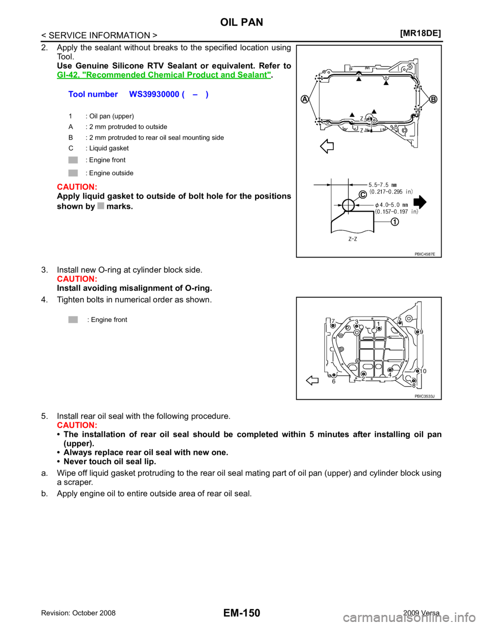
Recommended Chemical
Product and Sealant " .
CAUTION:
Apply liquid gasket to outside of bolt hole for the positions
shown by marks.
3. Install new O-ring at cylinder block side. CAUTION:
Install avoiding misalignment of O-ring.
4. Tighten bolts in numerical order as shown.
5. Install rear oil seal with the following procedure. CAUTION:
• The installation of rear oil seal should be co mpleted within 5 minutes after installing oil pan
(upper).
• Always replace rear oil seal with new one.
• Never touch oil seal lip.
a. Wipe off liquid gasket protruding to the rear oil seal mating part of oil pan (upper) and cylinder block using
a scraper.
b. Apply engine oil to entire outside area of rear oil seal. Tool number WS39930000 ( – )
1 : Oil pan (upper)
A : 2 mm protruded to outside
B : 2 mm protruded to rear oil seal mounting side
C : Liquid gasket
: Engine front
: Engine outside
Page 3099 of 4331
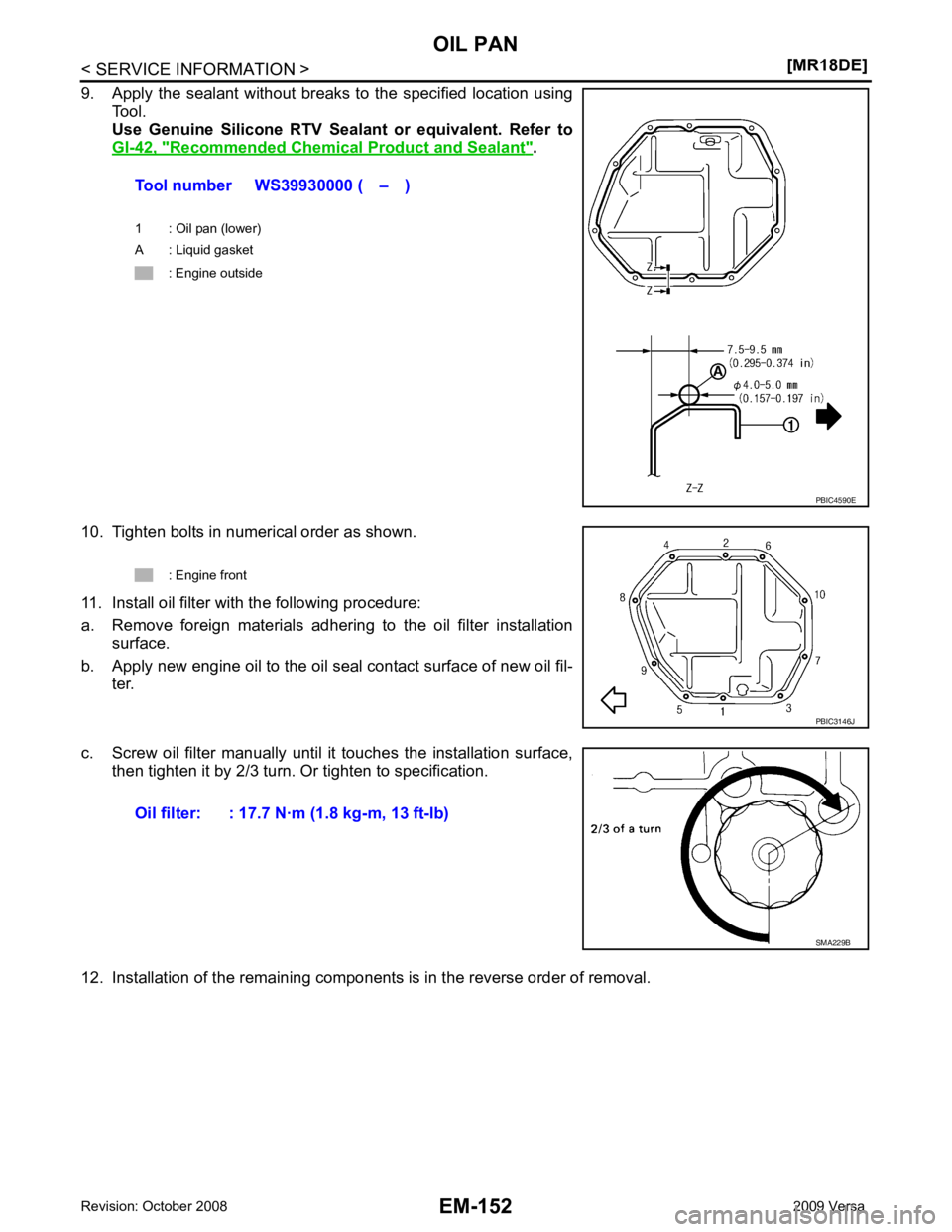
Recommended Chemical
Product and Sealant " .
10. Tighten bolts in numerical order as shown.
11. Install oil filter with the following procedure:
a. Remove foreign materials adhering to the oil filter installation surface.
b. Apply new engine oil to the oil seal contact surface of new oil fil- ter.
c. Screw oil filter manually until it touches the installation surface, then tighten it by 2/3 turn. Or tighten to specification.
12. Installation of the remaining components is in the reverse order of removal. Tool number WS39930000 ( – )
1 : Oil pan (lower)
A : Liquid gasket
: Engine outside
Page 3115 of 4331
![NISSAN TIIDA 2009 Service Repair Manual EM-168< SERVICE INFORMATION >
[MR18DE]
TIMING CHAIN
• Install front oil seal (2) using a suitable tool with outer diameter 57 mm (2.24 in) and inner diameter 45 mm (1.77 in) (A) to the
dimension sho NISSAN TIIDA 2009 Service Repair Manual EM-168< SERVICE INFORMATION >
[MR18DE]
TIMING CHAIN
• Install front oil seal (2) using a suitable tool with outer diameter 57 mm (2.24 in) and inner diameter 45 mm (1.77 in) (A) to the
dimension sho](/manual-img/5/57398/w960_57398-3114.png)
EM-168< SERVICE INFORMATION >
[MR18DE]
TIMING CHAIN
• Install front oil seal (2) using a suitable tool with outer diameter 57 mm (2.24 in) and inner diameter 45 mm (1.77 in) (A) to the
dimension shown.
CAUTION:
• Be careful not to damage front cover and crankshaft.
• Press-fit oil seal straight to avoid causing burrs or tilting.
• Never touch grease applied onto oil seal lip.
12. Install new O-ring to cylinder block. CAUTION:
Be sure O-rings are aligned properly.
13. Apply the sealant without breaks to the specified location using Tool.
Use Genuine Silicone RTV Seal ant or equivalent. Refer to
GI-42, " Recommended Chemical
Product and Sealant " .
14. Make sure that matching marks of timing chain and each sprocket are still aligned. CAUTION:
• Make sure O-ring on cylinder block is correctly installed.
• Be careful not to damage front oil seal by interference with front end of crankshaft.
1 : Front cover
: Engine front
Within 0.3 mm (0.012 in) toward engine front
Within 0.5 mm (0.020 in) toward engine rear PBIC3729E
Tool number WS39930000 ( – )
A : Liquid gasket application area
B : Liquid gasket
: Engine outside PBIC3959E
Page 3124 of 4331
![NISSAN TIIDA 2009 Service Repair Manual CAMSHAFT
EM-177
< SERVICE INFORMATION >
[MR18DE] C
D E
F
G H
I
J
K L
M A EM
NP
O
10. Install camshaft sprocket (EXH) (2).
NOTE:
Secure the hexagonal part (A) of camshaft (EXH) using wrench
to tighten NISSAN TIIDA 2009 Service Repair Manual CAMSHAFT
EM-177
< SERVICE INFORMATION >
[MR18DE] C
D E
F
G H
I
J
K L
M A EM
NP
O
10. Install camshaft sprocket (EXH) (2).
NOTE:
Secure the hexagonal part (A) of camshaft (EXH) using wrench
to tighten](/manual-img/5/57398/w960_57398-3123.png)
CAMSHAFT
EM-177
< SERVICE INFORMATION >
[MR18DE] C
D E
F
G H
I
J
K L
M A EM
NP
O
10. Install camshaft sprocket (EXH) (2).
NOTE:
Secure the hexagonal part (A) of camshaft (EXH) using wrench
to tighten bolt.
11. Install timing chain and related parts. Refer to EM-160 .
12. Inspect and adjust valve clearance. Refer to EM-178, " Valve Clearance " .
13. Installation of the remaining components is in the reverse order of removal.
INSPECTION AFTER INSTALLATION The following are procedures for chec king fluids leak, lubricates leak.
• Before starting engine, check oil/fluid levels incl uding engine coolant and engine oil. If less than required
quantity, fill to the specified level. Refer to GI-42, " Recommended Chemical Product and Sealant " .
• Use procedure below to check for fuel leakage.
- Turn ignition switch “ON” (with engine stopped). With fuel pressure applied to fuel piping, check for fuel leak-
age at connection points.
- Start engine. With engine speed increased, check again for fuel leakage at connection points.
• Run engine to check for unusual noise and vibration. NOTE:
If hydraulic pressure inside timing chain tensioner drops after removal/installation, slack in the guide may
generate a pounding noise during and just after engine start. However, this is normal. Noise will stop after
hydraulic pressure rises.
• Warm up engine thoroughly to make sure there is no leak age of fuel, or any oil/fluids including engine oil and
engine coolant.
• Bleed air from lines and hoses of applicable lines, such as in cooling system.
• After cooling down engine, again check oil/fluid levels including engine oil and engine coolant. Refill to the
specified level, if necessary.
Summary of the inspection items:
* Transmission/transaxle/CVT fluid, power steering fluid, brake fluid, etc.
Inspection of Camshaft Sprocket (INT) Oil Groove
CAUTION:
• Perform this inspection only when DTC P0011 is detected in self-diagnostic results of CONSULT-III
and it is directed according to inspect ion procedure of EC section. Refer to EC-638, " Diagnosis Pro-
cedure " (Type 1) or
EC-1153, " Diagnosis Procedure " (Type 2).
• Check when engine is cold so as to pr event burns from the splashing engine oil.
1. Check engine oil level. Refer to LU-16, " Inspection " .
2. Perform the following procedure so as to prevent the engine from being unintentionally started while checking.
a. Remove intake manifold. Refer to EM-141, " Component " .
b. Disconnect ignition coil and in jector harness connectors.
3. Remove intake valve timing control solenoid valve. Refer to EM-160, " Component " .
1 : Camshaft sprocket (INT)
Camshaft sprocket
bolt (EXH) : 88.2 N·m (9.0 kg-m, 65 ft-lb) PBIC3454J
Item Before starting engine Engine running After engine stopped
Engine coolant Level Leakage Level
Engine oil Level Leakage Level
Other oils and fluid* Level Leakage Level
Fuel Leakage Leakage Leakage
Exhaust gases — Leakage —
Page 3130 of 4331
![NISSAN TIIDA 2009 Service Repair Manual OIL SEAL
EM-183
< SERVICE INFORMATION >
[MR18DE] C
D E
F
G H
I
J
K L
M A EM
NP
O
• Drive belt; Refer to
EM-136, " Component " .
• Crankshaft pulley; Refer to EM-160, " Component " .
2. Remove fr NISSAN TIIDA 2009 Service Repair Manual OIL SEAL
EM-183
< SERVICE INFORMATION >
[MR18DE] C
D E
F
G H
I
J
K L
M A EM
NP
O
• Drive belt; Refer to
EM-136, " Component " .
• Crankshaft pulley; Refer to EM-160, " Component " .
2. Remove fr](/manual-img/5/57398/w960_57398-3129.png)
OIL SEAL
EM-183
< SERVICE INFORMATION >
[MR18DE] C
D E
F
G H
I
J
K L
M A EM
NP
O
• Drive belt; Refer to
EM-136, " Component " .
• Crankshaft pulley; Refer to EM-160, " Component " .
2. Remove front oil seal using a suitable tool. CAUTION:
Be careful not to damage front cover and crankshaft.
INSTALLATION 1. Apply new engine oil to new front oil seal joint surface and seal lip.
2. Install front oil seal so that each seal lip is oriented as shown.
• Install front oil seal (2) using a suitable tool with outer diameter57 mm (2.24 in) and inner diameter 45 mm (1.77 in) (A) to the
dimension as shown.
CAUTION:
• Be careful not to damage front cover and crankshaft.
• Press-fit oil seal straight to avoid causing burrs or tilting.
• Do not touch grease applied on oil seal lip.
3. Installation of the remaining components is in the reverse order of removal.
Removal and Installation of Rear Oil Seal INFOID:0000000004307149
REMOVAL 1. Remove transaxle assembly. Refer to MT-58 (M/T models),
AT-232 (A/T models),
CVT-182 or
CVT-354 (CVT models).
2. Remove clutch cover and clutch disk (M/T models). Refer to CL-15 .
3. Remove drive plate (A/T or CVT models) or flywheel (M/T models). Refer to EM-199, " Component " .
4. Remove rear oil seal with a suitable tool. CAUTION:
Be careful not to damage crankshaft and cylinder block.
INSTALLATION 1. Apply the liquid gasket lightly to entire outside area of new rear oil seal. Use Genuine Silicone RTV Seal ant or equivalent. Refer to GI-42, " Recommended Chemical Prod-
uct and Sealant " .
A : Dust seal lip
B : Oil seal lip
: Engine front
: Engine rear PBIC3485J
1 : Front cover
: Engine front
Within 0.3 mm (0.012 in) toward engine front
Within 0.5 mm (0.020 in) toward engine rear PBIC3729E
Page 3150 of 4331
EM
NP
O
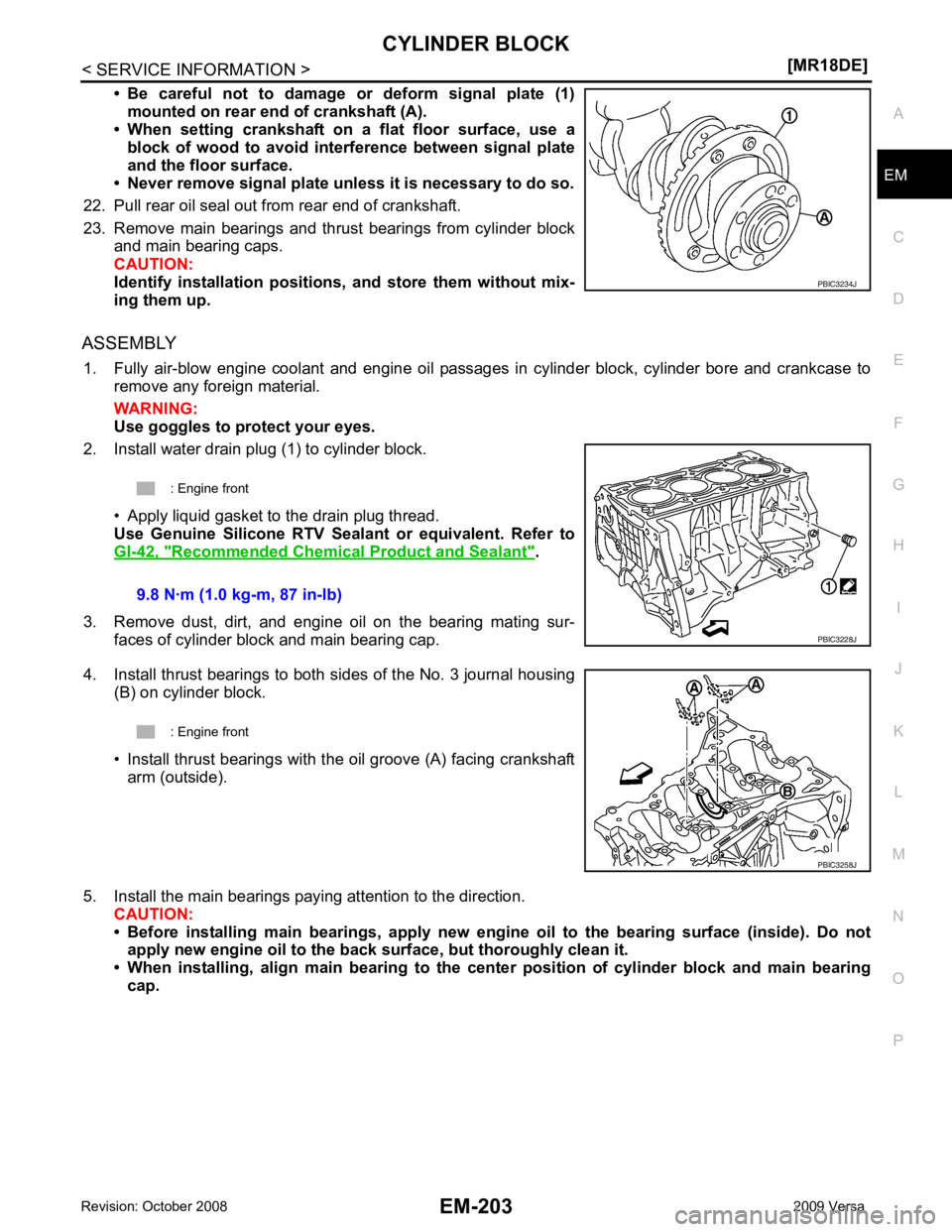
• Be careful not to damage or deform signal plate (1)
mounted on rear end of crankshaft (A).
• When setting crankshaft on a flat floor surface, use a
block of wood to avoid inte rference between signal plate
and the floor surface.
• Never remove signal plate unl ess it is necessary to do so.
22. Pull rear oil seal out from rear end of crankshaft.
23. Remove main bearings and thrust bearings from cylinder block and main bearing caps.
CAUTION:
Identify installation positions, and store them without mix-
ing them up.
ASSEMBLY 1. Fully air-blow engine coolant and engine oil passages in cylinder block, cylinder bore and crankcase to remove any foreign material.
WARNING:
Use goggles to protect your eyes.
2. Install water drain plug (1) to cylinder block.
• Apply liquid gasket to the drain plug thread.
Use Genuine Silicone RTV Seal ant or equivalent. Refer to
GI-42, " Recommended Chemical Product and Sealant " .
3. Remove dust, dirt, and engine oil on the bearing mating sur- faces of cylinder block and main bearing cap.
4. Install thrust bearings to both sides of the No. 3 journal housing (B) on cylinder block.
• Install thrust bearings with the oil groove (A) facing crankshaft arm (outside).
5. Install the main bearings paying attention to the direction. CAUTION:
• Before installing main bearings , apply new engine oil to the bearing surface (inside). Do not
apply new engine oil to the back surface, but thoroughly clean it.
• When installing, align main b earing to the center position of cylinder block and main bearing
cap.
Page 3241 of 4331
FSU
N
O P
FRONT SUSPENSION ASSEMBLY
On-Vehicle Inspection and Service INFOID:0000000004305863
Make sure the mounting conditions (looseness, back lash) of each component and component conditions
(wear, damage) are normal.
INSPECTION OF LOWER BALL JOINT END PLAY 1. Set front wheels in a straight-ahead position. Do not depress brake pedal.
2. Place an iron bar or similar tool bet ween transverse link and steering knuckle.
3. Measure axial end play by prying it up and down.
CAUTION:
Be careful not to damage ball joint boot. Do not damage the installation position by applying
excessive force.
STRUT INSPECTION Check for oil leakage, damage and replace as necessary.
Wheel Alignment Inspection INFOID:0000000004305864
PRELIMINARY INSPECTION WARNING:
Always adjust the alignment with the vehicle on a flat surface.
NOTE:
If alignment is out of specification, inspect and r eplace any damaged or worn rear suspension parts before
making any adjustments.
1. Check and adjust the wheel alignment with the vehicle under unladen conditions. “Unladen conditions”
means that the fuel, coolant, and lubricant are full; and that the spare tire, jack, hand tools and mats are in
their designated positions.
2. Check the tires for incorrect air pressure and excessive wear.
3. Check the wheels for run out and damage. Refer to WT-6, " Inspection " .
4. Check the wheel bearing axial end play. Refer to FAX-6, " On-Vehicle Inspection and Service " .
5. Check the shock absorbers for leaks or damage.
6. Check each mounting point of the suspension components for any excessive looseness or damage.
7. Check each link, arm, and the suspension member for any damage.
8. Check the vehicle height. Refer to FSU-19, " Wheelarch Height (Unladen*) " .
GENERAL INFORMATION AND RECOMMENDATIONS 1. A Four-Wheel Thrust Alignment should be performed. • This type of alignment is re commended for any NISSAN vehicle.
• The four-wheel “thrust” process helps ensure that the vehicle is properly aligned and the steering wheel
is centered.
• The alignment machine itself should be ca pable of accepting any NISSAN vehicle.
• The alignment machine should be checked to ensure that it is level.
2. Make sure the alignment machine is properly calibrated. • Your alignment machine should be regularly calib rated in order to give correct information.
• Check with the manufacturer of your specific a lignment machine for their recommended Service/Cali-
bration Schedule.
THE ALIGNMENT PROCESS IMPORTANT: Use only the alignment specifications listed in this Service Manual. Refer to FSU-17, " Wheel
Alignment (Unladen*) " .
1. When displaying the alignment settings, many alignm ent machines use “indicators”: (Green/red, plus or
minus, Go/No Go). Do NOT use these indicators.
• The alignment specifications programmed into your alignment machine that operate these indicators
may not be correct. Axial end play : 0 mm (0 in)
Page 3254 of 4331
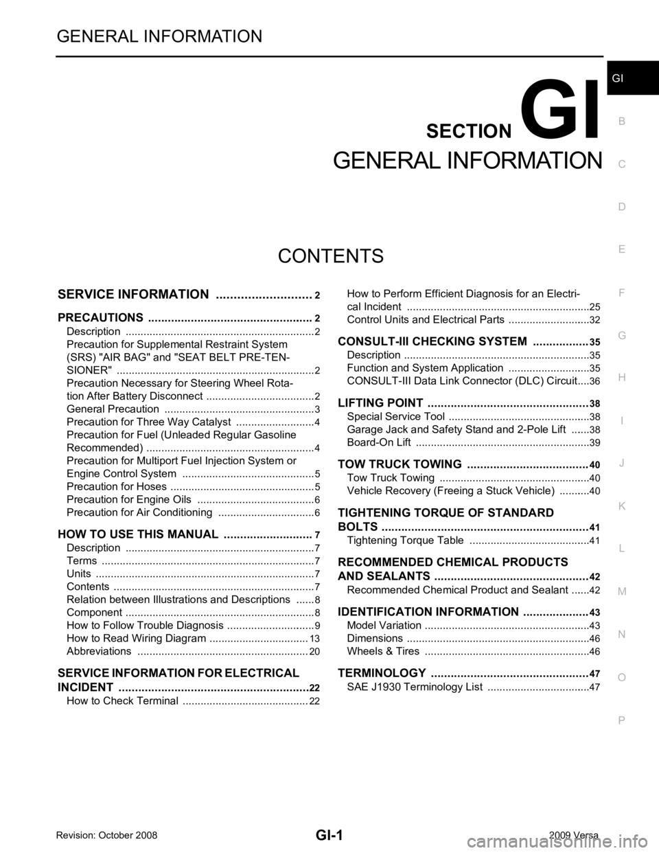
GI
SECTION GI
N
O P
CONTENTS
GENERAL INFORMATION
SERVICE INFORMATION .. ..........................2
PRECAUTIONS .............................................. .....2
Description .......................................................... ......2
Precaution for Supplemental Restraint System
(SRS) "AIR BAG" and "SEAT BELT PRE-TEN-
SIONER" ............................................................. ......
2
Precaution Necessary fo r Steering Wheel Rota-
tion After Battery Disconnect ............................... ......
2
General Precaution ............................................. ......3
Precaution for Three Way Catalyst ..................... ......4
Precaution for Fuel (Unleaded Regular Gasoline
Recommended) ................................................... ......
4
Precaution for Multiport Fuel Injection System or
Engine Control System ....................................... ......
5
Precaution for Hoses ........................................... ......5
Precaution for Engine Oils .................................. ......6
Precaution for Air Conditioning ........................... ......6
HOW TO USE THIS MANUAL ....................... .....7
Description .......................................................... ......7
Terms .................................................................. ......7
Units .................................................................... ......7
Contents .............................................................. ......7
Relation between Illustrations and Descriptions . ......8
Component .......................................................... ......8
How to Follow Trouble Diagnosis ........................ ......9
How to Read Wiring Diagr am ..................................13
Abbreviations ...................................................... ....20
SERVICE INFORMATION FOR ELECTRICAL
INCIDENT ....................................................... ....
22
How to Check Terminal ...........................................22 How to Perform Efficient Diagnosis for an Electri-
cal Incident .......................................................... ....
25
Control Units and Electrical Parts ........................ ....32
CONSULT-III CHECKING SYSTEM ................. 35
Description ........................................................... ....35
Function and System Application ........................ ....35
CONSULT-III Data Link Connector (DLC) Circuit ....36
LIFTING POINT ................................................. 38
Special Service Tool ............................................ ....38
Garage Jack and Safety Stand and 2-Pole Lift ... ....38
Board-On Lift ....................................................... ....39
TOW TRUCK TOWING ..................................... 40
Tow Truck Towing ............................................... ....40
Vehicle Recovery (Freeing a Stuck Vehicle) ....... ....40
TIGHTENING TORQUE OF STANDARD
BOLTS ............................................................... 41
Tightening Torque Table ..................................... ....41
RECOMMENDED CHEMICAL PRODUCTS
AND SEALANTS ............................................... 42
Recommended Chemical Product and Sealant ... ....42
IDENTIFICATION INFORMATION .................... 43
Model Variation .................................................... ....43
Dimensions .......................................................... ....46
Wheels & Tires .................................................... ....46
TERMINOLOGY ................................................ 47
SAE J1930 Terminology List ............................... ....47