2009 NISSAN TIIDA recommended oil
[x] Cancel search: recommended oilPage 3257 of 4331
GI-4< SERVICE INFORMATION >
PRECAUTIONS
• Replace oil seals, gaskets, packings, O-rings, locking wa shers, cotter pins, self-locking nuts, etc. with new
ones.
• Replace inner and outer races of tapered roller bearings and needle bearings as a set.
• Arrange the disassembled parts in accordance with their assembled locations and sequence.
• Do not touch the terminals of electrical com ponents which use microcomputers (such as ECM).
Static electricity may damage internal electronic components.
• After disconnecting vacuum or air hoses, atta ch a tag to indicate the proper connection.
• Use only the fluids and lubricants specified in this manual.
• Use approved bonding agent, sealants or their equivalents when required.
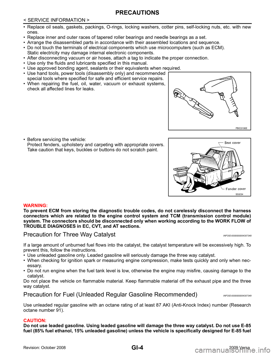
• Use hand tools, power tools (disassembly only) and recommended
special tools where specified for safe and efficient service repairs.
• When repairing the fuel, oil, water, vacuum or exhaust systems, check all affected lines for leaks.
• Before servicing the vehicle: Protect fenders, upholstery and carpeting with appropriate covers.
Take caution that keys, buckles or buttons do not scratch paint.
WARNING:
To prevent ECM from storing the diagnostic tro uble codes, do not carelessly disconnect the harness
connectors which are related to the engine cont rol system and TCM (transmission control module)
system. The connectors should be disconnected on ly when working according to the WORK FLOW of
TROUBLE DIAGNOSES in EC, CVT, and AT sections.
Precaution for Three Way Catalyst INFOID:0000000004307348
If a large amount of unburned fuel flows into the catalyst , the catalyst temperature will be excessively high. To
prevent this, follow the instructions.
• Use unleaded gasoline only. Leaded gasoline will seriously damage the three way catalyst.
• When checking for ignition spark or measuring engine compression, make tests quickly and only when nec-
essary.
• Do not run engine when the fuel tank level is low, otherwise the engine may misfire, causing damage to the
catalyst.
Do not place the vehicle on flammable material. Keep flammable material off the exhaust pipe and the three
way catalyst.
Precaution for Fuel (Unleade d Regular Gasoline Recommended) INFOID:0000000004307349
Use unleaded regular gasoline with an octane rating of at least 87 AKI (Anti-Knock Index) number (Research
octane number 91).
CAUTION:
Do not use leaded gasoline. Using leaded gasoline will damage the three way catalyst. Do not use E-85
fuel (85% fuel ethanol, 15% unl eaded gasoline) unless the vehicle is specifically designed for E-85 fuel PBIC0190E
SGI234
Page 3724 of 4331
![NISSAN TIIDA 2009 Service Repair Manual PRECAUTIONS
LU-3
< PRECAUTION >
[HR16DE] C
D E
F
G H
I
J
K L
M A LU
NP
O
Precaution for Liquid Gasket
INFOID:0000000004784386
REMOVAL OF LIQUID GASKET SEALING • After removing nuts and bolts, separa NISSAN TIIDA 2009 Service Repair Manual PRECAUTIONS
LU-3
< PRECAUTION >
[HR16DE] C
D E
F
G H
I
J
K L
M A LU
NP
O
Precaution for Liquid Gasket
INFOID:0000000004784386
REMOVAL OF LIQUID GASKET SEALING • After removing nuts and bolts, separa](/manual-img/5/57398/w960_57398-3723.png)
PRECAUTIONS
LU-3
< PRECAUTION >
[HR16DE] C
D E
F
G H
I
J
K L
M A LU
NP
O
Precaution for Liquid Gasket
INFOID:0000000004784386
REMOVAL OF LIQUID GASKET SEALING • After removing nuts and bolts, separate the mating surface, using Tool and remove old liquid gasket sealing.
CAUTION:
Be careful not to damage the mating surfaces.
• Tap Tool to insert it (1), and then slide it by tapping on the side (2) as shown.
• In areas where Tool is difficult to use, use plastic hammer to lightly tap the parts, to remove it.
CAUTION:
If for some unavoidable reason suitable tool such as screw-
driver is used, be careful not to damage the mating surfaces.
LIQUID GASKET APPLICATION PROCEDURE 1. Remove old liquid gasket adhering to the liquid gasket applica- tion surface and the mating surface, using scraper.
• Remove liquid gasket completely from the groove of the liquid
gasket application surface, bolts, and bolt holes.
2. Thoroughly clean the mating surfaces and remove adhering moisture, grease and foreign materials.
3. Attach liquid gasket tube to Tool.
Use Genuine RTV Silicone Seal ant or equivalent. Refer to GI-42, " Recommended Chemical Prod-
uct and Sealant " .
4. Apply liquid gasket without breaks to the spec ified location with the specified dimensions.
• If there is a groove for the liquid gasket application, apply liquid gasket to the groove.
• As for the bolt holes, normally apply liquid gasket inside the holes. Occasionally, it should be applied outside the holes.
Make sure to read the text of service manual.
• Within five minutes of liquid gasket application, install the mat- ing component.
• If liquid gasket protrudes, wipe it off immediately.
• Do not retighten nuts or bolts after the installation.
• After 30 minutes or more have passed from the installation, fill engine oil and engine coolant.
CAUTION:
If there are specific instructions in this manual, observe them.
Tool number : KV10111100 (J-37228)
WBIA0566E
Tool number : WS39930000 ( — )
PBIC0003E
WBIA0567E
SEM159F
Page 3729 of 4331
Engine Oil Pressure " .
If difference is extreme, check oil passage and oil pump for oil leaks.
NOTE:
When engine oil temperature is low, engine oil pressure becomes high.
6. After the inspections, install oil pressure switch as follows:
a. Remove old liquid gasket adhering to oil pressure switch and engine.
b. Apply liquid gasket and tighten oil pressure switch to specification. Use Genuine Silicone RTV Sealant or equivalent. Refer to GI-42, " Recommended Chemical Product
and Sealant " .
c. Check engine oil level.
d. After warming up engine, make sure there are no leaks of engine oil with running engine.
Draining INFOID:0000000004784338
WARNING:
• Be careful not to burn yoursel f, as engine oil may be hot.
• Prolonged and repeated contact with used engine oil may cause ski n cancer. Try to avoid direct skin
contact with used engine oil. If skin contact is made, wash thoroughly with soap or hand cleaner as
soon as possible.
1. Warm up the engine, park vehicle on a level surface and check for engine oil leakage from engine compo- nents. Refer to LU-7, " Inspection " .
2. Stop the engine and wait for 10 minutes.
3. Loosen oil filler cap.
4. Remove drain plug and then drain engine oil.
Refilling INFOID:0000000004784339
1. Install drain plug with new washer. Refer to EM-39, " Exploded View " .
CAUTION:
Be sure to clean drain plug and install with new washer.
2. Refill with new engine oil. Engine oil specification and viscosity: Refer to MA-14, " Fluids and Lubricants " .
CAUTION:
• The refill capacity depends on the engine oi l temperature and drain time. Use these specifica-
tions for reference only.
• Always use oil level gauge to determine the pr oper amount of engine oil in the engine.
3. Warm up engine and check area around drain plug and oil filter for engine oil leakage.
4. Stop engine and wait for 10 minutes.
5. Check the engine oil level. Refer to LU-7, " Inspection " .
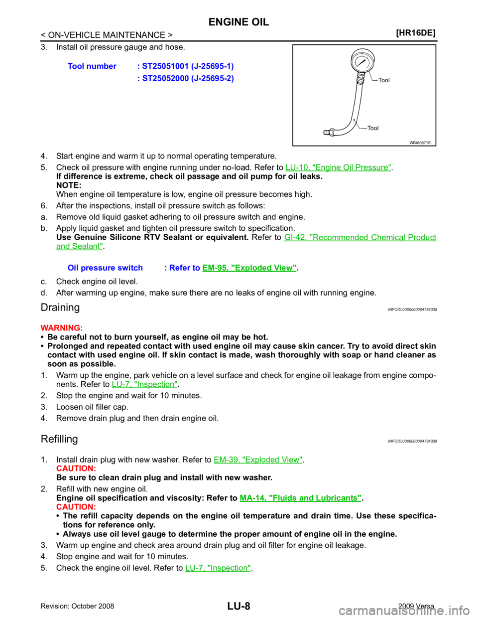
Tool number : ST25051001 (J-25695-1)
: ST25052000 (J-25695-2) Exploded View " .
Page 3733 of 4331
![NISSAN TIIDA 2009 Service Repair Manual LU-12< SERVICE INFORMATION >
[MR18DE]
PRECAUTIONS
Precaution for Liquid Gasket INFOID:0000000004788557
REMOVAL OF LIQUID GASKET SEALING
• After removing nuts and bolts, separate the mating surface, NISSAN TIIDA 2009 Service Repair Manual LU-12< SERVICE INFORMATION >
[MR18DE]
PRECAUTIONS
Precaution for Liquid Gasket INFOID:0000000004788557
REMOVAL OF LIQUID GASKET SEALING
• After removing nuts and bolts, separate the mating surface,](/manual-img/5/57398/w960_57398-3732.png)
LU-12< SERVICE INFORMATION >
[MR18DE]
PRECAUTIONS
Precaution for Liquid Gasket INFOID:0000000004788557
REMOVAL OF LIQUID GASKET SEALING
• After removing nuts and bolts, separate the mating surface, using Tool and remove old liquid gasket sealing.
CAUTION:
Be careful not to damage the mating surfaces.
• Tap Tool to insert it (1), and then slide it by tapping on the side (2) as shown.
• In areas where Tool is difficult to use, use plastic hammer to lightly tap the parts, to remove it.
CAUTION:
If for some unavoidable reason suitable tool such as screw-
driver is used, be careful no t to damage the mating surfaces.
LIQUID GASKET APPLICATION PROCEDURE
1. Remove old liquid gasket adhering to the liquid gasket applica- tion surface and the mating surface, using scraper.
• Remove liquid gasket completely from the groove of the liquid
gasket application surface, bolts, and bolt holes.
2. Thoroughly clean the mating surfaces and remove adhering moisture, grease and foreign materials.
3. Attach liquid gasket tube to Tool.
Use Genuine RTV Silicone Seal ant or equivalent. Refer to GI-42, " Recommended Chemical Prod-
uct and Sealant " .
4. Apply liquid gasket without breaks to the specif ied location with the specified dimensions.
• If there is a groove for the liquid gasket application, apply liquid gasket to the groove.
• As for the bolt holes, normally apply liquid gasket inside the holes. Occasionally, it should be applied outside the holes.
Make sure to read the text of service manual.
• Within five minutes of liquid gasket application, install the mat- ing component.
• If liquid gasket protrudes, wipe it off immediately.
• Do not retighten nuts or bolts after the installation.
• After 30 minutes or more have passed from the installation, fill engine oil and engine coolant.
CAUTION:
If there are specific instructions in this manual, observe them.
Tool number : KV10111100 (J-37228)
WBIA0566E
Tool number : WS39930000 ( — )
PBIC0003E
WBIA0567E
SEM159F
Page 3738 of 4331
![NISSAN TIIDA 2009 Service Repair Manual ENGINE OIL
LU-17
< SERVICE INFORMATION >
[MR18DE] C
D E
F
G H
I
J
K L
M A LU
NP
O
4. Install oil pressure gauge and hose.
5. Start engine and warm it up to normal operating temperature.
6. Check oil p NISSAN TIIDA 2009 Service Repair Manual ENGINE OIL
LU-17
< SERVICE INFORMATION >
[MR18DE] C
D E
F
G H
I
J
K L
M A LU
NP
O
4. Install oil pressure gauge and hose.
5. Start engine and warm it up to normal operating temperature.
6. Check oil p](/manual-img/5/57398/w960_57398-3737.png)
ENGINE OIL
LU-17
< SERVICE INFORMATION >
[MR18DE] C
D E
F
G H
I
J
K L
M A LU
NP
O
4. Install oil pressure gauge and hose.
5. Start engine and warm it up to normal operating temperature.
6. Check oil pressure with engine running under no-load. Refer to LU-22, " Standard and Limit " .
If difference is extreme, check oi l passage and oil pump for oil leaks.
NOTE:
When engine oil temperature is low, engine oil pressure becomes high.
7. After the inspections, install oil pressure switch as follows:
a. Remove old liquid gasket adhering to oil pressure switch and engine.
b. Apply liquid gasket and tighten oil pressure switch to specification. Use Genuine Silicone RT V Sealant or equivalent. Refer to GI-42, " Recommended Chemical Product
and Sealant " .
c. Check engine oil level.
d. After warming up engine, make sure there are no leaks of engine oil with running engine.
Changing Engine Oil INFOID:0000000004307169
WARNING:
• Be careful not to burn yoursel f, as engine oil may be hot.
• Prolonged and repeated contact with used engine oil may cause skin cancer. Try to avoid direct skin
contact with used engine oil. If skin contact is made, wash thorough ly with soap or hand cleaner as
soon as possible.
1. Warm up the engine, park vehicle on a level surf ace and check for engine oil leakage from engine compo-
nents. Refer to LU-16, " Inspection " .
2. Stop the engine and wait for 10 minutes. Tool number : ST25051001 (J-25695-1)
: ST25052000 (J-25695-2) WBIA0571E
Oil pressure switch : 14.7 N·
m (1.5 kg-m, 11 ft-lb)
Page 3744 of 4331
MA
N
O P
CONTENTS
MAINTENANCE
SERVICE INFORMATION .. ..........................3
PRECAUTIONS .............................................. .....3
Precaution for Supplemental Restraint System
(SRS) "AIR BAG" and "SEAT BELT PRE-TEN-
SIONER" ............................................................. ......
3
Precaution Necessary fo r Steering Wheel Rota-
tion After Battery Disconnect ............................... ......
3
PREPARATION .............................................. .....5
Special Service Tool ........................................... ......5
Commercial Service Tool .................................... ......5
GENERAL MAINTE NANCE ........................... .....6
Explanation of General Maintenance .................. ......6
General Maintenance .......................................... ......6
PERIODIC MAINTENANCE ........................... .....9
Introduction of Periodic Maintenance .................. ......9
Schedule 1 .......................................................... ......9
Schedule 2 .......................................................... ....11
RECOMMENDED FLUIDS AND LUBRI-
CANTS ............................................................ ....
14
Fluids and Lubricants .......................................... ....14
SAE Viscosity Number ........................................ ....14
Anti-freeze Coolant Mixture Ratio ....................... ....15
ENGINE MAINTENANCE (HR16DE) ............. ....16
DRIVE BELT .......................................................... ....16
DRIVE BELT : Checking ..................................... ....16
DRIVE BELT : Tension Adjustment .................... ....16
ENGINE COOLANT ............................................... ....17
ENGINE COOLANT : Inspection ......................... ....17
ENGINE COOLANT : Changing Engine Coolant .... 17
FUEL LINES .......................................................... ....19
FUEL LINES : Checking Fuel Line ...................... ....19
AIR CLEANER FILTER ......................................... ....19 AIR CLEANER FILTER : Re
moval and Installation
....20
ENGINE OIL ........................................................... ....20
ENGINE OIL : Inspection ..................................... ....20
ENGINE OIL : Draining ........................................ ....22
ENGINE OIL : Refilling ........................................ ....22
OIL FILTER ............................................................ ....22
OIL FILTER : Removal and Installation ...................23
SPARK PLUG (HR16DE) ...................................... ....23
SPARK PLUG (HR16DE) : Exploded View ......... ....24
SPARK PLUG (HR16DE) : Removal and Installa-
tion ....................................................................... ....
24
EVAP VAPOR LINES ............................................ ....25
EVAP VAPOR LINES : Checking EVAP Vapor
Line ...................................................................... ....
25
ENGINE MAINTENANCE (MR18DE) ............... 26
DRIVE BELT .......................................................... ....26
DRIVE BELT : Component .................................. ....26
DRIVE BELT : Checking Drive Belts ................... ....26
DRIVE BELT : Tension Adjustment ..................... ....26
ENGINE COOLANT ............................................... ....26
ENGINE COOLANT : Inspection ......................... ....26
ENGINE COOLANT : Changing Engine Coolant .... 27
FUEL LINES ........................................................... ....29
FUEL LINES : Checking Fuel Line ...................... ....29
AIR CLEANER FILTER ......................................... ....29
AIR CLEANER FILTER : Component .................. ....29
AIR CLEANER FILTER : Changing Air Cleaner
Filter ..................................................................... ....
30
ENGINE OIL ........................................................... ....30
ENGINE OIL : Inspection ..................................... ....30
ENGINE OIL : Changing Engine Oil .................... ....32
OIL FILTER ............................................................ ....33
Page 3763 of 4331
MA-20< SERVICE INFORMATION >
ENGINE MAINTENANCE (HR16DE)
AIR CLEANER FILTER : Removal and Installation INFOID:0000000004806007
REMOVAL
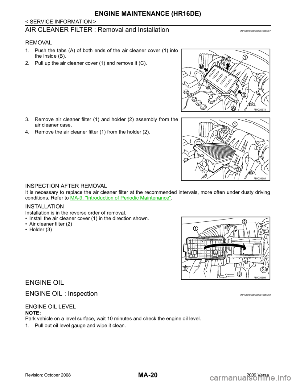
1. Push the tabs (A) of both ends of the air cleaner cover (1) into the inside (B).
2. Pull up the air cleaner cover (1) and remove it (C).
3. Remove air cleaner filter (1) and holder (2) assembly from the air cleaner case.
4. Remove the air cleaner filter (1) from the holder (2).
INSPECTION AFTER REMOVAL
It is necessary to replace the air cleaner filter at the recommended intervals, more often under dusty driving
conditions. Refer to MA-9, " Introduction of Periodic Maintenance " .
INSTALLATION
Installation is in the reverse order of removal.
• Install the air cleaner cover (1) in the direction shown.
• Air cleaner filter (2)
• Holder (3)
ENGINE OIL
ENGINE OIL : Inspection INFOID:0000000004806010
ENGINE OIL LEVEL
NOTE:
Park vehicle on a level surface, wait 10 minutes and check the engine oil level.
1. Pull out oil level gauge and wipe it clean. PBIC3557J
PBIC3558J
PBIC3559J
Page 3765 of 4331
MA-22< SERVICE INFORMATION >
ENGINE MAINTENANCE (HR16DE)
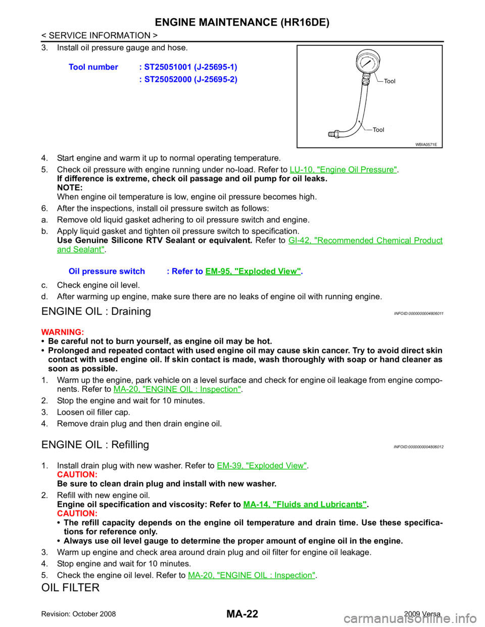
3. Install oil pressure gauge and hose.
4. Start engine and warm it up to normal operating temperature.
5. Check oil pressure with engine running under no-load. Refer to LU-10, " Engine Oil Pressure " .
If difference is extreme, check oil passage and oil pump for oil leaks.
NOTE:
When engine oil temperature is low, engine oil pressure becomes high.
6. After the inspections, install oil pressure switch as follows:
a. Remove old liquid gasket adhering to oil pressure switch and engine.
b. Apply liquid gasket and tighten oil pressure switch to specification. Use Genuine Silicone RTV Sealant or equivalent. Refer to GI-42, " Recommended Chemical Product
and Sealant " .
c. Check engine oil level.
d. After warming up engine, make sure there are no leaks of engine oil with running engine.
ENGINE OIL : Draining INFOID:0000000004806011
WARNING:
• Be careful not to burn yoursel f, as engine oil may be hot.
• Prolonged and repeated contact with used engine oil may cause ski n cancer. Try to avoid direct skin
contact with used engine oil. If skin contact is made, wash thoroughly with soap or hand cleaner as
soon as possible.
1. Warm up the engine, park vehicle on a level surface and check for engine oil leakage from engine compo- nents. Refer to MA-20, " ENGINE OIL : Inspection " .
2. Stop the engine and wait for 10 minutes.
3. Loosen oil filler cap.
4. Remove drain plug and then drain engine oil.
ENGINE OIL : Refilling INFOID:0000000004806012
1. Install drain plug with new washer. Refer to EM-39, " Exploded View " .
CAUTION:
Be sure to clean drain plug and install with new washer.
2. Refill with new engine oil. Engine oil specification and viscosity: Refer to MA-14, " Fluids and Lubricants " .
CAUTION:
• The refill capacity depends on the engine oi l temperature and drain time. Use these specifica-
tions for reference only.
• Always use oil level gauge to determine the pr oper amount of engine oil in the engine.
3. Warm up engine and check area around drain plug and oil filter for engine oil leakage.
4. Stop engine and wait for 10 minutes.
5. Check the engine oil level. Refer to MA-20, " ENGINE OIL : Inspection " .
OIL FILTER Tool number : ST25051001 (J-25695-1)
: ST25052000 (J-25695-2) WBIA0571E
Oil pressure switch : Refer to
EM-95, " Exploded View " .