Page 354 of 4331

ASSEMBLY
AT-349
< SERVICE INFORMATION >
D
E
F
G H
I
J
K L
M A
B AT
N
O P
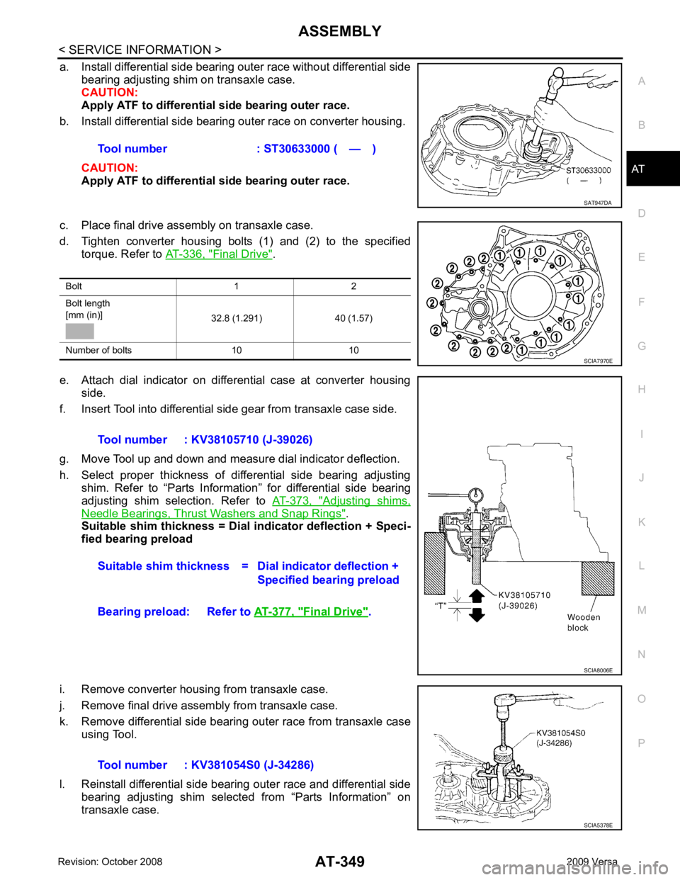
a. Install differential side bearing outer race without differential side
bearing adjusting shim on transaxle case.
CAUTION:
Apply ATF to differential side bearing outer race.
b. Install differential side bearing outer race on converter housing.
CAUTION:
Apply ATF to differential side bearing outer race.
c. Place final drive assembly on transaxle case.
d. Tighten converter housing bolts (1) and (2) to the specified torque. Refer to AT-336, " Final Drive " .
e. Attach dial indicator on differential case at converter housing side.
f. Insert Tool into differential side gear from transaxle case side.
g. Move Tool up and down and measure dial indicator deflection.
h. Select proper thickness of differential side bearing adjusting shim. Refer to “Parts Information” for differential side bearing
adjusting shim selection. Refer to AT-373, " Adjusting shims,
Needle Bearings, Thrust Washers and Snap Rings " .
Suitable shim thickness = Dial indicator deflection + Speci-
fied bearing preload
i. Remove converter housing from transaxle case.
j. Remove final drive assembly from transaxle case.
k. Remove differential side bearing outer race from transaxle case using Tool.
l. Reinstall differential side bearing outer race and differential side bearing adjusting shim selected from “Parts Information” on
transaxle case. Tool number : ST30633000 ( — ) SAT947DA
Bolt 1 2
Bolt length
[mm (in)] 32.8 (1.291) 40 (1.57)
Number of bolts 10 10 SCIA7970E
Tool number : KV38105710 (J-39026)
Suitable shim thickness = D ial indicator deflection +
Specified bearing preload
Bearing preload: Refer to AT-377, " Final Drive " .
SCIA8006E
Tool number : KV381054S0 (J-34286)
SCIA5378E
Page 369 of 4331
" Component " .
14. Apply compressed air into oil holes of transaxle case and check operation of brake band.
15. Select proper thickness of differential side bear ing adjusting shim using the following procedures.
(HR16DE engine models)
• Measure differential side bearing end play, and calculat e the adjusting shim thickness so that the end
play is within the specifications. Anchor end pin bolt : 4.9
N·m (0.50 kg-m, 43 in-lb) SAT395D
SAT396D
Total End
Play "
Page 370 of 4331
AT
N
O P
a. Place a straightedge (A) onto tr
ansaxle case (1), and measure
the depth (T) of transaxle case (1) to the mating surface for dif-
ferential side bearing using depth gauge (B).
T = (measurement) - (Straightedge thickness
• Measure the T in at least two places, and take the average.
b. Install final drive assembly onto converter housing(1).
c. Place straightedge (A) onto differential case (2), and measure the height (U) to the end of the converter housing (1) using
depth gauge (B).
16. Install differential side bearing adjusting shim selected in differ- ential side bearing end play adjustment step to transaxle case.
(HR16DE engine models only)
17. Install final drive assembly on transaxle case.
18. Install differential lubricant tube (1) and clips (2) on converter housing.
: Bolt
19. Tighten differential lubricant tube bolts to the specified torque. Refer to AT-236, " Component " .
SCIA7817E
Page 371 of 4331
AT-366< SERVICE INFORMATION >
ASSEMBLY
20. Install O-ring on differential oil port of transaxle case.
21. Apply recommended (Genuine Anaerobic Liquid Gasket or equivalent) to transaxle case as shown.
: Inside of transaxle case
CAUTION:
Completely remove all moisture, oil and old sealant, etc.
from the transaxle case and converter housing mating sur-
faces.
22. Install converter housing on transaxle case.
23. Install bracket on converter housing.
24. Tighten converter housing bolts (1) and (2) to the specified torque. Refer to AT-236, " Component " .
• HR16DE engine models
• MR18DE engine models
25. Install plug or speedometer pinion according to the following procedures. SCIA3281E
(A) : 3 - 5 mm (0.12 - 0.20 in)
(B) : 8 mm (0.31 in) R
(C) : 1.5 mm (0.059 in) dia.
(D) : 4 mm (0.16 in) SCIA7089E
Bolt 1 2
Bolt length
[mm (in)] 30 (1.18) 40 (1.57)
Number of bolts 10 10 SCIA6211J
Bolt 1 2
Bolt length
[mm (in)] 32.8 (1.291) 40 (1.57)
Number of bolts 10 10 SCIA7970E
Page 382 of 4331

AT
N
O P
Final Drive
INFOID:0000000004807941
DIFFERENTIAL SIDE GEAR CLEARANCE
DIFFERENTIAL SIDE BEARING END PL AY (FOR HR16DE ENGINE MODELS)
BEARING PRELOAD (FOR MR18DE ENGINE MODELS)
TURNING TORQUE (FOR MR18DE ENGINE MODELS)
Planetary Carrier INFOID:0000000004305543
Oil Pump INFOID:0000000004305544
Input Shaft INFOID:0000000004305545
SEAL RING CLEARANCE
SEAL RING Unit: mm (in)
Reduction Pinion Gear INFOID:0000000004305546
TURNING TORQUE
Band Servo INFOID:0000000004305547
RETURN SPRINGS Clearance between side gear and differential case with washer [mm (in)] 0.1 - 0.2 (0.004 - 0.008) Differential side bearing end play mm (in) 0 - 0.15 (0 - 0.0059)
Differential side bearing preload mm (in) 0.05 - 0.09 (0.0020 - 0.0035)
Turning torque of final drive assembly N-m (kg-cm, in-lb) 0.68 - 1.26 (7.0 - 13.0, 6.0 - 11.0)
Clearance between planetary carrier and pinion washer [mm (in)]
Standard 0.15 - 0.70 (0.0059 - 0.0276)
Allowable limit 0.80 (0.0315) Oil pump side clearance
0.02 - 0.04 (0.0008 - 0.0016)
Clearance between oil pump housing and outer gear [mm (in)] Standard 0.08 - 0.15 (0.0031 - 0.0059)
Allowable limit 0.15 (0.0059)
Oil pump cover seal ring clearance [mm (in)] Standard 0.10 - 0.25 (0.0039 - 0.0098)
Allowable limit 0.25 (0.0098) Input shaft seal ring clearance [mm (in)]
Standard 0.08 - 0.23 (0.0031 - 0.0091)
Allowable limit 0.23 (0.091) Outer diameter Inner diameter Width
24 (0.94) 20.4 (0.803) 1.97 (0.0776) Turning torque of reduction pinion gear [N·m (kg-m, in-lb)] 0.11 - 0.69 (0.01 - 0.07, 1 - 6)
Page 805 of 4331

BR
N
O P
NOISE, VIBRATION AND HARSHN
ESS (NVH) TROUBLESHOOTING
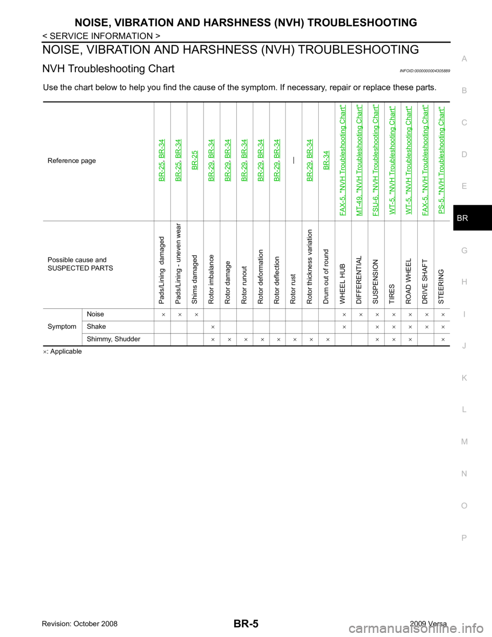
NVH Troubleshooting Chart INFOID:0000000004305889
Use the chart below to help you find t he cause of the symptom. If necessary, repair or replace these parts.
× : ApplicableReference pageBR-25
,
BR-34
BR-25
, BR-34BR-25
BR-29
, BR-34
BR-29
, BR-34
BR-29
, BR-34
BR-29
, BR-34
BR-29
, BR-34—
BR-29, BR-34BR-34
FAX-5, "
NVH Troubleshooting Chart
"
MT-49, "
NVH Troubleshooting Chart
"
FSU-6, "
NVH Troubleshooting Chart
"
WT-5, "
NVH Troubleshooting Chart
"
WT-5, "
NVH Troubleshooting Chart
"
FAX-5, "
NVH Troubleshooting Chart
"
PS-5, "
NVH Troubleshooting Chart
" Possible cause and
SUSPECTED PARTS
Pads/Lining damaged
Pads/Lining - uneven wear
Shims damaged
Rotor imbalance
Rotor damage
Rotor runout
Rotor deformation
Rotor deflection
Rotor rust
Rotor thickness variation
Drum out of round
WHEEL HUB
DIFFERENTIAL
SUSPENSION
TIRES
ROAD WHEEL
DRIVE SHAFT
STEERING
Symptom Noise
× × × × × × × × × ×
Shake × × × × × × ×
Shimmy, Shudder × × × × × × × × × × × ×
Page 1125 of 4331
CVT
N
O P
DIFFERENTIAL SIDE OIL SEAL
Removal and Installation INFOID:0000000004667115
COMPONENTS
REMOVAL 1. Remove drive shaft assembly. Refer to FAX-9 .
2. Remove differential side oil seal using a suitable tool. CAUTION:
Do not scratch transaxle case or converter housing.
INSTALLATION 1. Drive the new differential side oil seal into the transaxle case side (B) and converter housing side (C) until it is flush using
Tool.
Unit: mm (in)
CAUTION:
• Do not reuse differential side oil seals.
• Apply specified NISSAN CVT fluid to side oil seals.
2. Install drive shaft assembly. Refer to FAX-9 .
3. Check CVT fluid level and leakage. Refer to CVT-17, " Checking CVT Fluid " .
1. CVT 2. Differential side oil seal : Apply CVT Fluid NS-2.
Page 1139 of 4331
PREPARATION
CVT-195
< SERVICE INFORMATION >
[RE0F08B] D
E
F
G H
I
J
K L
M A
B CVT
N
O P
PREPARATION
Special Service Tool INFOID:0000000004305568
The actual shapes of Kent-Moore tools may differ fr om those of special service tools illustrated here.
Commercial Service Tool INFOID:0000000004305569
Tool number
(Kent-Moore No.)
Tool name Description
—
(OTC3492)
Oil pressure gauge set Measuring line pressure
—
(J-47244)
Drift Installing differential side oil seal
• Transaxle case side (left)
a: 65.83 mm (2.59 in) dia.
b: 53.85 mm (2.12 in) dia.
ST33400001
(J-47005)
Drift Installing differential side oil seal
• Converter housing side (right)
a: 69.85 mm (2.75 in) dia.
b: 49.53 mm (1.95 in) dia. SCIA7531E
SCIA5777E
SCIA5777E
Tool number
Tool name Description
Power tool Loosening nuts and bolts PBIC0190E