Page 1145 of 4331
CVT SYSTEM
CVT-201
< SERVICE INFORMATION >
[RE0F08B] D
E
F
G H
I
J
K L
M A
B CVT
N
O P
CVT SYSTEM
Cross-Sectional View - RE0F08B INFOID:0000000004305573
1. Converter housing 2. Oil pump 3. Forward clutch
4. Reverse brake 5. Planetary carrier 6. Primary pulley
7. Steel belt 8. Sun gear 9. Side cover
10. Internal gear 11. Secondary pulley 12. Differential case
13. Final gear 14. Idler gear 15. Reduction gear
16. Output gear 17. Parking gear 18. Input shaft
19. Torque converter SCIA8015E
Page 1297 of 4331
DIFFERENTIAL SIDE OIL SEAL
CVT-353
< SERVICE INFORMATION >
[RE0F08B] D
E
F
G H
I
J
K L
M A
B CVT
N
O P
DIFFERENTIAL SIDE OIL SEAL
Removal and Installation INFOID:0000000004305823
COMPONENTS
REMOVAL 1. Remove drive shaft assembly. Refer to FAX-9 .
2. Remove differential side oil seal using a suitable tool. CAUTION:
Do not scratch transaxle case or converter housing.
INSTALLATION 1. Drive the new differential side oil seal into the transaxle case side (B) and converter housing side (C) until it is flush using
Tool.
Unit: mm (in)
CAUTION:
• Do not reuse differential side oil seals.
• Apply specified NISSAN CVT fluid to side oil seals.
2. Install drive shaft assembly. Refer to FAX-9 .
3. Check CVT fluid level and leakage. Refer to CVT-196, " Checking CVT Fluid " .
1. CVT 2. Differential side oil seal : Apply CVT Fluid NS-2. WCIA0610E
SCIA2412E
Tool number : — (J-47244)
: ST33400001 (J-47005)
Dimensions (A) 0 ±0.5 (0 ±0.020) WCIA0611E
Page 3174 of 4331

EM
NP
O
SERVICE DATA AND SPECIFICATIONS (SDS)
Standard and Limit INFOID:0000000004307162
GENERAL SPECIFICATIONS
DRIVE BELT
WATER CONTROL VALVE
EXHAUST MANIFOLD Unit: mm (in)
THERMOSTAT
SPARK PLUG Unit: mm (in)
CYLINDER HEAD Unit: mm (in)
Engine type
MR18DE
Cylinder arrangement In-line 4
Displacement cm3
(cu in) 1,797 (109.65)
Bore and stroke mm (in) 84.0 x 81.1 (3.307 x 3.192)
Valve arrangement DOHC
Firing order 1-3-4-2
Number of piston rings Compression 2
Oil 1
Compression ratio 9.9
Compression pressure
kPa (bar, kg/cm 2
, psi) / 250 rpm Standard 1,500 (15.0, 15.3, 217.6)
Minimum 1,200 (12.0, 12.2, 174)
Differential limit between cylinders 100 (1.0, 1.0, 15) Tension of drive belt Auto adjustment by auto-tensioner
Valve opening temperature 93.5 - 96.5
°C (200 - 206 °F)
Full-open valve lift amount 8 mm/ 108 °C (0.315 in/ 226 °F)
Valve closing temperature More than 90 °C (194 °F) Items
Limit
Surface distortion Each exhaust port 0.3 (0.012)
Entire part 0.7 (0.028) Valve opening temperature 80.5 - 83.5
°C (177 - 182 °F)
Full-open valve lift amount 8 mm/ 95 °C (0.315 in/ 203 °F)
Valve closing temperature More than 77 °C (171 °F) Make
DENSO
Standard type FXE20HR11
Spark plug gap Nominal: 1.1 (0.043)Items Standard Limit
Head surface distortion — 0.1 (0.004)
Normal cylinder head height (H) 130.9 (5.15) —
Page 3799 of 4331
PREPARATION
MT-5
< SERVICE INFORMATION >
[RS5F91R] D
E
F
G H
I
J
K L
M A
B MT
N
O P
Commercial Service Tools
INFOID:0000000004784218
KV40100900
( — )
Drift Installing input shaft front bearing
a: 52 mm (2.05 in) dia.
a: 39.5 mm (1.55 in) dia.
KV32300QAE
( — )
Drift Installing differential side bearing outer race
a: 65 mm (2.56 in) dia.
a: 63 mm (2.48 in) dia.
ST33052000
( — )
Drift Removing differential side bearing
a: 22 mm (0.87 in) dia.
a: 28 mm (1.10 in) dia.
KV40104920
( — )
Drift Installing differential side bearing
a: 21.7 mm (0.85 in) dia.
a: 44.7 mm (1.76 in) dia.
Tool number
(Kent-Moore No.)
Tool name Description NT084
SCIA1783J
ZZA0969D
ZZA0969D
Tool name Description
Drift Removing input shaft front bearing
a: 38 mm (1.50 in) dia.
Drift Installing bushing
a: 14.5 mm (0.571 in) dia. S-NT063
S-NT063
Page 3805 of 4331
MT
N
O P
SIDE OIL SEAL
Removal and Installation INFOID:0000000004784224
REMOVAL 1. Remove front drive shafts from transaxle assembly. Refer to FAX-9, " Removal and Installation (Left Side) "
and
FAX-10, " Removal and Installation (Right Side) " .
2. Remove differential side oil seal (1) using suitable tool. CAUTION:
Do not damage transaxle case or clutch housing.
INSTALLATION Installation is in the reverse order of removal.
• ⇐ : Front
• Install differential side oil seal (1) to clutch housing and transaxle
case using Tool (A) as shown.
CAUTION:
• Do not reuse differential side oil seal.
• When installing, do not incline differential side oil seal.
• Do not damage clutch housing or transaxle case.
• Check oil level and oil leakage after installation. Refer to MT-10," Inspection " .
Page 3823 of 4331

MT
N
O P
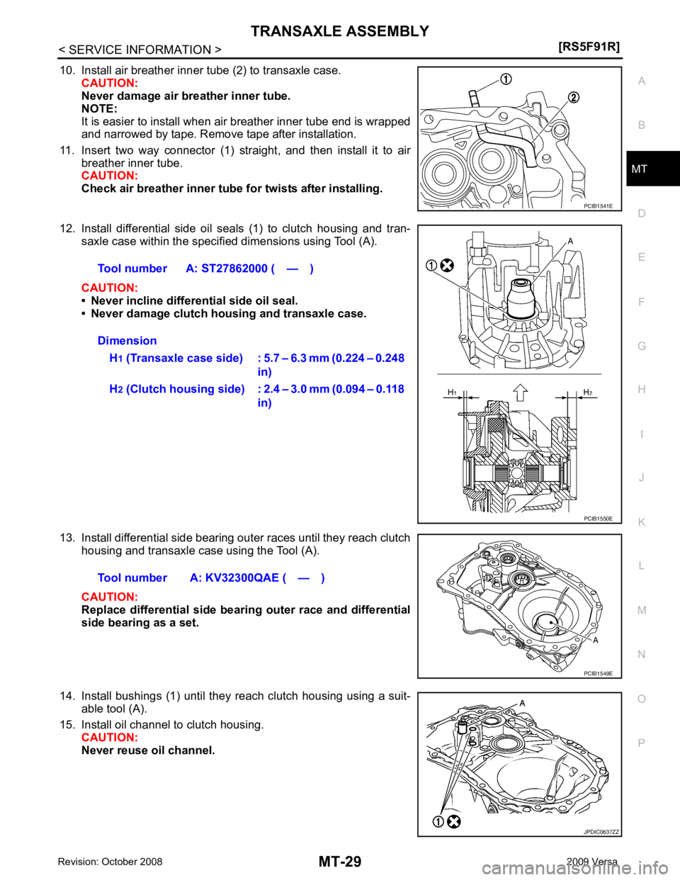
10. Install air breather inner tube (2) to transaxle case.
CAUTION:
Never damage air breather inner tube.
NOTE:
It is easier to install when air breather inner tube end is wrapped
and narrowed by tape. Remove tape after installation.
11. Insert two way connector (1) straight, and then install it to air breather inner tube.
CAUTION:
Check air breather inner tube fo r twists after installing.
12. Install differential side oil seals (1) to clutch housing and tran- saxle case within the specified dimensions using Tool (A).
CAUTION:
• Never incline differential side oil seal.
• Never damage clutch housing and transaxle case.
13. Install differential side bearing outer races until they reach clutch housing and transaxle case using the Tool (A).
CAUTION:
Replace differential side bearing outer race and differential
side bearing as a set.
14. Install bushings (1) until they reach clutch housing using a suit- able tool (A).
15. Install oil channel to clutch housing. CAUTION:
Never reuse oil channel. JPDIC0637ZZ
Page 3835 of 4331
FINAL DRIVE
MT-41
< SERVICE INFORMATION >
[RS5F91R] D
E
F
G H
I
J
K L
M A
B MT
N
O P
FINAL DRIVE
Disassembly and Assembly INFOID:0000000004788552
DISASSEMBLY 1. Remove differential side bearings using Tool (A) and a suitable tool.
2. Remove speedometer drive gear.
INSPECTION AFTER DISASSEMBLY
Case Check differential case and replace if necessary.
Bearing Check bearing for damage and unsmooth rotation. Replace if neces-
sary.
CAUTION:
Replace differential side bearing outer race and differential side
bearing as a set.
ASSEMBLY 1. Install speedometer drive gear.
2. Install differential side bearings using Tool (A).
CAUTION:
Replace differential side bearing outer race and differential
side bearing as a set. Tool number A: ST33052000 ( — ) PCIB1568E
SPD715
Tool number A: KV40104920 ( — )
PCIB1570E
Page 3839 of 4331

MT
N
O P
PREPARATION
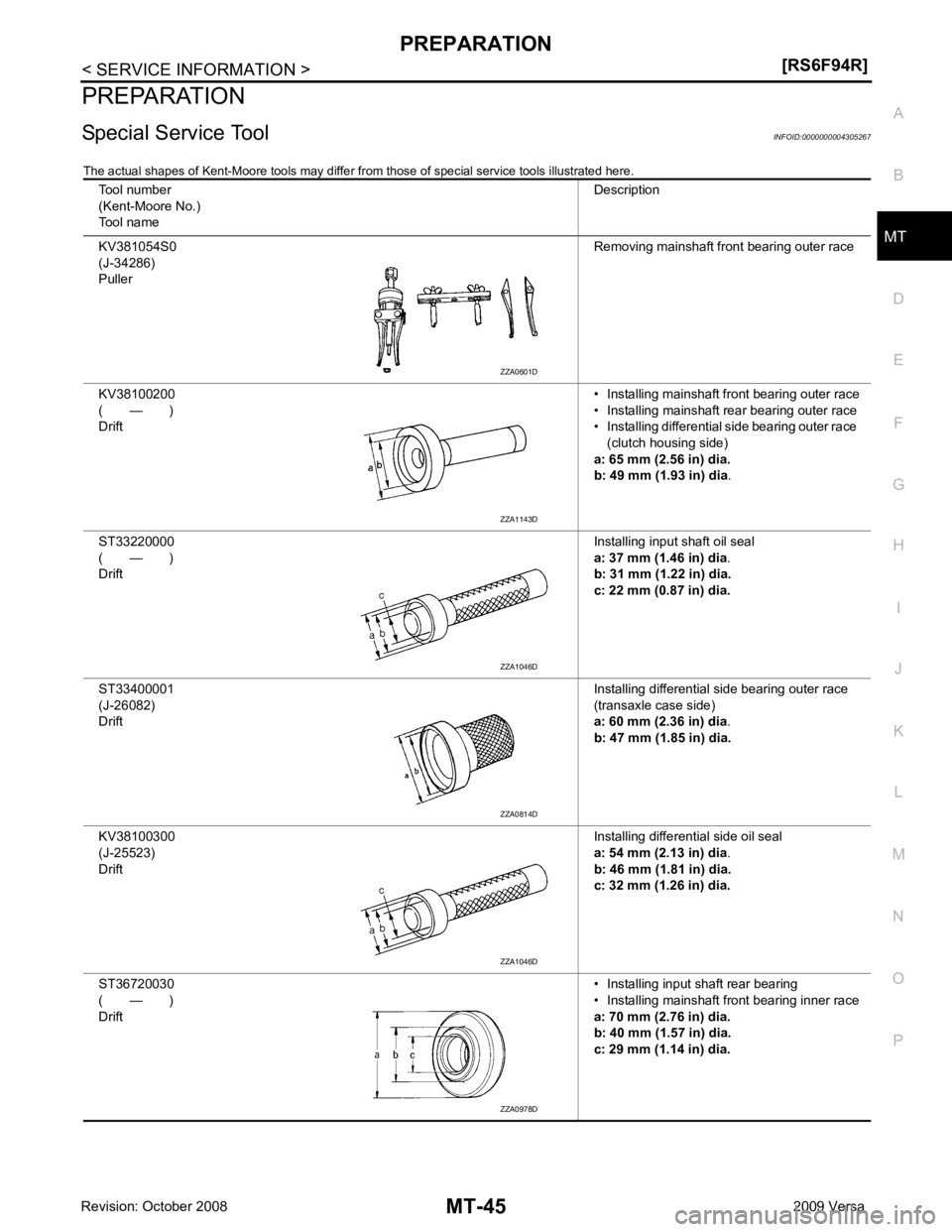
Special Service Tool INFOID:0000000004305267
The actual shapes of Kent-Moore tools may differ fr om those of special service tools illustrated here.
Tool number
(Kent-Moore No.)
Tool name Description
KV381054S0
(J-34286)
Puller Removing mainshaft front bearing outer race
KV38100200
( — )
Drift • Installing mainshaft front bearing outer race
• Installing mainshaft rear bearing outer race
• Installing differential side bearing outer race
(clutch housing side)
a: 65 mm (2.56 in) dia.
b: 49 mm (1.93 in) dia .
ST33220000
( — )
Drift Installing input shaft oil seal
a: 37 mm (1.46 in) dia .
b: 31 mm (1.22 in) dia.
c: 22 mm (0.87 in) dia.
ST33400001
(J-26082)
Drift Installing differential side bearing outer race
(transaxle case side)
a: 60 mm (2.36 in) dia .
b: 47 mm (1.85 in) dia.
KV38100300
(J-25523)
Drift Installing differential side oil seal
a: 54 mm (2.13 in) dia .
b: 46 mm (1.81 in) dia.
c: 32 mm (1.26 in) dia.
ST36720030
( — )
Drift • Installing input shaft rear bearing
• Installing mainshaft front bearing inner race
a: 70 mm (2.76 in) dia.
b: 40 mm (1.57 in) dia.
c: 29 mm (1.14 in) dia. ZZA1143D
ZZA1046D
ZZA1046D
ZZA0978D